stop start DODGE DURANGO 2013 3.G Service Manual
[x] Cancel search | Manufacturer: DODGE, Model Year: 2013, Model line: DURANGO, Model: DODGE DURANGO 2013 3.GPages: 699, PDF Size: 5.53 MB
Page 483 of 699
CAUTION!
Extreme steering maneuvers may cause the electri-
cally driven pump to reduce or stop power steering
assistance in order to prevent damage to the system.
Normal operation will resume once the system is
allowed to cool.If the “SERVICE POWER STEERING SYSTEM”
message and a flashing icon are displayed on
the EVIC screen, it indicates that the vehicle
needs to be taken to the dealer for service. It is
likely the vehicle has lost power steering assistance. Refer
to “Electronic Vehicle Information (EVIC)” in “Under-
standing Your Instrument Panel” for further information.
If the “POWER STEERING SYSTEM OVER TEMP” mes-
sage and an icon are displayed on the EVIC screen, it
indicates that extreme steering maneuvers may have occurred, which caused an over temperature condition in
the power steering system. You will lose power steering
assistance momentarily until the over temperature con-
dition no longer exists. Once driving conditions are safe,
then pull over and let vehicle idle for a few moments
until the light turns off. Refer to “Electronic Vehicle
Information (EVIC)” in “Understanding Your Instrument
Panel” for further information.
NOTE:
•
Even if power steering assistance is no longer opera-
tional, it is still possible to steer the vehicle. Under
these conditions there will be a substantial increase in
steering effort, especially at very low vehicle speeds
and during parking maneuvers.
• If the condition persists, see your authorized dealer for
service.
5
STARTING AND OPERATING 481
Page 490 of 699
Brake Assist System (BAS)
The BAS is designed to optimize the vehicle’s braking
capability during emergency braking maneuvers. The
system detects an emergency braking situation by sens-
ing the rate and amount of brake application and then
applies optimum pressure to the brakes. This can help
reduce braking distances. The BAS complements the
anti-lock brake system (ABS). Applying the brakes very
quickly results in the best BAS assistance. To receive the
benefit of the system, you must applycontinuousbrak-
ing pressure during the stopping sequence (do not
“pump” the brakes). Do not reduce brake pedal pressure
unless braking is no longer desired. Once the brake pedal
is released, the BAS is deactivated.
WARNING!
• The BAS cannot prevent the natural laws of phys-
ics from acting on the vehicle, nor can it increase
the traction afforded by prevailing road conditions.
• The BAS cannot prevent collisions, including those
resulting from excessive speed in turns, driving on
very slippery surfaces, or hydroplaning.
• The capabilities of a BAS-equipped vehicle must
never be exploited in a reckless or dangerous
manner which could jeopardize the user’s safety or
the safety of others.
488 STARTING AND OPERATING
Page 495 of 699
Off” mode is overcome, turn ESC back on by momen-
tarily pressing the “ESC OFF” switch. This may be done
while the vehicle is in motion.
WARNING!
When in “Partial Off” mode, the enhanced vehicle
stability offered by the ESC system is reduced.
AWD Low Range (LOW)
Partial Off
This is the normal operating mode for ESC in AWD LOW
range. Whenever the vehicle is started in AWD LOW
range, or the transfer case (if equipped) is shifted from
AWD AUTO range or NEUTRAL to AWD LOW range,
the ESC system will be in the “Partial Off” mode.
Trailer Sway Control (TSC)
TSC uses sensors in the vehicle to recognize an exces-
sively swaying trailer and will take the appropriate
actions to attempt to stop the sway. The system may
reduce engine power and apply the brake of the appro-
priate wheel(s) to counteract the sway of the trailer. TSC
will become active automatically once an excessively
swaying trailer is recognized. No driver action is re-
quired. Note that TSC cannot stop all trailers from
swaying. Always use caution when towing a trailer and
follow the trailer tongue weight recommendations. Refer
to “Trailer Towing” in “Starting and Operating” for
further information. When TSC is functioning, the “ESC
Activation/Malfunction Indicator Light” will flash, the
engine power may be reduced and you may feel the
brakes being applied to individual wheels to attempt to
stop the trailer from swaying. TSC is disabled when the
ESC system is in the “Partial Off” mode.
5
STARTING AND OPERATING 493
Page 496 of 699
WARNING!
If TSC activates while driving, slow the vehicle
down, stop at the nearest safe location, and adjust the
trailer load to eliminate trailer sway.
Hill Start Assist (HSA)
The HSA system is designed to assist the driver when
starting a vehicle from a stop on a hill. HSA will maintain
the level of brake pressure the driver applied for a short
period of time after the driver takes their foot off of the
brake pedal. If the driver does not apply the throttle
during this short period of time, the system will release
brake pressure and the vehicle will roll down the hill. The
system will release brake pressure in proportion to the
amount of throttle applied as the vehicle starts to move in
the intended direction of travel.
HSA Activation Criteria
The following criteria must be met in order for HSA to
activate:
•Vehicle must be stopped.
• Vehicle must be on a 6% (approximate) grade or
greater hill.
• Gear selection matches vehicle uphill direction (i.e.,
vehicle facing uphill is in forward gear; vehicle back-
ing uphill is in REVERSE gear).
HSA will work in REVERSE and all forward gears when
the activation criteria have been met. The system will not
activate if the vehicle is placed in NEUTRAL or PARK.
494 STARTING AND OPERATING
Page 500 of 699
NOTE:
•The “ESC Activation/Malfunction Indicator Light”
and the “ESC OFF Indicator Light” come on momen-
tarily each time the ignition switch is turned ON.
• Each time the ignition is turned ON, the ESC system
will be ON even if it was turned off previously.
• The ESC system will make buzzing or clicking sounds
when it is active. This is normal; the sounds will stop
when ESC becomes inactive following the maneuver
that caused the ESC activation.
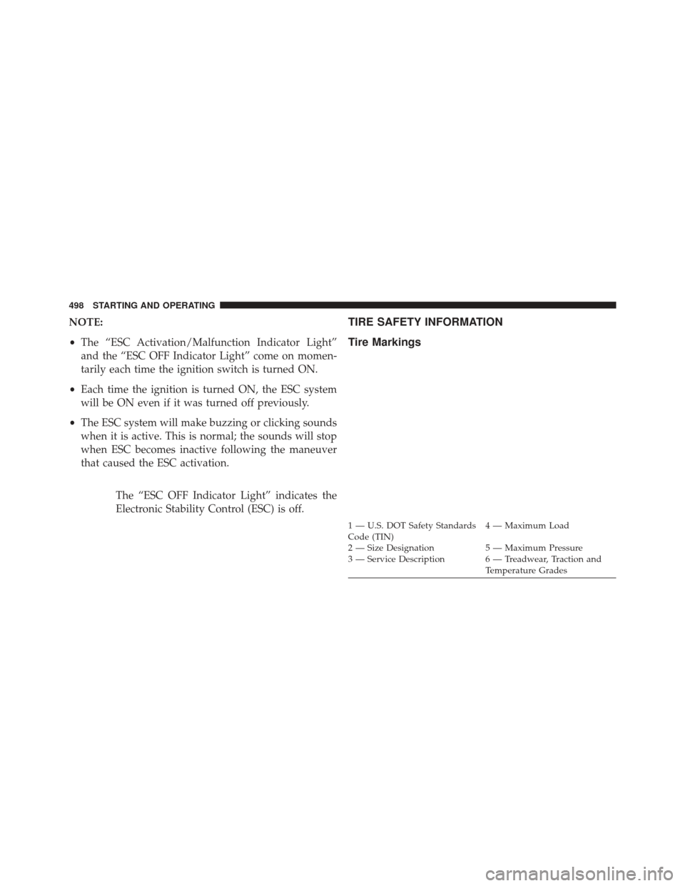
The “ESC OFF Indicator Light” indicates the
Electronic Stability Control (ESC) is off.TIRE SAFETY INFORMATION
Tire Markings
1 — U.S. DOT Safety Standards
Code (TIN) 4 — Maximum Load
2 — Size Designation 5 — Maximum Pressure
3 — Service Description 6 — Treadwear, Traction and Temperature Grades
498 STARTING AND OPERATING
Page 511 of 699
WARNING!
Overloading of your tires is dangerous. Overloading
can cause tire failure, affect vehicle handling, and
increase your stopping distance. Use tires of the
recommended load capacity for your vehicle. Never
overload them.
TIRES — GENERAL INFORMATION
Tire Pressure
Proper tire inflation pressure is essential to the safe and
satisfactory operation of your vehicle. Three primary
areas are affected by improper tire pressure:
Safety
WARNING!
•Improperly inflated tires are dangerous and can
cause collisions.
• Under-inflation increases tire flexing and can re-
sult in over-heating and tire failure.
• Over-inflation reduces a tire’s ability to cushion
shock. Objects on the road and chuckholes can
cause damage that result in tire failure.
• Over-inflated or under-inflated tires can affect ve-
hicle handling and can fail suddenly, resulting in
loss of vehicle control.
• Unequal tire pressures can cause steering prob-
lems. You could lose control of your vehicle.
(Continued)
5
STARTING AND OPERATING 509
Page 518 of 699
your original equipment tire, replace (or repair) the
original equipment tire and reinstall on the vehicle at the
first opportunity.
WARNING!
Limited-use spares are for emergency use only. In-
stallation of this limited-use spare tire affects vehicle
handling. With this tire, do not drive more than the
speed listed on the limit-use spare wheel. Keep
inflated to the cold tire inflation pressure listed on
your Tire and Loading Information Placard located
on the driver ’s side door opening. Replace (or repair)
the original equipment tire at the first opportunity
and reinstall it on your vehicle. Failure to do so could
result in loss of vehicle control.
Tire Spinning
When stuck in mud, sand, snow, or ice conditions, do not
spin your vehicle’s wheels above 30 mph (48 km/h) or
for longer than 30 seconds continuously without stop-
ping when you are stuck.
Refer to “Freeing A Stuck Vehicle” in “What To Do In
Emergencies” for further information.
WARNING!
Fast spinning tires can be dangerous. Forces gener-
ated by excessive wheel speeds may cause tire dam-
age or failure. A tire could explode and injure some-
one. Do not spin your vehicle’s wheels faster than
30 mph (48 km/h) for more than 30 seconds continu-
ously when you are stuck, and do not let anyone near
a spinning wheel, no matter what the speed.
516 STARTING AND OPERATING
Page 522 of 699
TIRE CHAINS (TRACTION DEVICES)
Use of traction devices require sufficient tire-to-body
clearance. Follow these recommendations to guard
against damage.
•Traction device must be of proper size for the tire, as
recommended by the traction device manufacturer.
• Install on Rear Tires Only
• Due to limited clearance, the Security Chain Company
(SCC) Super Z6 low profile traction device or equiva-
lent is recommended on P265/60R18 or 265/50R20
tires.
WARNING!
Using tires of different size and type (M+S, Snow)
between front and rear axles can cause unpredictable
handling. You could lose control and have a collision.
CAUTION!
To avoid damage to your vehicle or tires, observe the
following precautions:
• Because of restricted traction device clearance be-
tween tires and other suspension components, it is
important that only traction devices in good condi-
tion are used. Broken devices can cause serious
damage. Stop the vehicle immediately if noise
occurs that could indicate device breakage. Remove
the damaged parts of the device before further use.
• Install device as tightly as possible and then re-
tighten after driving about ½ mile (0.8 km).
• Do not exceed 30 mph (48 km/h).
• Drive cautiously and avoid severe turns and large
bumps, especially with a loaded vehicle.
• Do not drive for prolonged period on dry pave-
ment.
(Continued)
520 STARTING AND OPERATING
Page 526 of 699
CAUTION!
•The TPMS has been optimized for the original
equipment tires and wheels. TPMS pressures have
been established for the tire size equipped on your
vehicle. Undesirable system operation or sensor
damage may result when using replacement equip-
ment that is not of the same size, type, and/or style.
Aftermarket wheels can cause sensor damage. Do
not use aftermarket tire sealants or balance beads if
your vehicle is equipped with a TPMS, as damage
to the sensors may result.
• After inspecting or adjusting the tire pressure al-
ways reinstall the valve stem cap. This will prevent
moisture and dirt from entering the valve stem,
which could damage the Tire Pressure Monitoring
Sensor. NOTE:
•
The TPMS is not intended to replace normal tire care
and maintenance, or to provide warning of a tire
failure or condition.
• The TPMS should not be used as a tire pressure gauge
while adjusting your tire pressure.
• Driving on a significantly under-inflated tire causes
the tire to overheat and can lead to tire failure.
Under-inflation also reduces fuel efficiency and tire
tread life, and may affect the vehicle’s handling and
stopping ability.
• The TPMS is not a substitute for proper tire mainte-
nance, and it is the driver ’s responsibility to maintain
correct tire pressure using an accurate tire gauge, even
if under-inflation has not reached the level to trigger
illumination of the Tire Pressure Monitoring Telltale
Light.
524 STARTING AND OPERATING
Page 527 of 699
•Seasonal temperature changes will affect tire pressure,
and the TPMS will monitor the actual tire pressure in
the tire.
Base System
The Tire Pressure Monitor System (TPMS) uses wireless
technology with wheel rim-mounted electronic sensors to
monitor tire pressure levels. Sensors, mounted to each
wheel as part of the valve stem, transmit tire pressure
readings to the Receiver Module.
NOTE: It is particularly important, for you to regularly
check the tire pressure in all of your tires, and to maintain
the proper pressure.
The TPMS consists of the following components:
• Receiver Module
• Four Tire Pressure Monitoring Sensors
• Tire Pressure Monitoring Telltale Light A tire pressure monitoring sensor is located in the spare
wheel, if the vehicle is equipped with a matching full-size
spare wheel and tire assembly. The matching full-size
spare tire can be used in place of any of the four road
tires. A low spare tire will not cause the “Tire Pressure
Monitoring Telltale Light” to illuminate, a warning mes-
sage to appear, or the chime to sound.
The “Tire Pressure Monitoring Telltale Light” will
illuminate in the instrument cluster, a “LOW TIRE
PRESSURE” message will display in the instrument
cluster for a minimum of five seconds, and an audible
chime will be activated, when one or more of the four
active road tire pressures are low. Should this occur, you
should stop as soon as possible, check the inflation
pressure of each tire on your vehicle, and inflate each tire
to the vehicle’s recommended cold placard pressure
value. The system will automatically update and the
“Tire Pressure Monitoring Telltale Light” will extinguish,
once the updated tire pressures have been received. The
5
STARTING AND OPERATING 525