audio DODGE DURANGO 2013 3.G Owner's Manual
[x] Cancel search | Manufacturer: DODGE, Model Year: 2013, Model line: DURANGO, Model: DODGE DURANGO 2013 3.GPages: 140, PDF Size: 4.38 MB
Page 72 of 140
• You will see a favorite star indicator in the upper right side of the screen below the “SAT”soft-key and a pop up will alert you that a favorite song or artist is currently playing on one
of the SiriusXM satellite radio channels.
NOTE:
Refer to your Uconnect® 730N or 430/430N
User's Manual for more information.
Display SAT Favorites List
• Touch the “Search/Browse” soft-key and select “Favorites” from the SAT Browse screen.
• Touch the desired favorites soft-key to switch the SAT tuner to the corresponding
channel.
• You may use the “LIST” soft-key to toggle between:• Favorite Songs
• Favorite Artists
• Currently playing favorites
Replay
• While you are in SAT mode, you can replay 44 minutes of the current SiriusXM channel (when the channel is changed, this audio buffer is erased). Press the REPLAY button to
listen to the stored audio.
• You can touch the on-screen controls to pause and rewind audio playback, touch
the SCAN button to preview each of the
tracks stored in the buffer, or select a
track from the list.
• The time displayed below the bar indi- cates how much time is present between
the current buffer play position and the
live broadcast.
ELECTRONICS
70
Page 74 of 140
STEERING WHEEL AUDIO CONTROLS
•The steering wheel audio controls are lo-
cated on the rear surface of the steering
wheel.
Right Switch
• Press the switch up or down to increase or decrease the volume.
• Press the button in the center to change modes AM/FM/CD/SAT.
Left Switch
• Press the switch up or down to search for the next listenable station or select the
next or previous CD track.
• Press the button in the center to select the next preset station (radio) or to change CDs if equipped with a CD Changer.
iPod®/USB/MP3 CONTROL
• There are many ways to play music from iPod®/MP3 players or USB devices through yourvehicle's sound system.
• The remote USB port, located within the center console, allows you to plug an iPod® into the vehicle's sound system.
NOTE:
If equipped with the Uconnect® 730N, the
USB port on the faceplate allows the same
functions as the remote USB port.
•
Non-Touch-Screen Radios:To hear audio
from devices connected to the USB port,
press the “AUX” button on the radio face-
plate.
ELECTRONICS
72
Page 75 of 140
•Touch-Screen Radios:To hear audio from devices connected to the USB port, press the
“MEDIA” hard-key, then touch the “AUX” or “iPod®” soft-key.
• When connected to this feature: • The iPod® can be controlled using the
radio buttons to Play, Browse, and List
the iPod® or external devices contents.
•
The iPod® battery charges when plugged
into the USB port (if supported by the spe-
cific audio device).
• Compatible iPod® devices may also be
controllable using voice commands.
Refer to the Owner's Manual on the DVD for details.
NOTE:
The USB port supports certain Mini, Classic, Nano, Touch, and iPhone® devices. The USB
port also supports playing music from compatible external USB Mass Storage Class
memory devices. For supported audio file formats, refer to the USB Port section in the
Owner's Manual on the DVD. Refer to www.UconnectPhone.com website for a list of tested
iPod®s. Some iPod® software versions may not fully support the USB port features. Please
visit Apple’s website for iPod® software updates.
Second Row USB Charging Port
• The second row USB connector port can be used for charging purposes only. Use the connection cable to connect an iPod® or external USB device to the vehicle's USB
charging port which is located in the second row center console.
NOTE:
If the device battery to be charged is com-
pletely depleted, it may take awhile to charge.
WARNING!
Do not plug in or remove the iPod® or external device while driving. Failure to follow this
warning could result in a collision.
ELECTRONICS
73
Page 78 of 140
Mute (Or Unmute) Microphone During Call
• During a call, press the “Voice Command” button
.
• After the BEEP, say “mute” (or “mute off”).
Transfer Ongoing Call Between Handset And Vehicle
• During a call, press the “Voice Command” button
.
• After the BEEP, say “transfer call”.
Changing The Volume
• Start a dialogue by pressing the “Phone” button
, then adjust the volume during a
normal call.
• Use the radio ON/OFF VOLUME rotary knob to adjust the volume to a comfortable level while the Uconnect® system is speaking. Please note the volume setting for Uconnect®
is different than the audio system.
WARNING!
• Any voice commanded system should be used only in safe driving conditions follow-
ing applicable laws regarding phone use. Your attention should be focused on safely
operating the vehicle. Failure to do so may result in a collision causing you and others
to be severely injured or killed.
• In an emergency, to use Uconnect® Phone, your mobile phone must be:
• turned on,
• paired to Uconnect® Phone,
• and have network coverage.
Uconnect® VOICE COMMAND
Voice Command Operation
• The Uconnect® Voice Command system allows you to control your AM, FM radio, satelliteradio, disc player, HDD, Uconnect® Phone, a memo recorder, and supported portable
media devices.
• When you press the “Voice Command” button
located on the radio faceplate or
steering wheel, you will hear a beep. The beep is your signal to give a command. If you do
not say a command within a few seconds, the system will present you with a list of
options. If you ever wish to interrupt the system while it lists options, press the “Voice
Command” button
, listen for the BEEP, and say your command.
NOTE:
Visit http://www.driveuconnect.com/features/voiceCommand/ for more info on which
voice command features apply to your vehicle.
ELECTRONICS
76
Page 81 of 140
Bluetooth® STREAMING AUDIO
•If equipped with Uconnect® Voice Com-
mand, your Bluetooth-equipped iPod® de-
vices, cell phones or other media players,
may also be able to stream music to your
vehicles speakers. Your connected device
must be Bluetooth-compatible, and paired
with your radio (see Uconnect® Phone for
pairing instructions).
•Non-Touch-Screen Radios:Press the “AUX”
button on the radio faceplate until "BT" or
“Audio Streaming” is displayed on the radio screen.
• Touch-Screen-Radios: Press the “RADIO/MEDIA” or “MEDIA” hard-key and then touch
the “AUX” soft-key tab.
VIDEO ENTERTAINMENT SYSTEM (VES™)
System Operation
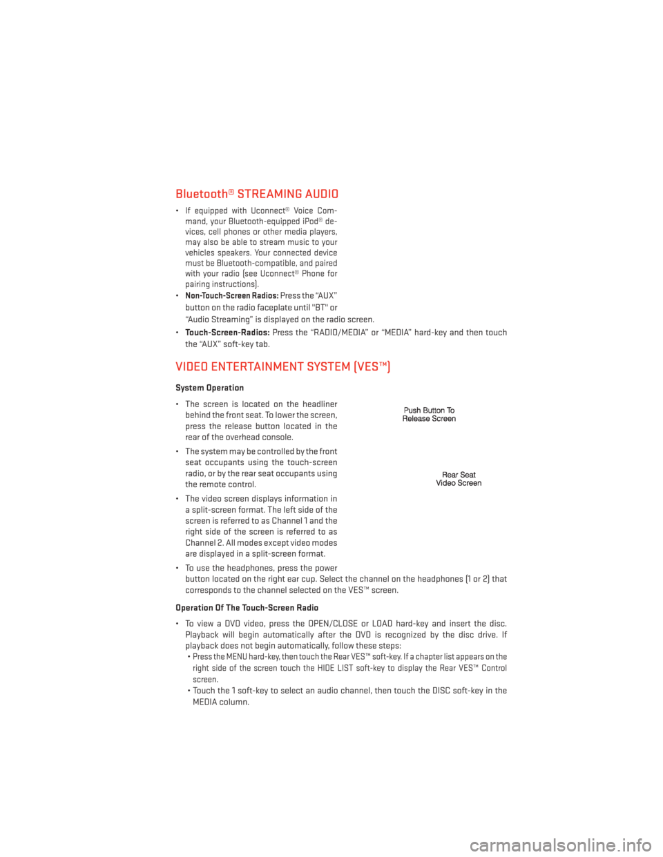
• The screen is located on the headliner behind the front seat. To lower the screen,
press the release button located in the
rear of the overhead console.
• The system may be controlled by the front seat occupants using the touch-screen
radio, or by the rear seat occupants using
the remote control.
• The video screen displays information in a split-screen format. The left side of the
screen is referred to as Channel 1 and the
right side of the screen is referred to as
Channel 2. All modes except video modes
are displayed in a split-screen format.
• To use the headphones, press the power button located on the right ear cup. Select the channel on the headphones (1 or 2) that
corresponds to the channel selected on the VES™ screen.
Operation Of The Touch-Screen Radio
• To view a DVD video, press the OPEN/CLOSE or LOAD hard-key and insert the disc. Playback will begin automatically after the DVD is recognized by the disc drive. If
playback does not begin automatically, follow these steps:•
Press the MENU hard-key, then touch the Rear VES™ soft-key. If a chapter list appears on the
right side of the screen touch the HIDE LIST soft-key to display the Rear VES™ Control
screen.
• Touch the 1 soft-key to select an audio channel, then touch the DISC soft-key in the
MEDIA column.
ELECTRONICS
79
Page 82 of 140
Operation Of The Remote
•
The remote control operates similarly to any DVD remote you have used before and allows
the rear seat passengers to change stations, tracks, discs and audio/video modes.
• The remote control is designed to control either channel by using the selector switch located on the right side of the remote.
• Pressing the power button will turn the VES™ system ON/OFF.
• Pressing the MODE button causes the Mode Selection menu to appear on the VES™ screen. Use the remote control arrow buttons to scroll through the available modes, then
press ENTER to select the desired mode.
Auxiliary Audio/Video Input Jacks
• The Aux jacks are located on the rear of the center console.
• Connect the video game or other external media devices to the AUX jacks following the color coding for VES™ jacks.
• Using either the touch-screen radio or remote control, select AUX from the Rear VES™ Control or Mode Selection screen.
• Refer to your vehicle's Owners Manual on the DVD for further details.
ELECTRONIC VEHICLE INFORMATION CENTER (EVIC)
• The EVIC features a driver interactive display that is located in the instrument cluster. Pressing the controls on the left side of the steering wheel allows the driver to select
vehicle information and Personal Settings. For additional information, refer to Program-
mable Features in this guide.
• Press and release the UP
button to
scroll upward through the main menus
(Fuel Economy, Vehicle Speed Trip Info,
Tire PSI, Vehicle Info, Messages, Units,
System Setup) and sub menus.
• Press and release the DOWN
button
to scroll downward through the main
menus and sub menus.
•
Press and release the SELECTbutton
for access to main menus, sub menus or to
select a personal setting in the setup menu.
• Press the BACK button to scroll back to a previous menu or sub menu.
NOTE:
Refer to the Driver Cockpit image in Controls At A Glance to see EVIC Display and EVIC
Controls location.
ELECTRONICS
80
Page 128 of 140
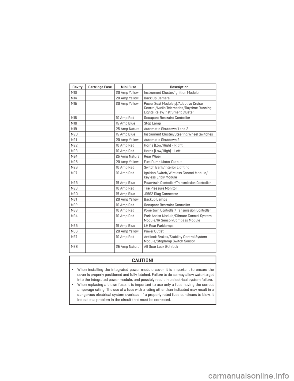
Cavity Cartridge Fuse Mini FuseDescription
M13 20 Amp Yellow Instrument Cluster/Ignition Module
M14 20 Amp Yellow Back Up Camera
M15 20 Amp Yellow Power Seat Module(s)/Adaptive Cruise
Control/Audio Telematics/Daytime Running
Lights Relay/Instrument Cluster
M16 10 Amp Red Occupant Restraint Controller
M18 15 Amp Blue Stop Lamp
M19 25 Amp Natural Automatic Shutdown 1 and 2
M20 15 Amp Blue Instrument Cluster/Steering Wheel Switches
M21 20 Amp Yellow Automatic Shutdown 3
M22 10 Amp Red Horns (Low/High) – Right
M23 10 Amp Red Horns (Low/High) – Left
M24 25 Amp Natural Rear Wiper
M25 20 Amp Yellow Fuel Pump Motor Output
M26 10 Amp Red Switch Bank/Interior Lighting
M27 10 Amp Red Ignition Switch/Wireless Control Module/
Keyless Entry Module
M28 15 Amp Blue
Powertrain Controller/Transmission Controller
M2910 Amp Red Tire Pressure Monitor
M30 15 Amp Blue J1962 Diag Connector
M31 20 Amp Yellow Backup Lamps
M32 10 Amp Red Occupant Restraint Controller
M33 10 Amp Red
Powertrain Controller/Transmission Controller
M3410 Amp Red Park Assist Module/Climate Control System
Module/IR Sensor/Compass Module
M35 15 Amp Blue LH Rear Parklamps
M36 20 Amp Yellow Power Outlet
M37 10 Amp Red Antilock Brakes/Stability Control System
Module/Stoplamp Switch Sensor
M38 25 Amp Natural All Door Lock &Unlock
CAUTION!
• When installing the integrated power module cover, it is important to ensure the
cover is properly positioned and fully latched. Failure to do so may allow water to get
into the integrated power module, and possibly result in a electrical system failure.
• When replacing a blown fuse, it is important to use only a fuse having the correct
amperage rating. The use of a fuse with a rating other than indicated may result in a
dangerous electrical system overload. If a properly rated fuse continues to blow, it
indicates a problem in the circuit that must be corrected.
MAINTAINING YOUR VEHICLE
126
Page 135 of 140
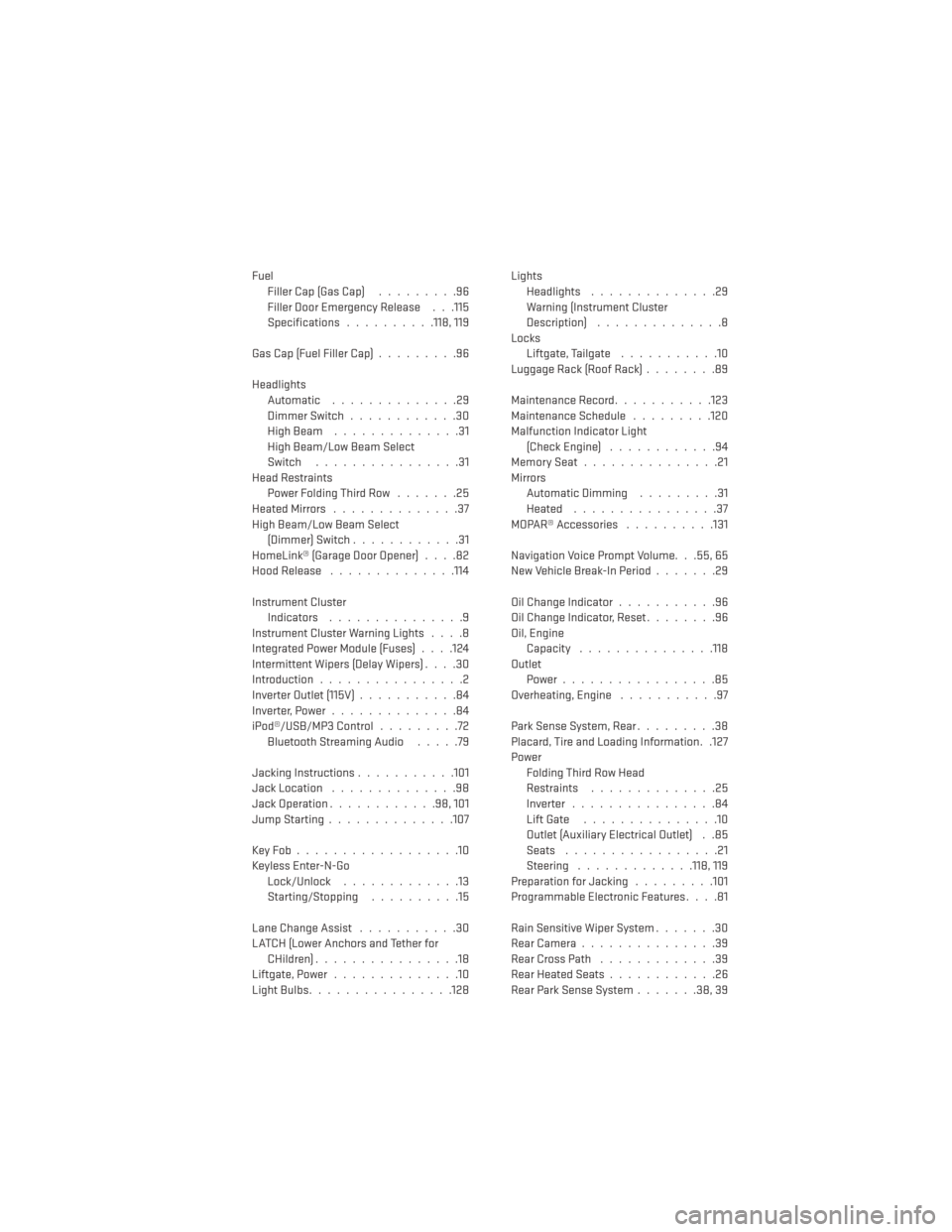
FuelFiller Cap (Gas Cap) .........96
Filler Door Emergency Release . . .115
Specifications ..........118, 119
Gas Cap (Fuel Filler Cap) .........96
Headlights Automatic ..............29
Dimmer Switch ............30
HighBeam ..............31
High Beam/Low Beam Select
Switch ................31
Head Restraints Power Folding Third Row .......25
HeatedMirrors ..............37
High Beam/Low Beam Select (Dimmer) Switch ............31
HomeLink® (Garage Door Opener) ....82
Hood Release ..............114
Instrument Cluster Indicators ...............9
Instrument Cluster Warning Lights ....8
Integrated Power Module (Fuses) . . . .124
Intermittent Wipers (Delay Wipers) ....30
Introduction ................2
Inverter Outlet (115V) ...........84
Inverter,Power..............84
iPod®/USB/MP3 Control .........72
BluetoothStreamingAudio .....79
Jacking Instructions ...........101
Jack Location ..............98
Jack Operation ............98,101
JumpStarting..............107
KeyFob..................10
Keyless Enter-N-Go Lock/Unlock .............13
Starting/Stopping ..........15
Lane Change Assist ...........30
LATCH (Lower Anchors and Tether for CHildren)................18
Liftgate, Power ..............10
LightBulbs................128 Lights
Headlights ..............29
Warning (Instrument Cluster
Description) ..............8
Locks Liftgate, Tailgate ...........10
Luggage Rack (Roof Rack) ........89
Maintenance Record ...........123
Maintenance Schedule .........120
Malfunction Indicator Light (Check Engine) ............94
MemorySeat...............21
Mirrors Automatic Dimming .........31
Heated ................37
MOPAR® Accessories ..........131
Navigation Voice Prompt Volume. . .55, 65
New Vehicle Break-In Period .......29
Oil Change Indicator ...........96
Oil Change Indicator, Reset ........96
Oil, Engine Capacity .............. .118
Outlet Power.................85
Overheating, Engine ...........97
Park Sense System, Rear .........38
Placard, Tire and Loading Information. .127
Power Folding Third Row Head
Restraints ..............
25
Inverter ................84
Lift Gate ...............10
Outlet (Auxiliary Electrical Outlet) . .85
Seats .................21
Steering .............118, 119
Preparation for Jacking .........101
Programmable Electronic Features ....81
Rain Sensitive Wiper System .......30
RearCamera...............39
RearCrossPath .............39
Rear Heated Seats ............26
Rear Park Sense System .......38,39
INDEX
133
Page 137 of 140
FREQUENTLY ASKED QUESTIONS
GETTING STARTED
• How do I install my LATCH Equipped Child Seat? pg. 18
• How do I program my Front Seat Memory? pg. 21
OPERATING YOUR VEHICLE
• How does the Electronic Range Select (ERS) operate? pg. 36
ELECTRONICS
• Which radio is in my vehicle?• Uconnect® 130 pg. 44
• Uconnect® 130 WITH SiriusXM™ pg. 46
• Uconnect® 430/430N pg. 48
• Uconnect® 730N pg. 58
• How do I activate the Audio Jack?
• Uconnect® 130 pg. 48
• Uconnect® 130 WITH SiriusXM™ pg. 48
• Uconnect® 430/430N pg. 52
• Uconnect® 730N pg. 62
• How do I set the clock on my radio?
• Uconnect® 130 pg. 46
• Uconnect® 130 WITH SiriusXM™ pg. 46
• Uconnect® 430/430N pg. 49
• Uconnect® 730N pg. 58
• How do I use the Navigation feature?
• Uconnect® 430/430N pg. 54
• Uconnect® 730N pg. 65
• How do I pair my cell phone via Bluetooth® with the Uconnect® Hands-Free Voice Activation System? pg. 49
• How do I use my USB port to listen to audio through my touch-screen radio? pg. 72
• What does the ECO message mean on the EVIC display? pg. 81
FAQ (How To?)
135