engine DODGE DURANGO 2013 3.G Owner's Manual
[x] Cancel search | Manufacturer: DODGE, Model Year: 2013, Model line: DURANGO, Model: DODGE DURANGO 2013 3.GPages: 140, PDF Size: 4.38 MB
Page 110 of 140
Jump-Starting Procedure
• Connect the positive(+)end of the jumper cable to the remote positive (+)post of the
discharged vehicle.
• Connect the opposite end of the positive (+)jumper cable to the positive (+)post of the
booster battery.
• Remove the protective cap from the negative jump post. Connect the negative end (-)of
the jumper cable to the negative (-)post of the booster battery.
• Connect the opposite end of the negative (-)jumper cable to the remote negative (-)post
of the vehicle with the discharged battery.
• Start the engine in the vehicle that has the booster battery, let the engine idle a few minutes, and then start the engine in the vehicle with the discharged battery.
• Once the engine is started, remove the jumper cables in the reverse sequence:
• Disconnect the negative (-)jumper cable from the remote negative (-)post of the vehicle
with the discharged battery. Replace the protective cap.
• Disconnect the negative end (-)of the jumper cable from the negative (-)post of the
booster battery.
• Disconnect the opposite end of the positive (+)jumper cable from the positive (+)post of
the booster battery.
• Disconnect the positive (+)end of the jumper cable from the remote positive (+)post of
the discharged vehicle.
• Reinstall the protective cover over the remote positive (+)battery post of the discharged
vehicle.
• If frequent jump-starting is required to start your vehicle you should have the battery and charging system inspected at your authorized dealer.
CAUTION!
• Do not use a portable battery booster pack or any other booster source with a system voltage greater than 12 Volts or damage to the battery, starter motor, alternator or
electrical system may occur.
• Failure to follow these procedures could result in damage to the charging system of the booster vehicle or the discharged vehicle.
• Accessories that can be plugged into the vehicle power outlets draw power from the vehicle’s battery, even when not in use (i.e., cellular phones, etc.). Eventually, if
plugged in long enough, the vehicle’s battery will discharge sufficiently to degrade
battery life and/or prevent the engine from starting.
WHAT TO DO IN EMERGENCIES
108
Page 112 of 140
SHIFT LEVER OVERRIDE
•If a malfunction occurs and the shift lever
cannot be moved out of the PARK position,
you can use the following procedure to
temporarily move the shift lever:
• To access the shift lever override, re-
move the rubber cupholder liner to the
right of the shift lever.
• Firmly set the parking brake.
• Turn the ignition switch to the ACC or ON position without starting the engine.
• Press and maintain firm pressure on the brake pedal.
• Using a screwdriver or similar tool, press and hold the override tab through
the access port on the center console.
• Move the shift lever into the NEUTRAL position.
• The vehicle may then be started in NEUTRAL.
• Reinstall the override cover.
WHAT TO DO IN EMERGENCIES
110
Page 114 of 140
FREEING A STUCK VEHICLE
• If your vehicle becomes stuck in mud, sand or snow, it can often be moved by a rockingmotion. Turn your steering wheel right and left to clear the area around the front wheels.
Then, move the shift lever back and forth between REVERSE and DRIVE. Using minimal
accelerator pedal pressure to maintain the rocking motion, without spinning the wheels,
is most effective.
• Allow the engine to idle with the transmission shift lever in NEUTRAL for at least one minute after every five rocking-motion cycles. This will minimize overheating and reduce
the risk of transmission failure during prolonged efforts to free a stuck vehicle.
NOTE:
If your vehicle is equipped with Electronic Stability Control (ESC) then press the "ESC Off"
switch, to place the Electronic Stability Control (ESC) system in "Partial Off" mode, before
rocking the vehicle.
CAUTION!
Revving the engine or spinning the wheels too fast may lead to transmission overheating
and failure. It can also damage the tires. Do not spin the wheels above 30 mph (48 km/h)
while in gear (no transmission shifting occurring).
WARNING!
Fast spinning tires can be dangerous. Forces generated by excessive wheel speeds may
cause tire damage or failure. A tire could explode and injure someone. Do not spin your
vehicle's wheels faster than 30 mph (48 km/h) when you are stuck. Do not let anyone
near a spinning wheel, no matter what the speed.
WHAT TO DO IN EMERGENCIES
112
Page 118 of 140

ENGINE COMPARTMENT3.6L ENGINE
MAINTAINING YOUR VEHICLE
116
Page 119 of 140
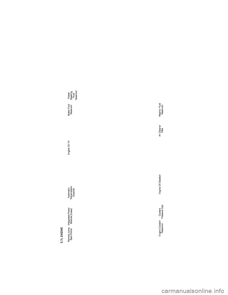
5.7L ENGINE
MAINTAINING YOUR VEHICLE
117
Page 120 of 140
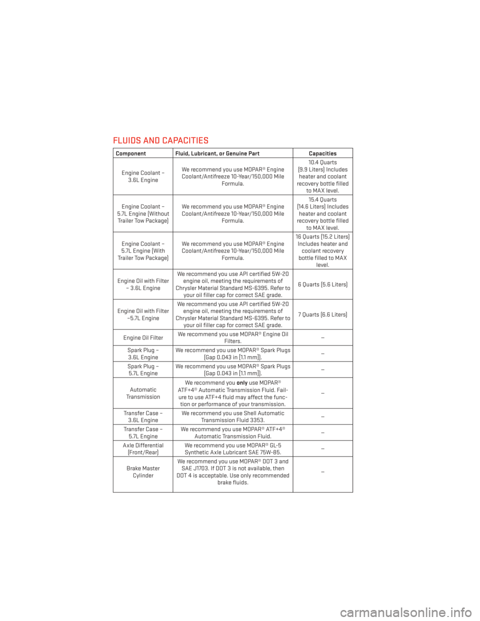
FLUIDS AND CAPACITIES
Component Fluid, Lubricant, or Genuine PartCapacities
Engine Coolant – 3.6L Engine We recommend you use MOPAR® Engine
Coolant/Antifreeze 10-Year/150,000 Mile Formula. 10.4 Quarts
(9.9 Liters) Includes heater and coolant
recovery bottle filled to MAX level.
Engine Coolant –
5.7L Engine (Without Trailer Tow Package) We recommend you use MOPAR® Engine
Coolant/Antifreeze 10-Year/150,000 Mile Formula. 15.4 Quarts
(14.6 Liters) Includes heater and coolant
recovery bottle filled to MAX level.
Engine Coolant –
5.7L Engine (With
Trailer Tow Package) We recommend you use MOPAR® Engine
Coolant/Antifreeze 10-Year/150,000 Mile Formula. 16 Quarts (15.2 Liters)
Includes heater and coolant recovery
bottle filled to MAX level.
Engine Oil with Filter – 3.6L Engine We recommend you use API certified 5W-20
engine oil, meeting the requirements of
Chrysler Material Standard MS-6395. Refer to your oil filler cap for correct SAE grade. 6 Quarts (5.6 Liters)
Engine Oil with Filter –5.7L Engine We recommend you use API certified 5W-20
engine oil, meeting the requirements of
Chrysler Material Standard MS-6395. Refer to your oil filler cap for correct SAE grade. 7 Quarts (6.6 Liters)
Engine Oil Filter We recommend you use MOPAR® Engine Oil
Filters. —
Spark Plug – 3.6L Engine We recommend you use MOPAR® Spark Plugs
(Gap 0.043 in [1.1 mm]). —
Spark Plug – 5.7L Engine We recommend you use MOPAR® Spark Plugs
(Gap 0.043 in [1.1 mm]). —
Automatic
Transmission We recommend you
onlyuse MOPAR®
ATF+4® Automatic Transmission Fluid. Fail- ure to use ATF+4 fluid may affect the func- tion or performance of your transmission. —
Transfer Case – 3.6L Engine We recommend you use Shell Automatic
Transmission Fluid 3353. —
Transfer Case – 5.7L Engine We recommend you use MOPAR® ATF+4®
Automatic Transmission Fluid. —
Axle Differential (Front/Rear) We recommend you use MOPAR® GL-5
Synthetic Axle Lubricant SAE 75W-85. —
Brake Master Cylinder We recommend you use MOPAR® DOT 3 and
SAE J1703. If DOT 3 is not available, then
DOT 4 is acceptable. Use only recommended brake fluids. —
MAINTAINING YOUR VEHICLE
118
Page 121 of 140

Component Fluid, Lubricant, or Genuine PartCapacities
Power Steering Reservoir –
3.6L Engine We recommend you use MOPAR® Hydraulic
Fluid meeting Chrysler Material Standard MS-11655. —
Power Steering Reservoir –
5.7L Engine We recommend you use MOPAR® Power
Steering Fluid +4, or MOPAR® ATF+4®
Automatic Transmission Fluid meeting Chrysler Material Standard MS-9602. —
Fuel Selection –
3.6L, 5.7L Engine 87 Octane acceptable. 89 Octane
recommended for 5.7L. 25 Gallons (94 Liters)
(Approximate)
CAUTION!
• Mixing of engine coolant (antifreeze) other than specified Organic Additive Technol-
ogy (OAT) engine coolant (antifreeze), may result in engine damage and may de-
crease corrosion protection. Organic Additive Technology (OAT) engine coolant is
different and should not be mixed with Hybrid Organic Additive Technology (HOAT)
engine coolant (antifreeze) or any “globally compatible” coolant (antifreeze). If a
non-OAT engine coolant (antifreeze) is introduced into the cooling system in an
emergency, it should be flushed with OAT coolant and replaced with the specified
OAT engine coolant (antifreeze) as soon as possible.
• Do not use water alone or alcohol-based engine coolant (antifreeze) products. Do not
use additional rust inhibitors or antirust products, as they may not be compatible
with the radiator engine coolant and may plug the radiator.
• This vehicle has not been designed for use with propylene glycol-based engine
coolant (antifreeze). Use of propylene glycol-based engine coolant (antifreeze) is not
recommended.
E-85 Flexible Fuel – 3.6L Engine Only
CAUTION!
Only vehicles with the E-85 fuel filler door label or a yellow gas cap can operate on E-85.
• Refer to your Owner's Manual on the DVD for further details.
MAINTAINING YOUR VEHICLE
119
Page 122 of 140
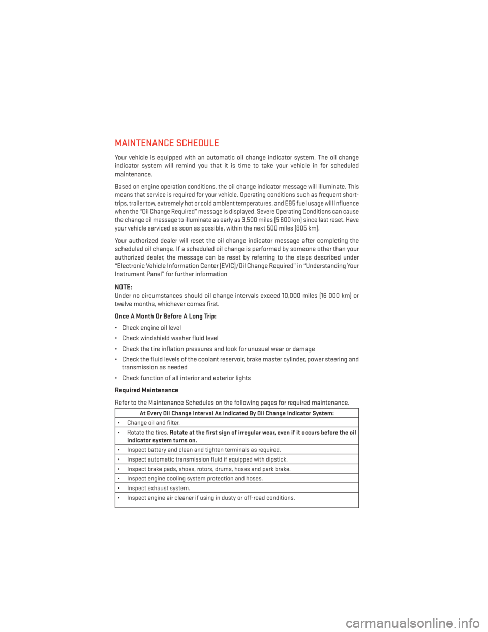
MAINTENANCE SCHEDULE
Your vehicle is equipped with an automatic oil change indicator system. The oil change
indicator system will remind you that it is time to take your vehicle in for scheduled
maintenance.
Based on engine operation conditions, the oil change indicator message will illuminate. This
means that service is required for your vehicle. Operating conditions such as frequent short-
trips, trailer tow, extremely hot or cold ambient temperatures, and E85 fuel usage will influence
when the “Oil Change Required” message is displayed. Severe Operating Conditions can cause
the change oil message to illuminate as early as 3,500 miles (5 600 km) since last reset. Have
your vehicle serviced as soon as possible, within the next 500 miles (805 km).
Your authorized dealer will reset the oil change indicator message after completing the
scheduled oil change. If a scheduled oil change is performed by someone other than your
authorized dealer, the message can be reset by referring to the steps described under
“Electronic Vehicle Information Center (EVIC)/Oil Change Required” in “Understanding Your
Instrument Panel” for further information
NOTE:
Under no circumstances should oil change intervals exceed 10,000 miles (16 000 km) or
twelve months, whichever comes first.
Once A Month Or Before A Long Trip:
• Check engine oil level
• Check windshield washer fluid level
• Check the tire inflation pressures and look for unusual wear or damage
• Check the fluid levels of the coolant reservoir, brake master cylinder, power steering andtransmission as needed
• Check function of all interior and exterior lights
Required Maintenance
Refer to the Maintenance Schedules on the following pages for required maintenance.
At Every Oil Change Interval As Indicated By Oil Change Indicator System:
• Change oil and filter.
• Rotate the tires. Rotate at the first sign of irregular wear, even if it occurs before the oil
indicator system turns on.
• Inspect battery and clean and tighten terminals as required.
• Inspect automatic transmission fluid if equipped with dipstick.
• Inspect brake pads, shoes, rotors, drums, hoses and park brake.
• Inspect engine cooling system protection and hoses.
• Inspect exhaust system.
• Inspect engine air cleaner if using in dusty or off-road conditions.
MAINTAINING YOUR VEHICLE
120
Page 123 of 140
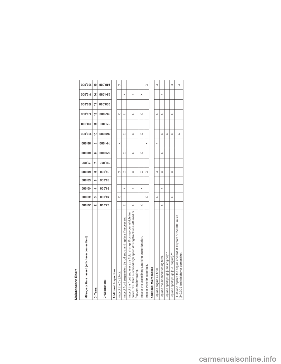
Maintenance ChartMileage or time passed (whichever comes first)
20,00030,000
40,000
50,000
60,000
70,000
80,000 90,000
100,000
110,000
120,000 130,000
140,000
150,000
Or Years: 2 3 4 5 6 7 8 9 10 11 12 13 14 15
Or Kilometers:
32,000
48,000
64,000
80,000
96,000
112,000
128,000 144,000
160,000
176,000
192,000
208,000 224,000
240,000
Additional Inspections
Inspect the CV joints. X X X X X
Inspect front suspension, tie rod ends, and replace if necessary.
XXX X X X X
Inspect the front and rear axle fluid, change if using your vehicle for
police, taxi, fleet, sustained high speed driving/track use, off-road or
frequent trailer towing. XXX X X X X
Inspect the brake linings, parking brake function. X X X X X X X
Inspect transfer case fluid. X X X X
Additional Maintenance
Replace engine air filter. X X X X X
Replace the air conditioning filter. X X X X X X X
Replace spark plugs (3.6L engine).** X
Replace spark plugs (5.7L engine).** X X X X X
Flush and replace the engine coolant at 10 years or 150,000 miles
(240,000 km) whichever comes first. XX
MAINTAINING YOUR VEHICLE
121
Page 127 of 140
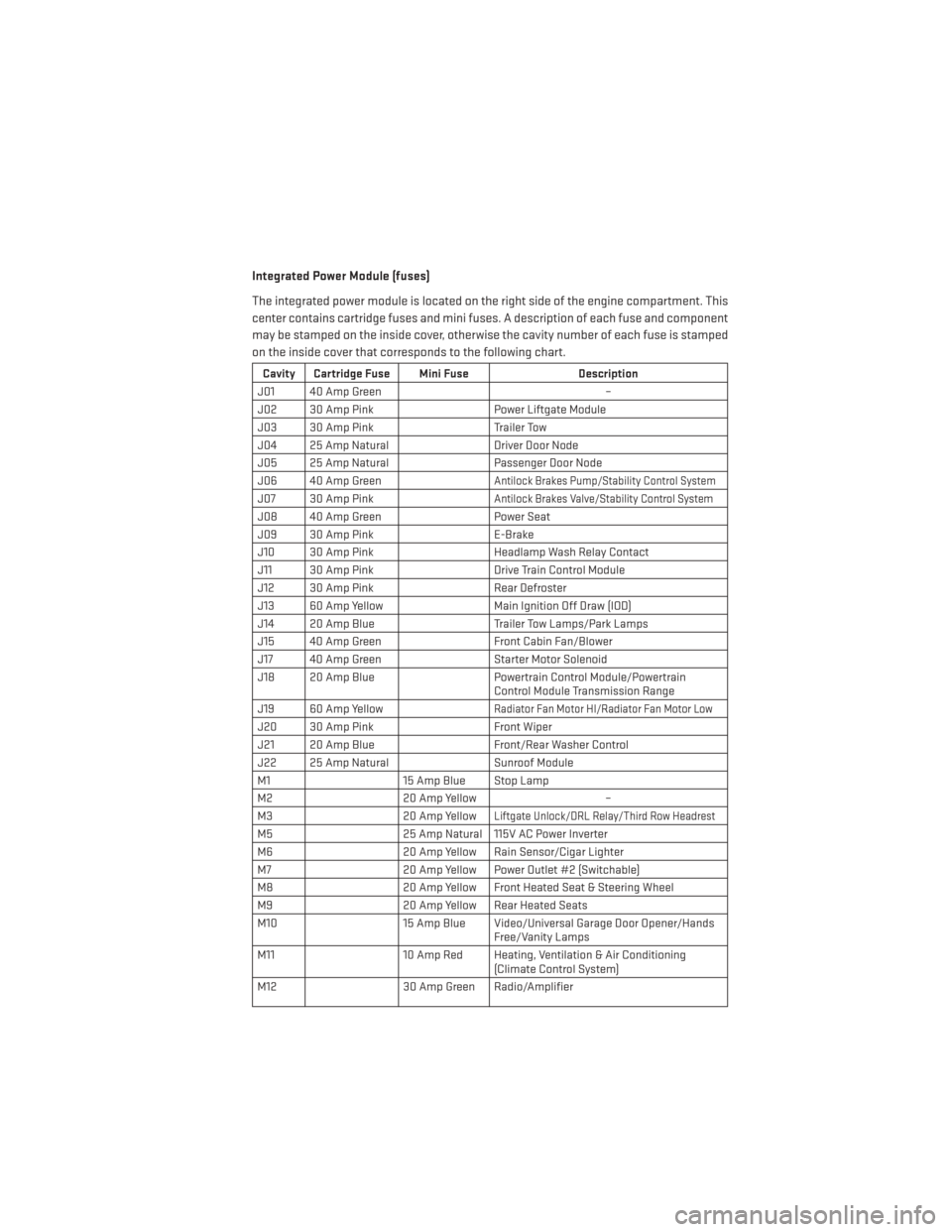
Integrated Power Module (fuses)
The integrated power module is located on the right side of the engine compartment. This
center contains cartridge fuses and mini fuses. A description of each fuse and component
may be stamped on the inside cover, otherwise the cavity number of each fuse is stamped
on the inside cover that corresponds to the following chart.
Cavity Cartridge Fuse Mini FuseDescription
J01 40 Amp Green –
J02 30 Amp Pink Power Liftgate Module
J03 30 Amp Pink Trailer Tow
J04 25 Amp Natural Driver Door Node
J05 25 Amp Natural Passenger Door Node
J06 40 Amp Green
Antilock Brakes Pump/Stability Control System
J07 30 Amp PinkAntilock Brakes Valve/Stability Control System
J08 40 Amp Green Power Seat
J09 30 Amp Pink E-Brake
J10 30 Amp Pink Headlamp Wash Relay Contact
J11 30 Amp Pink Drive Train Control Module
J12 30 Amp Pink Rear Defroster
J13 60 Amp Yellow Main Ignition Off Draw (IOD)
J14 20 Amp Blue Trailer Tow Lamps/Park Lamps
J15 40 Amp Green Front Cabin Fan/Blower
J17 40 Amp Green Starter Motor Solenoid
J18 20 Amp Blue Powertrain Control Module/Powertrain
Control Module Transmission Range
J19 60 Amp Yellow
Radiator Fan Motor HI/Radiator Fan Motor Low
J20 30 Amp Pink Front Wiper
J21 20 Amp Blue Front/Rear Washer Control
J22 25 Amp Natural Sunroof Module
M1 15 Amp Blue Stop Lamp
M2 20 Amp Yellow –
M3 20 Amp Yellow
Liftgate Unlock/DRL Relay/Third Row Headrest
M525 Amp Natural 115V AC Power Inverter
M6 20 Amp Yellow Rain Sensor/Cigar Lighter
M7 20 Amp Yellow Power Outlet #2 (Switchable)
M8 20 Amp Yellow Front Heated Seat & Steering Wheel
M9 20 Amp Yellow Rear Heated Seats
M10 15 Amp Blue Video/Universal Garage Door Opener/Hands
Free/Vanity Lamps
M11 10 Amp Red Heating, Ventilation & Air Conditioning
(Climate Control System)
M12 30 Amp Green Radio/Amplifier
MAINTAINING YOUR VEHICLE
125