lights DODGE DURANGO 2014 3.G Owner's Manual
[x] Cancel search | Manufacturer: DODGE, Model Year: 2014, Model line: DURANGO, Model: DODGE DURANGO 2014 3.GPages: 188, PDF Size: 3.8 MB
Page 119 of 188
The following feature settings are available:
• Display• Clock
• Safety/Assistance • Doors & Locks
• Auto-On Comfort & Remote Start • Engine Off Options
• Phone/Bluetooth® • Audio
• Lights • SiriusXM Setup
• Compass (Uconnect® 5.0) • Trailer Brake
• Suspension • System Information
• Units • Voice
NOTE:
Depending on the vehicles options, feature settings may vary.
EVIC Screen Setup
The following settings allow you to change what information is displayed in the instrument
cluster as well as the location that information is displayed.
• Compass • Fuel Economy Info
• Date • Speed
• Time • Range to Empty
• Outside Temp
Trip A
• Press and release the UP or DOWN arrow button until the Trip A icon is highlighted in the EVIC (Toggle left or right to select Trip A or Trip B). Press and release the OK button to
display the Trip A information.
Trip B
• Press and release the UP or DOWN arrow button until the Trip B icon is highlighted in theEVIC (Toggle left or right to select Trip A or Trip B). Press and release the OK button to
display the Trip B information.
Fuel Economy
Press and release the UP or DOWN arrow button until the Fuel Economy icon is highlighted.
Press the RIGHT arrow button and the next screen will display the following:
• Average Fuel Economy/Miles Per Gallon (MPG Bargraph)
• Range To Empty (RTE)
• Current Miles Per Gallon (MPG)
ELECTRONICS
117
Page 126 of 188
Shifting Procedures
AWD Auto To Low Range
NOTE:
When shifting into or out of LOW RANGE some gear noise may be heard. This noise is
normal and is not detrimental to the vehicle or occupants.
• Shifting can be performed with the vehicle rolling 2 to 3 mph (3 to 5 km/h) or completelystopped. Use either of the following procedures:
Preferred Procedure
1. With the engine running, slow the vehicle to 2 to 3 mph (3 to 5 km/h).
2. Shift the transmission into NEUTRAL.
3. While still rolling, rotate the transfer case control switch to the desired position.
4. After the desired position indicator light is ON (not flashing), shift the transmission back into gear.
Alternate Procedure
1. Bring the vehicle to complete stop.
2. With the ignition switch in the ON position and the engine either OFF or running, shift the transmission into NEUTRAL.
3. Rotate the transfer case control switch to the desired position.
4. After the desired position indicator light is ON (not flashing), shift the transmission back into gear.
NOTE:
• If Steps 1 or 2 of either the Preferred or Alternate Procedure are not satisfied prior to attempting the shift or if they no longer are being met while the shift attempt is in
process, the desired position indicator light will flash continuously while the original
position indicator light is ON, until all requirements have been met.
• The ignition switch must be in the ON position for a shift to take place and for the position indicator lights to be operable. If the ignition switch is not in the ON position, then the
shift will not take place and no position indicator lights will be on or flashing.
WARNING!
• Always engage the parking brake when powering down the vehicle if the “SERV AWD
Warning Light” is illuminated. Not engaging the parking brake may allow the vehicle
to roll which may cause personal injury.
•
You or others could be injured if you leave the vehicle unattended with the transfer case
in the NEUTRAL position without first fully engaging the parking brake. The transfer case
NEUTRAL position disengages both the front and rear driveshafts from the powertrain
and will allow the vehicle to move regardless of the transmission position. The parking
brake should always be applied when the driver is not in the vehicle.
OFF-ROAD CAPABILITIES
124
Page 131 of 188
NOTE:
• Steps 1 through 3 are requirements that must be met before pressing the NEUTRAL (N)button, and must continue to be met until the shift has been completed. If any of these
requirements are not met before pressing the NEUTRAL (N) button or are no longer met
during the shift, the NEUTRAL (N) indicator light will flash continuously until all require-
ments are met or until the NEUTRAL (N) button is released.
• The ignition switch must be in the ON/RUN position for a shift to take place and for the position indicator lights to be operable. If the ignition switch is not in the ON/RUN
position, the shift will not take place and no position indicator lights will be on or flashing.
• A flashing NEUTRAL (N) position indicator light indicates that shift requirements have not been met.
CAUTION!
•Towing with the rear wheels on the ground will cause severe transmission damage.
Damage from improper towing is not covered under the New Vehicle Limited Warranty.
• Front or rear wheel lifts should not be used. Internal damage to the transmission or
transfer case will occur if a front or rear wheel lift is used when recreational towing.
• It is necessary to follow these steps to be certain that the transfer case is fully in NEUTRAL before recreational towing to prevent damage to internal parts.
WARNING!
You or others could be injured if you leave the vehicle unattended with the transfer case
in the NEUTRAL position without first fully engaging the parking brake. The transfer case
NEUTRAL position disengages both the front and rear driveshafts from the powertrain
and will allow the vehicle to move even if the transmission is in PARK. The parking brake
should always be applied when the driver is not in the vehicle.
UTILITY
129
Page 132 of 188
Shifting Out Of NEUTRAL (N)
Use the following procedure to prepare your vehicle for normal usage:
1. Bring the vehicle to a complete stop, leaving it connected to the tow vehicle.
2. Firmly apply the parking brake.
3. Start the engine.
4. Press and hold the brake pedal.
5. Shift the transmission into NEUTRAL.
6. Using a ballpoint pen or similar object, press and hold the recessed transfer caseNEUTRAL (N) button (located by the selector switch) for one second.
7. When the NEUTRAL (N) indicator light turns off, release the NEUTRAL (N) button.
8. After the NEUTRAL (N) button has been released, the transfer case will shift to the position indicated by the selector switch.
9. Shift the transmission into PARK and turn the engine OFF.
10. Release the brake pedal.
11. Disconnect vehicle from the tow vehicle.
12. Start the engine.
13. Press and hold the brake pedal.
14. Release the parking brake.
15. Shift the transmission into DRIVE, release the brake pedal, and check that the vehicle operates normally.
NOTE:
• Steps 1 through 5 are requirements that must be met before pressing the NEUTRAL (N) button, and must continue to be met until the shift has been completed. If any of these
requirements are not met before pressing the NEUTRAL (N) button or are no longer met
during the shift, the NEUTRAL (N) indicator light will flash continuously until all require-
ments are met or until the NEUTRAL (N) button is released.
• The ignition switch must be in the ON/RUN position for a shift to take place and for the position indicator lights to be operable. If the ignition switch is not in the ON/RUN
position, the shift will not take place and no position indicator lights will be on or flashing.
• A flashing NEUTRAL (N) position indicator light indicates that shift requirements have not been met.
UTILITY
130
Page 133 of 188
ROADSIDE ASSISTANCE
Dial toll-free 1-800-521-2779 for U.S. Residents or 1-800-363-4869 for Canadian Residents.
• Provide your name, vehicle identification number, license plate number, and your loca-tion, including the telephone number from which you are calling.
• Briefly describe the nature of the problem and answer a few simple questions.
• You will be given the name of the service provider and an estimated time of arrival. If you feel you are in an “unsafe situation”, please let us know. With your consent, we will
contact local police or safety authorities.
INSTRUMENT CLUSTER WARNING LIGHTS
- Tire Pressure Monitoring System (TPMS) Light
Each tire, including the spare (if provided), should be checked monthly, when cold and
inflated to the inflation pressure recommended by the vehicle manufacturer on the vehicle
placard or tire inflation pressure label. (If your vehicle has tires of a different size than the
size indicated on the vehicle placard or tire inflation pressure label, you should determine
the proper tire inflation pressure for those tires.)
As an added safety feature, your vehicle has been equipped with a Tire Pressure Monitoring
System (TPMS) which display in the Electronic Vehicle Information Center (EVIC) when one
or more of your tires is significantly under-inflated. Accordingly, when the low tire pressure
EVIC display illuminates, you should stop and check your tires as soon as possible, and
inflate them to the proper pressure. Driving on a significantly under-inflated tire causes the
tire to overheat and can lead to tire failure. Under-inflation also reduces fuel efficiency and
tire tread life, and may affect the vehicle’s handling and stopping ability.
IF THE LIGHT STARTS FLASHING INDICATING A LOW TIRE PRESSURE, ADJUST THE AIR
PRESSURE IN THE LOW TIRE TO THE AIR PRESSURE SHOWN ON THE VEHICLE PLACARD
OR TIRE INFLATION PRESSURE LABEL LOCATED ON THE DRIVER'S DOOR.
NOTE:
After inflation, the vehicle may need to be driven for 20 minutes before the flashing light
will turn off.
Please note that the TPMS is not a substitute for proper tire maintenance, and it is the
driver’s responsibility to maintain correct tire pressure, even if under-inflation has not
reached the level to trigger illumination of the TPMS low EVIC display.
Your vehicle has also been equipped with a TPMS malfunction indicator to indicate when
the system is not operating properly. The TPMS malfunction indicator is combined with the
low tire pressure telltale. When the system detects a malfunction, the telltale will flash for
approximately one minute and then remain continuously illuminated. This sequence will
continue each time the vehicle is restarted as long as the malfunction exists.
WHAT TO DO IN EMERGENCIES
131
Page 163 of 188
MAINTENANCE SCHEDULE — GASOLINE ENGINE
Your vehicle is equipped with an automatic oil change indicator system. The oil change indicator
system will remind you that it is time to take your vehicle in for scheduled maintenance.
Based on engine operation conditions, the oil change indicator message will illuminate. This
means that service is required for your vehicle. Operating conditions such as frequent short-
trips, trailer tow, extremely hot or cold ambient temperatures, and E85 fuel usage will influence
when the “Oil Change Required” message is displayed. Severe Operating Conditions can cause
the change oil message to illuminate as early as 3,500 miles (5,600 km) since last reset. Have
your vehicle serviced as soon as possible, within the next 500 miles (805 km).
Your authorized dealer will reset the oil change indicator message after completing the
scheduled oil change. If a scheduled oil change is performed by someone other than your
authorized dealer, the message can be reset by referring to the steps described under “Instru-
ment Cluster Warning Lights” in “What To Do In Emergencies” in this guide or “Electronic
Vehicle Information Center (EVIC)” in “Understanding Your Instrument Panel” in your Owners
Manual on the DVD for further information.
NOTE:
Under no circumstances should oil change intervals exceed 10,000 miles (16,000 km) or
twelve months, whichever comes first.
Severe Duty All Models
Change Engine Oil at 4000 miles (6,500 km) if the vehicle is operated in a dusty and off road
environment. This type of vehicle use is considered Severe Duty.
Once A Month Or Before A Long Trip:
• Check engine oil level
• Check windshield washer fluid level
• Check the tire inflation pressures and look for unusual wear or damage
• Check the fluid levels of the coolant reservoir, brake master cylinder, power steering andtransmission as needed
• Check function of all interior and exterior lights
Required Maintenance
Refer to the Maintenance Schedules on the following pages for required maintenance.
At Every Oil Change Interval As Indicated By Oil Change Indicator System:
• Change oil and filter.
• Rotate the tires. Rotate at the first sign of irregular wear, even if it occurs before the oil
indicator system turns on.
• Inspect battery and clean and tighten terminals as required.
• Inspect automatic transmission fluid if equipped with dipstick.
• Inspect brake pads, shoes, rotors, drums, hoses and park brake.
• Inspect engine cooling system protection and hoses.
• Inspect exhaust system.
• Inspect engine air cleaner if using in dusty or off-road conditions.
MAINTAINING YOUR VEHICLE
161
Page 167 of 188
FUSES
Power Distribution Center (fuses)
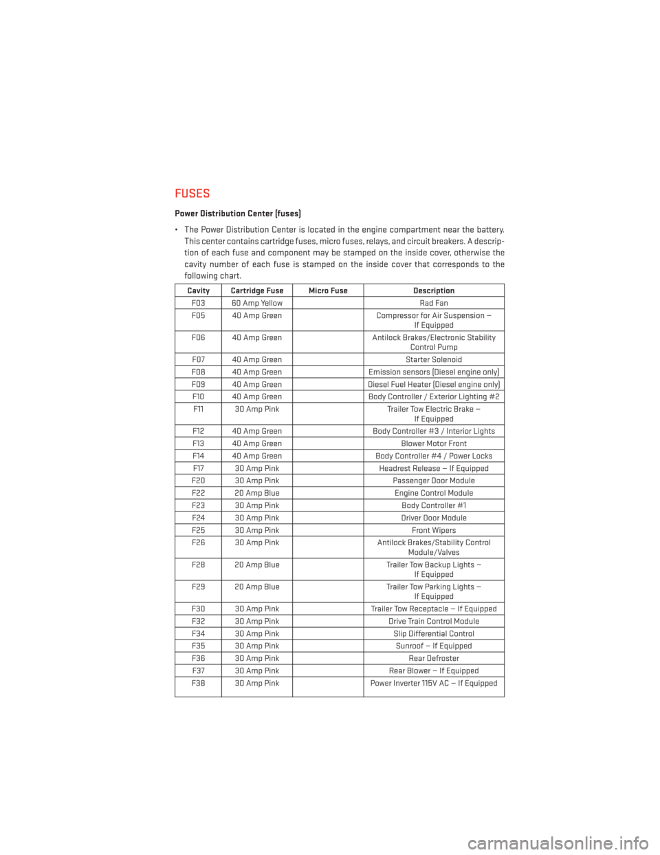
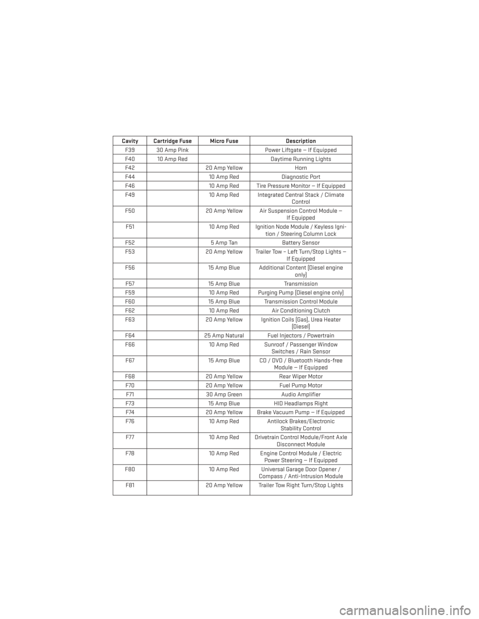
• The Power Distribution Center is located in the engine compartment near the battery.This center contains cartridge fuses, micro fuses, relays, and circuit breakers. A descrip-
tion of each fuse and component may be stamped on the inside cover, otherwise the
cavity number of each fuse is stamped on the inside cover that corresponds to the
following chart.
Cavity Cartridge Fuse Micro Fuse Description
F03 60 Amp Yellow Rad Fan
F05 40 Amp Green Compressor for Air Suspension —
If Equipped
F06 40 Amp Green Antilock Brakes/Electronic Stability
Control Pump
F07 40 Amp Green Starter Solenoid
F08 40 Amp Green Emission sensors (Diesel engine only)
F09 40 Amp Green Diesel Fuel Heater (Diesel engine only)
F10 40 Amp Green Body Controller / Exterior Lighting #2
F11 30 Amp Pink Trailer Tow Electric Brake —
If Equipped
F12 40 Amp Green Body Controller #3 / Interior Lights
F13 40 Amp Green Blower Motor Front
F14 40 Amp Green Body Controller #4 / Power Locks
F17 30 Amp Pink Headrest Release — If Equipped
F20 30 Amp Pink Passenger Door Module
F22 20 Amp Blue Engine Control Module
F23 30 Amp Pink Body Controller #1
F24 30 Amp Pink Driver Door Module
F25 30 Amp Pink Front Wipers
F26 30 Amp Pink Antilock Brakes/Stability Control
Module/Valves
F28 20 Amp Blue Trailer Tow Backup Lights —
If Equipped
F29 20 Amp Blue Trailer Tow Parking Lights —
If Equipped
F30 30 Amp Pink Trailer Tow Receptacle — If Equipped
F32 30 Amp Pink Drive Train Control Module
F34 30 Amp Pink Slip Differential Control
F35 30 Amp Pink Sunroof — If Equipped
F36 30 Amp Pink Rear Defroster
F37 30 Amp Pink Rear Blower — If Equipped
F38 30 Amp Pink Power Inverter 115V AC — If Equipped
MAINTAINING YOUR VEHICLE
165
Page 168 of 188
Cavity Cartridge Fuse Micro FuseDescription
F39 30 Amp Pink Power Liftgate — If Equipped
F40 10 Amp Red Daytime Running Lights
F42 20 Amp Yellow Horn
F44 10 Amp RedDiagnostic Port
F46 10 Amp Red Tire Pressure Monitor — If Equipped
F49 10 Amp Red Integrated Central Stack / Climate
Control
F50 20 Amp Yellow Air Suspension Control Module —
If Equipped
F51 10 Amp Red Ignition Node Module / Keyless Igni-
tion / Steering Column Lock
F52 5 Amp TanBattery Sensor
F53 20 Amp Yellow Trailer Tow – Left Turn/Stop Lights —
If Equipped
F56 15 Amp Blue Additional Content (Diesel engine
only)
F57 15 Amp BlueTransmission
F59 10 Amp Red Purging Pump (Diesel engine only)
F60 15 Amp Blue Transmission Control Module
F62 10 Amp RedAir Conditioning Clutch
F63 20 Amp Yellow Ignition Coils (Gas), Urea Heater
(Diesel)
F64 25 Amp Natural Fuel Injectors / Powertrain
F66 10 Amp Red Sunroof / Passenger Window
Switches / Rain Sensor
F67 15 Amp Blue CD / DVD / Bluetooth Hands-free
Module — If Equipped
F68 20 Amp YellowRear Wiper Motor
F70 20 Amp YellowFuel Pump Motor
F71 30 Amp GreenAudio Amplifier
F73 15 Amp BlueHID Headlamps Right
F74 20 Amp Yellow Brake Vacuum Pump — If Equipped
F76 10 Amp Red Antilock Brakes/Electronic
Stability Control
F77 10 Amp Red Drivetrain Control Module/Front Axle
Disconnect Module
F78 10 Amp Red Engine Control Module / Electric
Power Steering — If Equipped
F80 10 Amp Red Universal Garage Door Opener /
Compass / Anti-Intrusion Module
F81 20 Amp Yellow Trailer Tow Right Turn/Stop Lights
MAINTAINING YOUR VEHICLE
166
Page 174 of 188
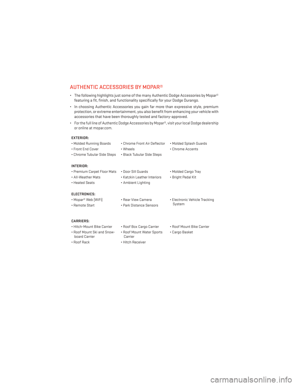
AUTHENTIC ACCESSORIES BY MOPAR®
• The following highlights just some of the many Authentic Dodge Accessories by Mopar®featuring a fit, finish, and functionality specifically for your Dodge Durango.
• In choosing Authentic Accessories you gain far more than expressive style, premium protection, or extreme entertainment, you also benefit from enhancing your vehicle with
accessories that have been thoroughly tested and factory-approved.
•
For the full line of Authentic Dodge Accessories by Mopar®, visit your local Dodge dealership
or online at mopar.com.
EXTERIOR:
• Molded Running Boards • Chrome Front Air Deflector • Molded Splash Guards
• Front End Cover • Wheels• Chrome Accents
• Chrome Tubular Side Steps • Black Tubular Side Steps
INTERIOR:
• Premium Carpet Floor Mats • Door Sill Guards • Molded Cargo Tray
• All-Weather Mats • Katzkin Leather Interiors • Bright Pedal Kit
• Heated Seats • Ambient Lighting
ELECTRONICS:
• Mopar® Web (WiFi) • Rear View Camera • Electronic Vehicle Tracking System
• Remote Start • Park Distance Sensors
CARRIERS:
• Hitch-Mount Bike Carrier • Roof Box Cargo Carrier • Roof Mount Bike Carrier
• Roof Mount Ski and Snow- board Carrier • Roof Mount Water Sports
Carrier • Cargo Basket
• Roof Rack • Hitch Receiver
MOPAR® ACCESSORIES
172
Page 177 of 188
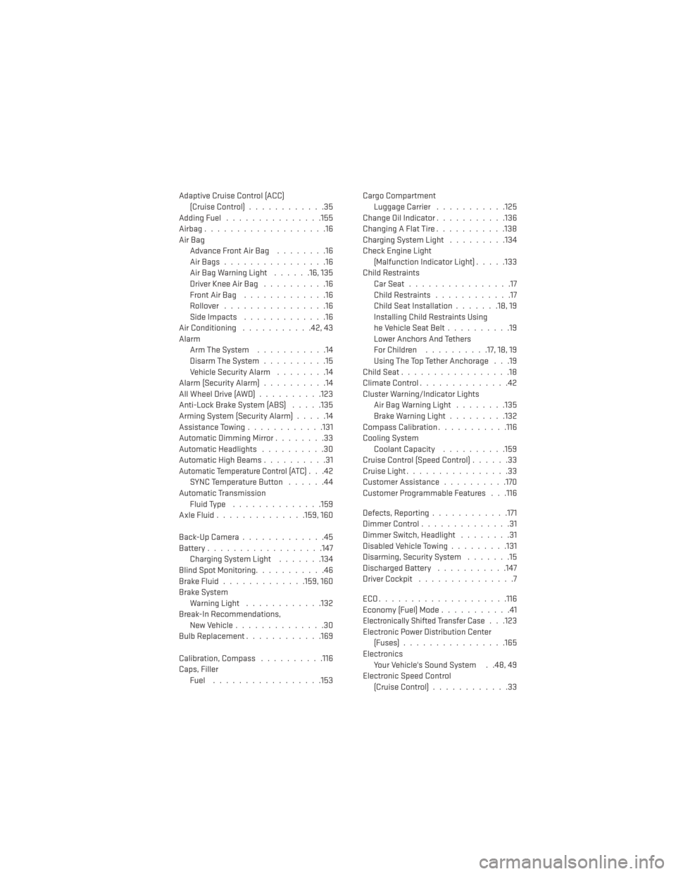
Adaptive Cruise Control (ACC)(Cruise Control) ............35
AddingFuel ...............155
Airbag...................16
Air Bag AdvanceFrontAirBag ........16
AirBags................16
AirBagWarningLight ......16,135
Driver Knee Air Bag ..........16
FrontAirBag .............16
Rollover ................16
Side Impacts .............16
Air Conditioning ...........42,43
Alarm Arm The System ...........14
Disarm The System ..........15
Vehicle Security Alarm ........14
Alarm (Security Alarm) ..........14
AllWheelDrive(AWD)..........123
Anti-Lock Brake System (ABS) .....135
Arming System (Security Alarm) .....14
Assistance Towing ............131
Automatic Dimming Mirror ........33
Automatic Headlights ..........30
Automatic High Beams ..........31
Automatic Temperature Control (ATC)...42
SYNC Temperature Button ......44
Automatic Transmission Fluid Type ..............159
AxleFluid..............159,160
Back-UpCamera.............45
Battery ..................147
Charging System Light .......134
Blind Spot Monitoring ...........46
BrakeFluid.............159,160
Brake System WarningLight ............132
Break-In Recommendations, New Vehicle ..............30
BulbReplacement............169
Calibration, Compass ..........116
Caps, Filler Fuel .................153 Cargo Compartment
Luggage Carrier ...........125
Change Oil Indicator ...........136
ChangingAFlatTire...........138
Charging System Light .........134
Check Engine Light (Malfunction Indicator Light) .....133
Child Restraints CarSeat................17
Child Restraints ............17
Child Seat Installation .......18,19
Installing Child Restraints Using
he Vehicle Seat Belt ..........19
Lower Anchors And Tethers
For Children ..........17, 18, 19
Using The Top Tether Anchorage . . .19
ChildSeat.................18
Climate Control ..............42
Cluster Warning/Indicator Lights AirBagWarningLight ........135
Brake Warning Light .........132
Compass Calibration ...........116
Cooling System Coolant Capacity ..........159
Cruise Control (Speed Control) ......33
Cruise Light ................33
Customer Assistance ..........170
Customer Programmable Features . . .116
Defects, Reporting ............171
DimmerControl..............31
Dimmer Switch, Headlight ........31
Disabled Vehicle Towing .........131
Disarming, Security System .......15
Discharged Battery ...........147
Driver Cockpit ...............7
ECO....................116
Economy (Fuel) Mode ...........41
Electronically Shifted Transfer Case. . .123
Electronic Power Distribution Center (Fuses) ................165
Electronics Your Vehicle's Sound System . .48, 49
Electronic Speed Control (Cruise Control) ............33
INDEX
175