instrument cluster DODGE DURANGO 2014 3.G User Guide
[x] Cancel search | Manufacturer: DODGE, Model Year: 2014, Model line: DURANGO, Model: DODGE DURANGO 2014 3.GPages: 188, PDF Size: 3.8 MB
Page 3 of 188

INTRODUCTION/WELCOME
WELCOME FROM CHRYSLER GROUP LLC . . . 2
CONTROLS AT A GLANCE
DRIVER COCKPIT................6
INSTRUMENT CLUSTER .............8
GETTING STARTED
KEYFOB ....................10
REMOTE START.................11
KEYLESS ENTER-N-GO™ ............11
VEHICLE SECURITY ALARM ..........14
SEATBELT ...................15
SUPPLEMENTAL RESTRAINT SYSTEM (SRS) —
AIRBAGS ....................16
CHILD RESTRAINTS ..............17
FRONT SEATS ..................21
REARSEATS ..................24
POWER FOLDING THIRD ROW HEAD
RESTRAINTS ..................26
HEATED/VENTILATED SEATS .........26
HEATED STEERING WHEEL ..........28
TILT/TELESCOPING STEERING COLUMN . . . 29
OPERATING YOUR VEHICLE
ENGINE BREAK-IN RECOMMENDATIONS . . . 30
HEADLIGHT SWITCH ..............30
TURN SIGNAL/WIPER/WASHER/HIGH BEAM
LEVER ......................31
AUTOMATIC DIMMING MIRRORS .......33
SPEED CONTROL ................33
ADAPTIVE CRUISE CONTROL (ACC) ......35
FORWARD COLLISION WARNING (FCW)
WITHMITIGATION ...............37
ELECTRONIC SHIFTER .............39
AUTOSTICK® ..................40
FUEL ECONOMY (ECO) MODE .........41
AUTOMATIC CLIMATE CONTROLS WITH
TOUCHSCREEN .................42
PARKSENSE® REAR PARK ASSIST ......45
PARKVIEW® REAR BACK-UP CAMERA ....45
BLIND SPOT MONITORING ...........46
POWER SUNROOF ...............46
WIND BUFFETING ................47
ELECTRONICS
YOUR VEHICLE'S SOUND SYSTEM ......48
IDENTIFYING YOUR RADIO ...........50
Uconnect® ACCESS ..............51
Uconnect® 5.0 .................66
Uconnect® 8.4A .................74
Uconnect® 8.4AN ...............94
STEERING WHEEL AUDIO CONTROLS ....115
ELECTRONIC VEHICLE INFORMATION
CENTER (EVIC) .................115
PROGRAMMABLE FEATURES .........116UNIVERSAL GARAGE DOOR OPENER
(HomeLink®)
..................118
POWER INVERTER ..............120
POWER OUTLET ................121
OFF-ROAD CAPABILITIES
ALL-WHEEL DRIVE OPERATION .......123
UTILITY
ROOF LUGGAGE RACK............125
TRAILER TOWING WEIGHTS
(MAXIMUM TRAILER WEIGHT RATINGS) . . 125
RECREATIONAL TOWING
(BEHIND MOTORHOME, ETC.) ........126
WHAT TO DO IN EMERGENCIES
ROADSIDE ASSISTANCE...........131INSTRUMENT CLUSTER WARNING LIGHTS . . . 131IF YOUR ENGINE OVERHEATS .........137
JACKING AND TIRE CHANGING .......138
BATTERY LOCATION ..............147
JUMP-STARTING ...............147
MANUAL PARK RELEASE 8-SPEED .....150
TOWING A DISABLED VEHICLE ........151
FREEING A STUCK VEHICLE .........152
EVENT DATA RECORDER (EDR) ........153
CAP-LESS FUEL FILL FUNNEL ........153
MAINTAINING YOUR VEHICLE
OPENING THE HOOD.............154
ADDING FUEL .................155
ENGINE COMPARTMENT ...........157
FLUIDS AND CAPACITIES ...........159
MAINTENANCE SCHEDULE —
GASOLINE ENGINE ...............161
MAINTENANCE RECORD ...........164
FUSES .....................165
TIRE PRESSURES ...............168
WHEEL AND WHEEL TRIM CARE ......169
EXTERIOR BULBS ..............169
CUSTOMER ASSISTANCE
CHRYSLER GROUP LLC
CUSTOMER CENTER .............170
CHRYSLER CANADA INC.
CUSTOMER CENTER .............170
ASSISTANCE FOR THE HEARING IMPAIRED..170
PUBLICATIONS ORDERING ..........170
REPORTING SAFETY DEFECTS IN THE
UNITEDSTATES ................171
MOPAR® ACCESSORIES
AUTHENTIC ACCESSORIES BY MOPAR® . . . 172
FREQUENTLY ASKED QUESTIONS
FREQUENTLY ASKED QUESTIONS ......173
INDEX....................175
TABLE OF CONTENTS
Page 8 of 188
DRIVER COCKPIT
1. Power Mirror Controls
2. Headlight Switch pg. 30
3. Paddle Shifter’s (AutoStick®) pg. 40
4. Instrument Cluster pg. 8
5. Electronic Vehicle Information Center (EVIC) Display
6. Engine Start/Stop Button (Behind Steering Wheel) pg. 13
7. Audio System (Touchscreen Radio Shown) pg. 48
8. Passenger Power Window Controls
9. Glove Compartment
10. Audio System Control Knob pg. 66
CONTROLS AT A GLANCE
6
Page 10 of 188
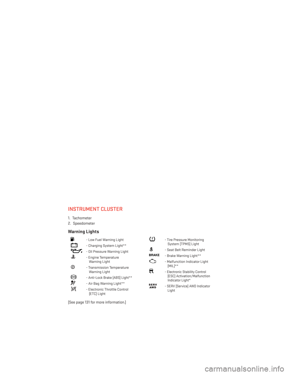
INSTRUMENT CLUSTER
1. Tachometer
2. Speedometer
Warning Lights
- Low Fuel Warning Light
- Charging System Light**
- Oil Pressure Warning Light
- Engine TemperatureWarning Light
- Transmission TemperatureWarning Light
-Anti-Lock Brake (ABS) Light**
- Air Bag Warning Light**
- Electronic Throttle Control(ETC) Light
- Tire Pressure MonitoringSystem (TPMS) Light
- Seat Belt Reminder Light
BRAKE- Brake Warning Light**
- Malfunction Indicator Light(MIL)**
-Electronic Stability Control(ESC) Activation/Malfunction
Indicator Light*
-SERV (Service) AWD Indicator Light
(See page 131 for more information.)
CONTROLS AT A GLANCE
8
Page 35 of 188
AUTOMATIC DIMMING MIRRORS
• The rearview and driver side exterior mirror automatically adjusts for headlight glarefrom vehicles behind you.
• You can turn the feature on or off when the Automatic Dimming Mirror feature is selected through the programmable features in the Uconnect® system. Refer to “Uconnect®
Settings” in “Understanding Your Instrument Panel” in the Owner's Manual on the DVD for
further details.
SPEED CONTROL
The Speed Control switches are located on the right side of the steering wheel.
Cruise ON/OFF
• Push the ON/OFF buttonto activate
the Speed Control.
CRUISE CONTROL READY will appear on the
instrument cluster to indicate the Speed
Control is on.
• Push the ON/OFF button
a second
time to turn the system off.
CRUISE CONTROL OFF will appear on the
instrument cluster to indicate the Speed
Control is off.
SET
• With the Speed Control on, push and re- lease the SET+ or SET- button to set a
desired speed.
Once a speed has been set a message
CRUISE CONTROL SET TO MPH/KM will ap-
pear indicating what speed was set. An indicator CRUISE will also appear and stay on in the
instrument cluster when the speed is set.
Accel/Decel
To Increase Speed
• When the Electronic Speed Control is set, you can increase speed by pushing the SET +
button.
The speed increment shown is dependant on the speed of U.S. (mph) or Metric (km/h) units:
U.S. Speed (mph)
• Pressing the SET +button once will result i n a 1 mph increase in set speed. Each
subsequent tap of the button results in an increase of 1 mph.
• If the button is continually pressed, the set speed will continue to increase until the button is released, then the new set speed will be established.
Speed Control Switches
1 — Push Cancel
2 — Push Set+/Accel
3 — Push Resume
4 — Push On/Off
5 — Push Set-/Decel
OPERATING YOUR VEHICLE
33
Page 37 of 188
ADAPTIVE CRUISE CONTROL (ACC)
If your vehicle is equipped with adaptive cruise
control the controls operate exactly the same
as the normal (fixed speed) speed control with
one difference. You can set a specified distance
you would like to maintain between you and the
vehicle in front of you.
If the ACC sensor detects a vehicle ahead,
ACC will apply limited braking or accelera-
tion automatically to maintain a preset fol-
lowing distance, while matching the speed
of the vehicle ahead.
If the sensor does not detect a vehicle ahead
of you, ACC will maintain a fixed set speed.
ACC ON/OFF
• Push and release the Adaptive CruiseControl (ACC) ON/OFF button.
ACC READY will appear on the instrument cluster to indicate the ACC is on.
• Push and release the Adaptive Cruise Control (ACC) ON/OFF button a second time to turn the system off.
Adaptive Cruise Control (ACC) Off will appear on the instrument cluster to indicate the ACC is off.
Distance Setting (ACC Only)
The specified following distance for ACC can be set by varying the distance setting between
four bars (longest), three bars (long), two bars (medium) and one bar (short). Using this
distance setting and the vehicle speed, ACC calculates and sets the distance to the vehicle
ahead. This distance setting displays in the EVIC.
•
To increase the distance setting, press the Distance Setting—Increase button and release.
Each time the button is pressed, the distance setting increases by one bar (longer).
•To decrease the distance setting, press the Distance Setting—Decrease button and release.
Each time the button is pressed, the distance setting decreases by one bar (shorter).
ACC Operation At Stop
If the ACC system brings your vehicle to a standstill while following a target vehicle, if the
target vehicle starts moving within two seconds of your vehicle coming to a standstill, your
vehicle will resume motion without the need for any driver action.
If the target vehicle does not start moving within two seconds of your vehicle coming to a
standstill, the ACC with Stop system will cancel and the brakes will ramp-out. Driver
intervention will be required at this moment.
Adaptive Cruise Switches
1 — Adaptive Cruise Control (ACC) On/Off
2 — Distance Setting – Decrease
3 — Distance Setting – Increase
OPERATING YOUR VEHICLE
35
Page 42 of 188
AUTOSTICK®
AutoStick® is a driver-interactive transmis-
sion feature providing manual shift control,
giving you more control of the vehicle.
AutoStick® allows you to maximize engine
braking, eliminate undesirable upshifts and
downshifts, and improve overall vehicle per-
formance. This system can also provide you
with more control during passing, city driving, cold slippery conditions, mountain driving,
trailer towing, and many other situations.
Operation
• When the transmission is in DRIVE, it will operate automatically, shifting between theeight available gears. To engage AutoStick®, simply tap one of the steering wheel-
mounted shift paddles (+/-). Tapping (-) to enter AutoStick® will downshift the transmis-
sion to the next lower gear, while using (+) to enter AutoStick® will retain the current gear.
When AutoStick® is active, the current transmission gear is displayed in the instrument
cluster.
In AutoStick® mode, the transmission will shift up or down when (+/-) is manually selected
by the driver, unless an engine lugging or overspeed condition would result.
NOTE:
To disengage AutoStick® mode, press and hold the (+) shift paddle until "D" is once again
displayed in the instrument cluster. You can shift in or out of AutoStick® mode at any time
without taking your foot off the accelerator pedal.
WARNING!
Do not downshift for additional engine braking on a slippery surface. The drive wheels
could lose their grip and the vehicle could skid, causing a collision or personal injury.
OPERATING YOUR VEHICLE
40
Page 47 of 188
PARKSENSE® REAR PARK ASSIST
The four ParkSense® sensors, located in the rear fascia/bumper, monitor the area behind
the vehicle that is within the sensors’ field of view.
The sensors can detect obstacles from approximately 12 in (30 cm) up to 79 in (200 cm)
from the rear bumper while the vehicle is in REVERSE, a warning will display in the Electronic
Vehicle Information Center (EVIC) and a chime will sound (when Sound and Display is
selected from the Customer Programmable Features section of the Uconnect® System
screen). As the vehicle moves closer to the object, the chime rate will change from single
1/2 second tone, to slow, to fast, to continuous.
Cleaning The ParkSense® Sensors
If “CLEAN PARK ASSIST SENSORS” appears in the Electronic Vehicle Information Center
(EVIC), clean the ParkSense® sensors with water, car wash soap and a soft cloth. Do not use
rough or hard cloths. Do not scratch or poke the sensors. Otherwise, you could damage the
sensors.
NOTE:
When the Instrument Cluster reads either Clean Sensor or Blinded, please clean off the
bumper sensors to see if the condition is corrected.
PARKVIEW® REAR BACK-UP CAMERA
You can see an on-screen image of the rear of your vehicle whenever the shift lever/gear
selector is put into REVERSE. The ParkView® Rear Back-Up Camera image will be displayed
on the radio display screen, located on the center stack of the instrument panel.
If the radio display screen appears foggy, clean the camera lens located on the liftgate.
WARNING!
Drivers must be careful when backing up; even when using the ParkView® Rear Back-Up
Camera. Always check carefully behind your vehicle, and be sure to check for pedestri-
ans, animals, other vehicles, obstructions, or blind spots before backing up. You must
continue to pay attention while backing up. Failure to do so can result in serious injury or
death.
OPERATING YOUR VEHICLE
45
Page 117 of 188
STEERING WHEEL AUDIO CONTROLS
The steering wheel audio controls are located on the rear surface of the steering wheel.
Right Switch
• Press the switch up or down to increase ordecrease the volume.
• Press the button in the center to change modes AM/FM/CD/SXM.
Left Switch
• Press the switch up or down to search forthe next listenable station or select the
next or previous CD track.
•
Press the button in the center to select the
next preset station (radio) or to change CDs
if equipped with a CD Changer.
ELECTRONIC VEHICLE INFORMATION CENTER (EVIC)
The EVIC features a driver interactive display that is located in the instrument cluster.
Pressing the controls on the left side of the steering wheel allows the driver to select vehicle
information and Personal Settings. For additional information, refer to Programmable
Features in this guide.
•
Press and release the UPbutton to
scroll upward through the main menus
(Speedometer, MPH/km/h, Vehicle Info,
Terrain, Driver Assist, Fuel Economy, Trip A,
Trip B, Audio, Stored Messages, Screen
Set Up).
• Press and release the DOWNbutton
to scroll downward through the main
menu and submenus (Speedometer,
MPH/km/h, Vehicle Info, Terrain, Driver
Assist, Fuel Economy, Trip A, Trip B, Audio,
Stored Messages, Screen Set Up).
• Press and release the RIGHT
button
to access the information screens or
sub-menu screens of a main menu item.
• Press the BACK/LEFT
button to
access the information screens or sub-
menu screens of a main menu item.
• Press the OKbutton to access/select the information screens or sub-menu screens of a
main menu item. Press and hold the OK button for two seconds to reset displayed/
selected features that can be reset.1 — EVIC Controls
ELECTRONICS
115
Page 119 of 188
The following feature settings are available:
• Display• Clock
• Safety/Assistance • Doors & Locks
• Auto-On Comfort & Remote Start • Engine Off Options
• Phone/Bluetooth® • Audio
• Lights • SiriusXM Setup
• Compass (Uconnect® 5.0) • Trailer Brake
• Suspension • System Information
• Units • Voice
NOTE:
Depending on the vehicles options, feature settings may vary.
EVIC Screen Setup
The following settings allow you to change what information is displayed in the instrument
cluster as well as the location that information is displayed.
• Compass • Fuel Economy Info
• Date • Speed
• Time • Range to Empty
• Outside Temp
Trip A
• Press and release the UP or DOWN arrow button until the Trip A icon is highlighted in the EVIC (Toggle left or right to select Trip A or Trip B). Press and release the OK button to
display the Trip A information.
Trip B
• Press and release the UP or DOWN arrow button until the Trip B icon is highlighted in theEVIC (Toggle left or right to select Trip A or Trip B). Press and release the OK button to
display the Trip B information.
Fuel Economy
Press and release the UP or DOWN arrow button until the Fuel Economy icon is highlighted.
Press the RIGHT arrow button and the next screen will display the following:
• Average Fuel Economy/Miles Per Gallon (MPG Bargraph)
• Range To Empty (RTE)
• Current Miles Per Gallon (MPG)
ELECTRONICS
117
Page 133 of 188
ROADSIDE ASSISTANCE
Dial toll-free 1-800-521-2779 for U.S. Residents or 1-800-363-4869 for Canadian Residents.
• Provide your name, vehicle identification number, license plate number, and your loca-tion, including the telephone number from which you are calling.
• Briefly describe the nature of the problem and answer a few simple questions.
• You will be given the name of the service provider and an estimated time of arrival. If you feel you are in an “unsafe situation”, please let us know. With your consent, we will
contact local police or safety authorities.
INSTRUMENT CLUSTER WARNING LIGHTS
- Tire Pressure Monitoring System (TPMS) Light
Each tire, including the spare (if provided), should be checked monthly, when cold and
inflated to the inflation pressure recommended by the vehicle manufacturer on the vehicle
placard or tire inflation pressure label. (If your vehicle has tires of a different size than the
size indicated on the vehicle placard or tire inflation pressure label, you should determine
the proper tire inflation pressure for those tires.)
As an added safety feature, your vehicle has been equipped with a Tire Pressure Monitoring
System (TPMS) which display in the Electronic Vehicle Information Center (EVIC) when one
or more of your tires is significantly under-inflated. Accordingly, when the low tire pressure
EVIC display illuminates, you should stop and check your tires as soon as possible, and
inflate them to the proper pressure. Driving on a significantly under-inflated tire causes the
tire to overheat and can lead to tire failure. Under-inflation also reduces fuel efficiency and
tire tread life, and may affect the vehicle’s handling and stopping ability.
IF THE LIGHT STARTS FLASHING INDICATING A LOW TIRE PRESSURE, ADJUST THE AIR
PRESSURE IN THE LOW TIRE TO THE AIR PRESSURE SHOWN ON THE VEHICLE PLACARD
OR TIRE INFLATION PRESSURE LABEL LOCATED ON THE DRIVER'S DOOR.
NOTE:
After inflation, the vehicle may need to be driven for 20 minutes before the flashing light
will turn off.
Please note that the TPMS is not a substitute for proper tire maintenance, and it is the
driver’s responsibility to maintain correct tire pressure, even if under-inflation has not
reached the level to trigger illumination of the TPMS low EVIC display.
Your vehicle has also been equipped with a TPMS malfunction indicator to indicate when
the system is not operating properly. The TPMS malfunction indicator is combined with the
low tire pressure telltale. When the system detects a malfunction, the telltale will flash for
approximately one minute and then remain continuously illuminated. This sequence will
continue each time the vehicle is restarted as long as the malfunction exists.
WHAT TO DO IN EMERGENCIES
131