engine DODGE DURANGO 2015 3.G Owner's Manual
[x] Cancel search | Manufacturer: DODGE, Model Year: 2015, Model line: DURANGO, Model: DODGE DURANGO 2015 3.GPages: 689, PDF Size: 20.05 MB
Page 192 of 689
HEATED STEERING WHEEL — IF EQUIPPED
The steering wheel contains a heating element that helps
warm your hands in cold weather. The heated steering
wheel has only one temperature setting. Once the heated
steering wheel has been turned on it will operate for up
to 80 minutes before automatically shutting off. The
heated steering wheel can shut off early or may not turn
on when the steering wheel is already warm.
The heated steering wheel control button is located
within the Uconnect® system. You can gain access to the
control button through the climate screen or the controls
screen.
•Press the heated steering wheel buttononce to
turn the heating element ON.
•Press the heated steering wheel buttona second
time to turn the heating element OFF.
NOTE:The engine must be running for the heated
steering wheel to operate.
Vehicles Equipped With Remote Start
On models that are equipped with remote start, the
heated steering wheel can be programmed to come on
during a remote start through the Uconnect® system.
Refer to “Uconnect® Settings” in “Understanding Your
Instrument Panel” for further information.
190 UNDERSTANDING THE FEATURES OF YOUR VEHICLE
Page 207 of 689
•If the button is continually pushed, the set speed will
continue to decrease in 5 mph decrements until the
button is released. The decrease in set speed is re-
flected in the DID.
Metric Speed (km/h)
•Pushing the SET-button once will result in a 1 km/h
decrease in set speed. Each subsequent tap of the
button results in a decrease of 1 km/h.
•If the button is continually pushed, the set speed will
continue to decrease in 10 km/h decrements until the
button is released. The decrease in set speed is re-
flected in the DID.
NOTE:
•When you override and push the SET+button or SET
-buttons, the new Set Speed will be the current speed
of the vehicle.
•When you use the SET-button to decelerate, if the
engine’s braking power does not slow the vehicle
sufficiently to reach the set speed, the brake system
will automatically slow the vehicle.
•The ACC system applies the brake down to a full stop
when following a target vehicle. If an ACC host vehicle
follows a target vehicle to a standstill, the host vehicle
will release the vehicle brakes two seconds after com-
ing to a full stop.
•The ACC system maintains set speed when driving up
hill and down hill. However, a slight speed change on
moderate hills is normal. In addition, downshifting
may occur while climbing uphill or descending down-
hill. This is normal operation and necessary to main-
tain set speed. When driving up hill and down hill, the
ACC system will cancel if the braking temperature
exceeds normal range (overheated).
3
UNDERSTANDING THE FEATURES OF YOUR VEHICLE 205
Page 261 of 689
CAUTION!
•Many accessories that can be plugged in draw
power from the vehicle’s battery, even when not in
use (i.e., cellular phones, etc.). Eventually, if
plugged in long enough, the vehicle’s battery will
discharge sufficiently to degrade battery life and/or
prevent the engine from starting.
•Accessories that draw higher power (i.e., coolers,
vacuum cleaners, lights, etc.) will degrade the bat-
tery even more quickly. Only use these intermit-
tently and with greater caution.
•After the use of high power draw accessories, or
long periods of the vehicle not being started (with
accessories still plugged in), the vehicle must be
driven a sufficient length of time to allow the
generator to recharge the vehicle’s battery.
POWER INVERTER — IF EQUIPPED
There is a 115 Volt, 150 Watt inverter outlet located on the
back of the center console to convert DC current to AC
current. This outlet can power cellular phones, electron-
ics and other low power devices requiring power up to
150 Watts. Certain high-end video games, such as Play-
station3 and XBox360 will exceed this power limit, as will
most power tools.
3
UNDERSTANDING THE FEATURES OF YOUR VEHICLE 259
Page 278 of 689
mirrors (if equipped). An indicator in the button will
illuminate when the rear window defroster is on. The
rear window defroster automatically turns off after ap-
proximately 10 minutes. For an additional five minutes of
operation, push the button a second time.
NOTE:To prevent excessive battery drain, use the rear
window defroster only when the engine is operating.
CAUTION!
Failure to follow these cautions can cause damage to
the heating elements:
•Use care when washing the inside of the rear
window. Do not use abrasive window cleaners on
the interior surface of the window. Use a soft cloth
and a mild washing solution, wiping parallel to the
heating elements. Labels can be peeled off after
soaking with warm water.
(Continued)
CAUTION!(Continued)
•Do not use scrapers, sharp instruments, or abrasive
window cleaners on the interior surface of the
window.
•Keep all objects a safe distance from the window.
ROOF LUGGAGE RACK — IF EQUIPPED
The crossbars and side rails are designed to carry weight
on vehicles equipped with a luggage rack.The load must
not exceed 150 lbs (68 kg), and should be uniformly
distributed over the luggage rack crossbars.
The crossbars on your vehicle are delivered stowed
within the roof rack side rails. Crossbars should always
be used whenever cargo is placed on the roof rack. Check
the straps frequently to be sure that the load remains
securely attached.
276 UNDERSTANDING THE FEATURES OF YOUR VEHICLE
Page 289 of 689
UNDERSTANDING YOUR INSTRUMENT PANEL
CONTENTS
!INSTRUMENT PANEL FEATURES..........290
!INSTRUMENT CLUSTER.................291
!INSTRUMENT CLUSTER DESCRIPTIONS.....292
!DRIVER INFORMATION DISPLAY (DID).....301
▫DID Displays........................303
▫Engine Oil Life Reset..................305
▫DID Messages.......................306
▫DID White Telltales....................308
▫DID Amber Telltales...................308
▫DID Red Telltales......................309
▫DID Green Telltales....................312
▫DID Selectable Menu Items..............312
▫Screen Setup Driver Selectable Items........316
!Uconnect® SETTINGS....................317
▫Buttons On The Faceplate................318
▫Buttons On The Touchscreen..............319
▫Customer Programmable Features —
Uconnect® 5.0 Personal Settings...........319
▫Customer Programmable Features —
Uconnect® 8.4 Personal Settings...........334
4
Page 294 of 689
INSTRUMENT CLUSTER DESCRIPTIONS
1. Tachometer
Indicates the engine speed in revolutions per minute
(RPM x 1000).
2. Seat Belt Reminder Light
When the ignition switch is first turned to the
ON/RUN position, this light will turn on for four
to eight seconds as a bulb check. During the bulb
check, if the driver’s seat belt is unbuckled, a chime will
sound. After the bulb check or when driving, if the driver
or front passenger seat belt remains unbuckled, the Seat
Belt Indicator Light will flash or remain on continuously.
Refer to “Occupant Restraints” in “Things To Know
Before Starting Your Vehicle” for further information.
3. Anti-Lock Brake (ABS) Light
This light monitors the Anti-Lock Brake System
(ABS). The light will turn on when the ignition
switch is turned to the ON/RUN position and
may stay on for as long as four seconds.
If the ABS light remains on or turns on while driving, it
indicates that the Anti-Lock portion of the brake system
is not functioning and that service is required. However,
the conventional brake system will continue to operate
normally if the BRAKE warning light is not on.
If the ABS light is on, the brake system should be serviced
as soon as possible to restore the benefits of Anti-Lock
brakes. If the ABS light does not turn on when the
ignition switch is turned to the ON/RUN position, have
the light inspected by an authorized dealer.
4. High Beam Indicator
Indicates that headlights are on high beam.
292 UNDERSTANDING YOUR INSTRUMENT PANEL
Page 295 of 689
5. Front Fog Light Indicator — If Equipped
This indicator will illuminate when the front fog
lights are on.
6. Selectable DID Information
This area of the cluster will display selectable informa-
tion such as compass, outside temperature, etc. For
further information, refer to “Driver Information Display
(DID) — If Equipped” of your Owner ’s Manual for more
information.
7. Turn Signal Indicator
The arrows will flash with the exterior turn
signals when the turn signal lever is operated.
A tone will chime, and an DID message will
appear if either turn signal is left on for more
than 1 mile (1.6 km).
NOTE:If either indicator flashes at a rapid rate, check
for a defective outside light bulb.
8. Speedometer
Indicates vehicle speed.
9. Selectable DID Information
This area of the cluster will display selectable informa-
tion such as compass, outside temperature, etc. For
further information, refer to “Driver Information Display
(DID) — If Equipped” of your Owner ’s Manual for more
information.
10. Malfunction Indicator Light (MIL)
The Malfunction Indicator Light (MIL) is part of
an onboard diagnostic system called OBD II that
monitors engine and automatic transmission con-
trol systems. The light will illuminate when the key is in
the ON/RUN position before engine start. If the bulb
does not come on when turning the key from OFF to
ON/RUN, have the condition checked promptly.
4
UNDERSTANDING YOUR INSTRUMENT PANEL 293
Page 296 of 689
Certain conditions, poor fuel quality, may illuminate the
light after engine start. The vehicle should be serviced if
the light stays on through several of your typical driving
cycles. In most situations, the vehicle will drive normally
and will not require towing.
CAUTION!
Prolonged driving with the Malfunction Indicator
Light (MIL) on could cause damage to the engine
control system. It also could affect fuel economy and
driveability. If the MIL is flashing, severe catalytic
converter damage and power loss will soon occur.
Immediate service is required.
WARNING!
A malfunctioning catalytic converter, as referenced
above, can reach higher temperatures than in normal
operating conditions. This can cause a fire if you
drive slowly or park over flammable substances such
as dry plants, wood, cardboard, etc. This could result
in death or serious injury to the driver, occupants or
others.
11. Temperature Gauge
The temperature gauge shows engine coolant tempera-
ture. Any reading within the normal range indicates that
the engine cooling system is operating satisfactorily.
The gauge pointer will likely indicate a higher tempera-
ture when driving in hot weather, up mountain grades,
or when towing a trailer. It should not be allowed to
exceed the upper limits of the normal operating range.
294 UNDERSTANDING YOUR INSTRUMENT PANEL
Page 297 of 689
CAUTION!
Driving with a hot engine cooling system could
damage your vehicle. If the temperature gauge reads
“H” pull over and stop the vehicle. Idle the vehicle
with the air conditioner turned off until the pointer
drops back into the normal range. If the pointer
remains on the “H” and you hear continuous chimes,
turn the engine off immediately and call an autho-
rized dealer for service.
WARNING!
A hot engine cooling system is dangerous. You or
others could be badly burned by steam or boiling
coolant. You may want to call an authorized dealer
for service if your vehicle overheats. If you decide to
look under the hood yourself, see “Maintaining Your
(Continued)
WARNING!(Continued)
Vehicle”. Follow the warnings under the Cooling
System Pressure Cap paragraph.
12. Brake Warning Light
This light monitors various brake functions,
including brake fluid level and parking brake
application. If the brake light turns on, it may
indicate that the parking brake is applied, that
the brake fluid level is low, or that there is a
problem with the anti-lock brake system reser-
voir.
If the light remains on when the parking brake has been
disengaged, and the fluid level is at the full mark on the
master cylinder reservoir, it indicates a possible brake
hydraulic system malfunction or that a problem with the
Brake Booster has been detected by the Anti-Lock Brake
System (ABS) / Electronic Stability Control (ESC) system.
4
UNDERSTANDING YOUR INSTRUMENT PANEL 295
Page 302 of 689
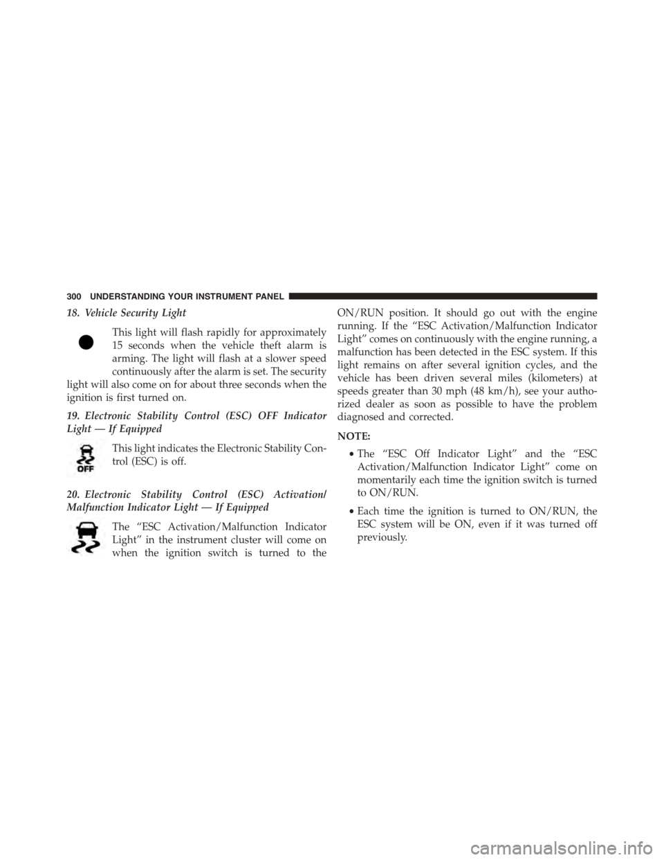
18. Vehicle Security Light
This light will flash rapidly for approximately
15 seconds when the vehicle theft alarm is
arming. The light will flash at a slower speed
continuously after the alarm is set. The security
light will also come on for about three seconds when the
ignition is first turned on.
19. Electronic Stability Control (ESC) OFF Indicator
Light — If Equipped
This light indicates the Electronic Stability Con-
trol (ESC) is off.
20. Electronic Stability Control (ESC) Activation/
Malfunction Indicator Light — If Equipped
The “ESC Activation/Malfunction Indicator
Light” in the instrument cluster will come on
when the ignition switch is turned to the
ON/RUN position. It should go out with the engine
running. If the “ESC Activation/Malfunction Indicator
Light” comes on continuously with the engine running, a
malfunction has been detected in the ESC system. If this
light remains on after several ignition cycles, and the
vehicle has been driven several miles (kilometers) at
speeds greater than 30 mph (48 km/h), see your autho-
rized dealer as soon as possible to have the problem
diagnosed and corrected.
NOTE:
•The “ESC Off Indicator Light” and the “ESC
Activation/Malfunction Indicator Light” come on
momentarily each time the ignition switch is turned
to ON/RUN.
•Each time the ignition is turned to ON/RUN, the
ESC system will be ON, even if it was turned off
previously.
300 UNDERSTANDING YOUR INSTRUMENT PANEL