air condition DODGE DURANGO 2015 3.G User Guide
[x] Cancel search | Manufacturer: DODGE, Model Year: 2015, Model line: DURANGO, Model: DODGE DURANGO 2015 3.GPages: 236, PDF Size: 35.01 MB
Page 19 of 236
•TheAdvancedFrontAirBagswillnotdeployinallfrontalcollisions,includingsome
that may produce substantial vehicle damage — for example, some pole collisions,
truck underrides, and angle offset collisions.
•Ontheotherhand,dependingonthetypeandlocationofimpact,AdvancedFrontAir
Bags may deploy in crashes with little vehicle front-end damage but that produce a
severe initial deceleration.
•Becauseairbagsensorsmeasurevehicledecelerationovertime,vehiclespeedand
damage by themselves are not good indicators of whether or not an air bag should have
deployed.
•Seatbeltsarenecessaryforyourprotectioninallcollisions,andalsoareneededtohelp
keep you in position, away from an inflating air bag.
•Theairbagsmustbereadytoinflateforyourprotectioninacollision.TheOccupant
Restraint Controller (ORC) monitors the internal circuits and interconnecting wiring
associated with air bag system electrical components.
•TheORCturnsontheAirBagWarningLightintheinstrumentpanelforapproximately
four to eight seconds for a self-check when the ignition switch is first turned to the
ON/RUN position. After the self-check, the Air Bag Warning Light will turn off. If the
ORC detects a malfunction in any part of the system, it turns on the Air Bag Warning
Light, either momentarily or continuously. A single chime will sound to alert you if the
light comes on again after initial startup.
•TheORCmonitorsthereadinessoftheelectronicpartsoftheairbagsystemwhenever
the ignition switch is in the START or ON/RUN position. If the ignition switch is in the
OFF position or in the ACC position, the air bag system is not on and the air bags will
not inflate.
•IftheAirBagWarningLightintheinstrumentpanelisnotonduringthefourtoeight
seconds when the ignition switch is first turned to the ON/RUN position, stays on, or
turns on while driving, have the vehicle serviced by an authorized service center
immediately.
NOTE:
If the speedometer, tachometer, or any engine related gauges are not working, the
Occupant Restraint Controller (ORC) may also be disabled. In this condition the air bags
may not be ready to inflate for your protection. Have an authorized dealer service the air
bag system immediately.
•Afteranycollision,thevehicleshouldbetakentoanauthorizeddealerimmediately.
•Donotdriveyourvehicleaftertheairbagshavedeployed.Ifyouareinvolvedinanother
collision, the air bags will not be in place to protect you.
•Ifitisnecessarytomodifytheairbagsystemforpersonswithdisabilities,contactyour
authorized dealer.
•RefertotheOwner'sManualontheDVDregardingtheSupplementalRestraintSystem
(SRS) for further information.
GETTING STARTED
17
Page 60 of 236
Automatic Operation
•PresstheAUTObutton.
•SelectthedesiredtemperaturebypressingtheTemperatureControlbuttons.
•Thesystemwillmaintainthesettemperatureautomatically.
Air Conditioning (A/C)
•IftheairconditioningbuttonispressedwhileinAUTOmode,thesystemwillexitAUTO
mode and stay in A/C. The mode and blower will be set at the closest mode and blower
position that the system was operating in AUTO.
MAX A/C
•MAXA/Csetsthecontrolformaximumcoolingperformance.
•PressandreleasetotogglebetweenMAXA/Candthepriorsettings.Thebuttononthe
touchscreen illuminates when MAX A/C is ON.
•InMAXA/C,theblowerlevelandmodepositioncanbeadjustedtodesireduser
settings. Pressing other settings will cause the MAX A/C operation to switch to the prior
settings and the MAX A/C indicator will turn off.
SYNC Temperature Button
•Pressthe“SYNC”buttonontheUconnect®radio touchscreen to control the driver and
passenger temperatures simultaneously. Press the “SYNC” button on the touchscreen
asecondtimetocontrolthetemperaturesindividually.
Air Recirculation
•UseRecirculationformaximumA/Coperation.
•Forwindowdefogging,turntheRecirculationbuttonoff.
•IftheRecirculationbuttonispressedwhileinfrontdefrostmode,theindicatorwill
flash three times to indicate that recirculation state is not allowed in front defrost mode.
Heated Mirrors
The mirrors are heated to melt frost or ice. This feature is activated whenever you turn on
the rear window defroster.
OPERATING YOUR VEHICLE
58
Page 76 of 236
Selling Your Vehicle
When you sell your vehicle, we recommend that you remove your Uconnect®Access
Account information from the vehicle. You can do this using the radio touchscreen in the
vehicle or on the Mopar Owner Connect website (moparownerconnect.com). Removing
your account information cancels your subscription and makes your vehicle factory-ready
for a new owner/subscriber.
1. From your vehicle’s radio touchscreen, select “Uconnect®Store” from the Apps Menu.
2. Select “My Apps,” then “Settings.” Press “Remove Uconnect®Account.”
3. Enter your Uconnect®Security PIN, and select “Continue.”
For additional information on Uconnect®:
•U.S.residents-visitDriveUconnect.comorcall1-877-855-8400.
•CanadianResidents-visitDriveUconnect.caorcall,1-800-465-2001(English)or
1-800-387-9983 (French).
Built-In Features (Uconnect® 8.4A/8.4AN)
CAUTION!
•Ignoringtherearviewmirrorlightcouldmeanyoumaynothave9-1-1Callservice
if needed. If the rearview mirror light is illuminated, have an authorized dealer
service the 9-1-1 Call system immediately.
•TheOccupantRestraintController(ORC)turnsontheAirBagWarningLightonthe
instrument panel if a malfunction is detected in any part of the air bag system. If the
Air Bag Warning Light is illuminated, the air bag system may not be working
properly and the 9-1-1 system may not be able to send a signal to a 9-1-1 operator.
If the Air Bag Warning Light is illuminated, have an authorized dealer service your
vehicle immediately.
•Ifanyoneinthevehiclecouldbeindanger(e.g.,fireorsmokeisvisible,dangerous
road conditions or location), do not wait for voice contact from a 9-1-1 operator. All
occupants should exit the vehicle immediately and move to a safe location.
•Donotaddanyaftermarketelectricalequipmenttothevehicle’selectricalsystem.
This may prevent your vehicle from sending a signal to initiate an emergency call.
To a v o i d i n t e r f e r e n c e t h a t c a n c a u s e t h e 9 - 1 - 1 C a l l s y s t e m t o f a i l , n e v e r a d d
aftermarket equipment (e.g., two-way mobile radio, CB radio, data recorder, etc.) to
your vehicle’s electrical system or modify the antennas on your vehicle. IF YOUR
VEHICLE LOSES BATTERY POWER FOR ANY REASON (INCLUDING DURING OR
AFTER AN ACCIDENT), THE UCONNECT®FEATURES, APPS AND SERVICES,
AMONG OTHERS, WILL NOT OPERATE.
ELECTRONICS
74
Page 172 of 236
Vehicles equipped with the Anti-Lock Brake System (ABS) are also equipped with
Electronic Brake Force Distribution (EBD). In the event of an EBD failure, the Brake
Warning Light will turn on along with the ABS Light. Immediate repair to the ABS system
is required.
Operation of the Brake Warning Light can be checked by turning the ignition switch from
the OFF position to the ON/RUN position. The light should illuminate for approximately
two seconds. The light should then turn off unless the parking brake is applied or a brake
fault is detected. If the light does not illuminate, have the light inspected by an authorized
dealer.
The light also will turn on when the parking brake is applied with the ignition switch in the
ON/RUN position.
NOTE:
This light shows only that the parking brake is applied. It does not show the degree of
brake application.
WARNING!
Driving a vehicle with the red brake light on is dangerous. Part of the brake system may
have failed. It will take longer to stop the vehicle. You could have a collision. Have the
vehicle checked immediately.
-MalfunctionIndicatorLight(MIL)
The Malfunction Indicator Light (MIL) is part of an onboard diagnostic system called
OBD II that monitors engine and automatic transmission control systems. The light will
illuminate when the key is in the ON/RUN position before engine start. If the bulb does not
come on when turning the key from OFF to ON/RUN, have the condition checked
promptly.
Certain conditions, poor fuel quality, etc., may illuminate the light after engine start. The
vehicle should be serviced if the light stays on through several of your typical driving
cycles. In most situations, the vehicle will drive normally and will not require towing.
CAUTION!
Prolonged driving with the Malfunction Indicator Light (MIL) on could cause damage
to the engine control system. It also could affect fuel economy and driveability. If the
MIL is flashing, severe catalytic converter damage and power loss will soon occur.
Immediate service is required.
WHAT TO DO IN EMERGENCIES
170
Page 177 of 236
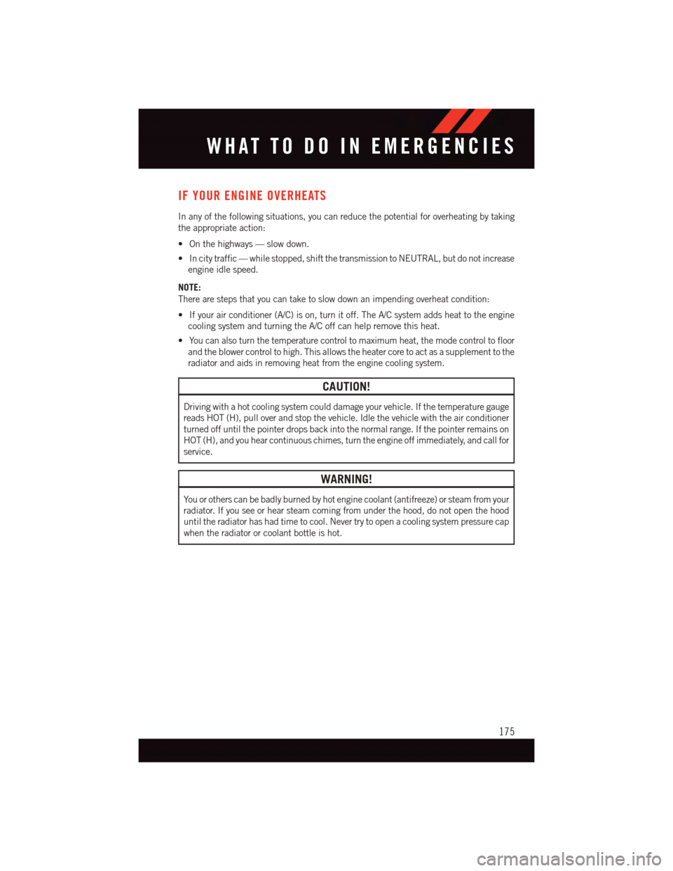
IF YOUR ENGINE OVERHEATS
In any of the following situations, you can reduce the potential for overheating by taking
the appropriate action:
•Onthehighways—slowdown.
•Incitytraffic—whilestopped,shiftthetransmissiontoNEUTRAL,butdonotincrease
engine idle speed.
NOTE:
There are steps that you can take to slow down an impending overheat condition:
•Ifyourairconditioner(A/C)ison,turnitoff.TheA/Csystemaddsheattotheengine
cooling system and turning the A/C off can help remove this heat.
•Youcanalsoturnthetemperaturecontroltomaximumheat,themodecontroltofloor
and the blower control to high. This allows the heater core to act as a supplement to the
radiator and aids in removing heat from the engine cooling system.
CAUTION!
Driving with a hot cooling system could damage your vehicle. If the temperature gauge
reads HOT (H), pull over and stop the vehicle. Idle the vehicle with the air conditioner
turned off until the pointer drops back into the normal range. If the pointer remains on
HOT (H), and you hear continuous chimes, turn the engine off immediately, and call for
service.
WARNING!
Yo u o r o t h e r s c a n b e b a d l y b u r n e d b y h o t e n g i n e c o o l a n t ( a n t i f r e e z e ) o r s t e a m f r o m y o u r
radiator. If you see or hear steam coming from under the hood, do not open the hood
until the radiator has had time to cool. Never try to open a cooling system pressure cap
when the radiator or coolant bottle is hot.
WHAT TO DO IN EMERGENCIES
175
Page 194 of 236
EVENT DATA RECORDER (EDR)
This vehicle is equipped with an Event Data Recorder (EDR). The main purpose of an EDR
is to record, in certain crash or near crash-like situations, such as an air bag deployment
or hitting a road obstacle, data that will assist in understanding how a vehicle’s systems
performed. The EDR is designed to record data related to vehicle dynamics and safety
systems for a short period of time, typically 30 seconds or less. The EDR in this vehicle is
designed to record such data as:
•Howvarioussystemsinyourvehiclewereoperating.
•Whetherornotthedriverandpassengersafetybeltswerebuckled/fastened.
•Howfar(ifatall)thedriverwasdepressingtheacceleratorand/orbrakepedal.
•Howfastthevehiclewastraveling.
These data can help provide a better understanding of the circumstances in which crashes
and injuries occur.
NOTE:
EDR data is recorded by your vehicle only if a non-trivial crash situation occurs; no data is
recorded by the EDR under normal driving conditions and no personal data (e.g. name,
gender, age, and crash location) is recorded. However, other parties, such as law
enforcement, could combine the EDR data with the type of personally identifying data
routinely acquired during a crash investigation.
To r e a d d a t a r e c o r d e d b y a n E D R , s p e c i a l e q u i p m e n t i s r e q u i r e d , a n d a c c e s s t o t h e v e h i c l e
or the EDR is needed. In addition to the vehicle manufacturer, other parties such as law
enforcement, that have the special equipment, can read the information if they have
access to the vehicle or the EDR.
CAP-LESS FUEL FILL FUNNEL
The funnel for the Cap-Less Fuel System is located on the jacking tool kit. If your vehicle
is out of fuel and an auxiliary fuel can is needed, insert the funnel into the filler neck and
proceed to fill the vehicle.
WHAT TO DO IN EMERGENCIES
192
Page 204 of 236
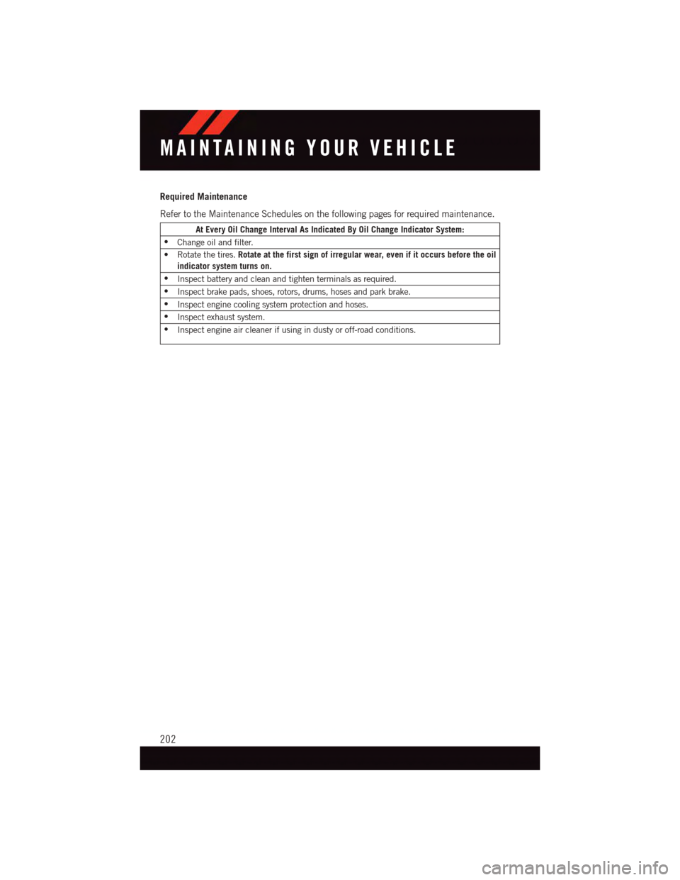
Required Maintenance
Refer to the Maintenance Schedules on the following pages for required maintenance.
At Every Oil Change Interval As Indicated By Oil Change Indicator System:
•Change oil and filter.
•Rotatethetires.Rotate at the first sign of irregular wear, even if it occurs before the oil
indicator system turns on.
•Inspect battery and clean and tighten terminals as required.
•Inspect brake pads, shoes, rotors, drums, hoses and park brake.
•Inspect engine cooling system protection and hoses.
•Inspect exhaust system.
•Inspect engine air cleaner if using in dusty or off-road conditions.
MAINTAINING YOUR VEHICLE
202
Page 205 of 236
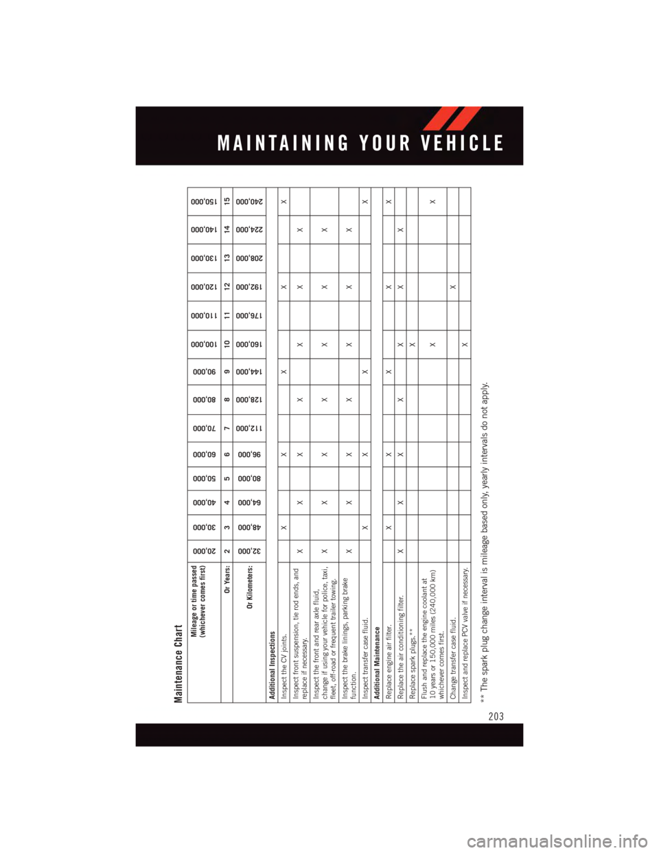
Maintenance Chart
Mileage or time passed(whichever comes first)
20,000
30,000
40,000
50,000
60,000
70,000
80,000
90,000
100,000
110,000
120,000
130,000
140,000
150,000
Or Years: 2 3 4 5 6 7 8 9 10 11 12 13 14 15
Or Kilometers:
32,000
48,000
64,000
80,000
96,000
112,000
128,000
144,000
160,000
176,000
192,000
208,000
224,000
240,000
Additional InspectionsInspect the CV joints. X X X X XInspect front suspension, tie rod ends, andreplace if necessary.
XXX X X X X
Inspect the front and rear axle fluid,change if using your vehicle for police, taxi,fleet, off-road or frequent trailer towing.
XXX X X X X
Inspect the brake linings, parking brakefunction.
XXX X X X X
Inspect transfer case fluid. X X X XAdditional MaintenanceReplace engine air filter. X X X X XReplace the air conditioning filter. X X X X X X XReplace spark plugs.**
X
Flush and replace the engine coolant at10 years or 150,000 miles (240,000 km)whichever comes first.
XX
Change transfer case fluid.
X
Inspect and replace PCV valve if necessary. X** The spark plug change interval is mileage based only, yearly intervals do not apply.
MAINTAINING YOUR VEHICLE
203
Page 209 of 236
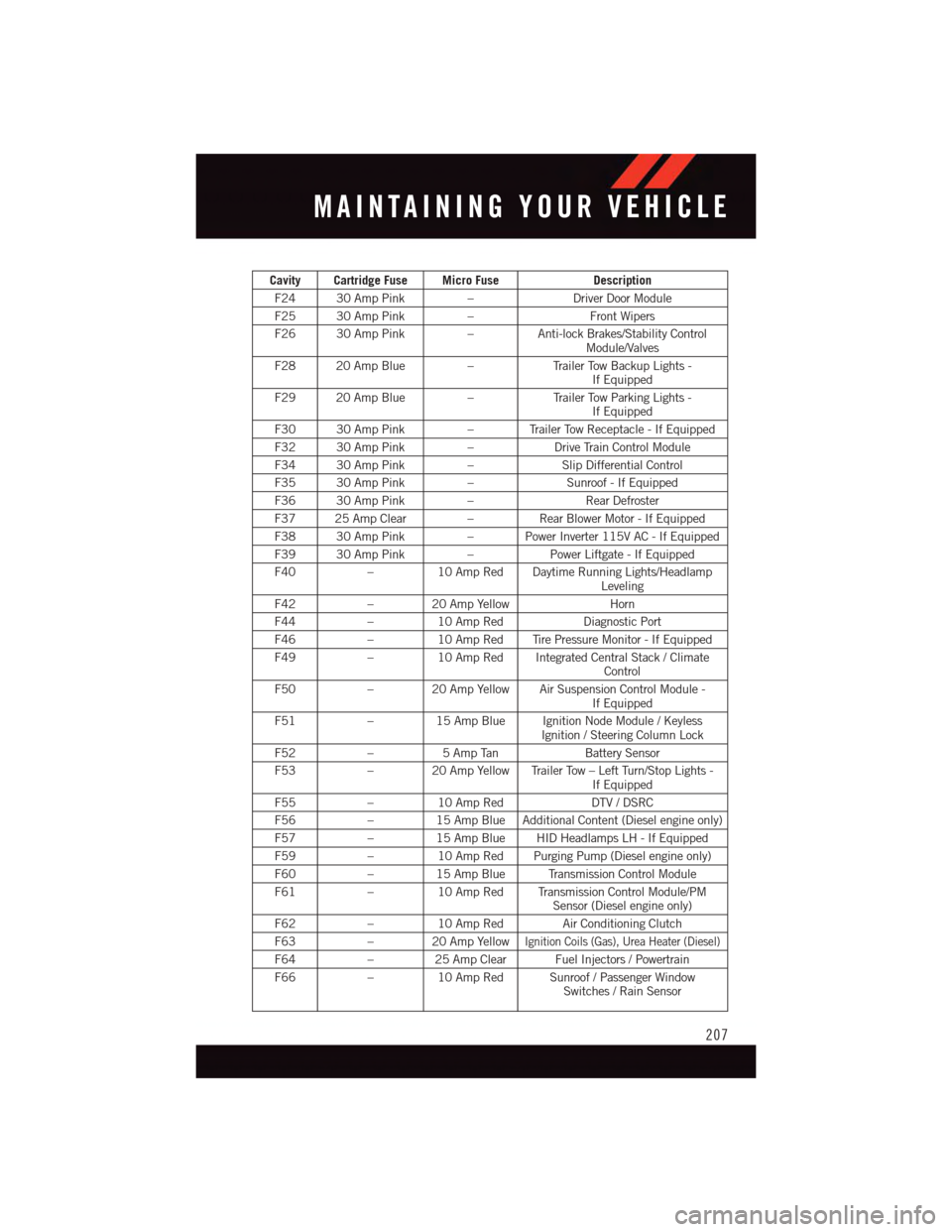
Cavity Cartridge Fuse Micro FuseDescription
F24 30 Amp Pink–Driver Door Module
F25 30 Amp Pink–Front Wipers
F26 30 Amp Pink–Anti-lock Brakes/Stability ControlModule/Valves
F28 20 Amp Blue–Tr a i l e r To w B a c k u p L i g h t s -If Equipped
F29 20 Amp Blue–Tr a i l e r To w P a r k i n g L i g h t s -If Equipped
F30 30 Amp Pink–TrailerTowReceptacle-IfEquipped
F32 30 Amp Pink–Drive Train Control Module
F34 30 Amp Pink–Slip Differential Control
F35 30 Amp Pink–Sunroof - If Equipped
F36 30 Amp Pink–Rear Defroster
F37 25 Amp Clear –Rear Blower Motor - If Equipped
F38 30 Amp Pink–PowerInverter115VAC-IfEquipped
F39 30 Amp Pink–Power Liftgate - If Equipped
F40–10 Amp Red Daytime Running Lights/HeadlampLeveling
F42–20AmpYellowHorn
F44–10 Amp RedDiagnostic Port
F46–10 Amp Red Tire Pressure Monitor - If Equipped
F49–10 Amp Red Integrated Central Stack / ClimateControl
F50–20AmpYellowAirSuspensionControlModule-If Equipped
F51–15 Amp Blue Ignition Node Module / KeylessIgnition / Steering Column Lock
F52–5AmpTanBattery Sensor
F53–20AmpYellowTrailerTow–LeftTurn/StopLights-If Equipped
F55–10 Amp RedDTV / DSRC
F56–15 Amp Blue Additional Content (Diesel engine only)
F57–15 Amp Blue HID Headlamps LH - If Equipped
F59–10 Amp Red Purging Pump (Diesel engine only)
F60–15 Amp Blue Transmission Control Module
F61–10 Amp Red Transmission Control Module/PMSensor (Diesel engine only)
F62–10 Amp Red Air Conditioning Clutch
F63–20AmpYellowIgnition Coils (Gas), Urea Heater (Diesel)
F64–25AmpClearFuelInjectors/Powertrain
F66–10 Amp Red Sunroof / Passenger WindowSwitches / Rain Sensor
MAINTAINING YOUR VEHICLE
207
Page 222 of 236
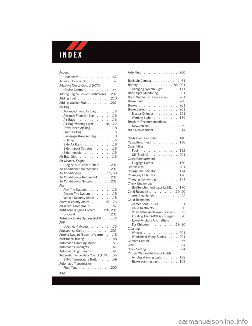
Access
Uconnect®..............67
Access, Uconnect®...........67
Adaptive Cruise Control (ACC)
(Cruise Control) . . . . . . . . . . . .44
Adding Engine Coolant (Antifreeze)..201
Adding Fuel..............210
Adding Washer Fluid..........201
Air Bag
Advanced Front Air Bag.......16
Advance Front Air Bag.......16Air Bags . . . . . . . . . . . . . . .16Air Bag Warning Light . . . . .16, 172Driver Knee Air Bag.........18Front Air Bag . . . . . . . . . . . .16Passenger Knee Air Bag.......18Rollover . . . . . . . . . . . . . . .16Side Air Bags............18Side Impact Curtains........18Side Impacts.............16Air Bag, Side . . . . . . . . . . . . . . .16Air Cleaner, Engine(Engine Air Cleaner Filter).....201Air Conditioner Maintenance.....201Air Conditioning...........55,58Air Conditioning Refrigerant......201Air Conditioning System........201AlarmArm The System...........15Disarm The System.........15Vehicle Security Alarm.......15Alarm (Security Alarm)......15,173All Wheel Drive (AWD).........157Antifreeze (Engine Coolant) . . .198, 201Disposal . . . . . . . . . . . . . .201Anti-Lock Brake System (ABS)....172APPUconnect®Access..........70Appearance Care............201Arming System (Security Alarm)....15Assistance Towing...........168Automatic Dimming Mirror.......51Automatic Headlights..........41Automatic High Beams.........41Automatic Temperature Control (ATC)...55SYNC Temperature Button.....59Automatic TransmissionFluid Type . . . . . . . . . . . . .200
Axle Fluid . . . . . . . . . . . . . . . .200
Back-Up Camera............61Battery . . . . . . . . . . . . . .186, 201Charging System Light......171Blind Spot Monitoring..........61Body Mechanism Lubrication.....201Brake Fluid . . . . . . . . . . . . . . .200Brakes.................201Brake System.............201Master Cylinder..........201Warning Light . . . . . . . . . . .169Break-In Recommendations,New Vehicle . . . . . . . . . . . . .39Bulb Replacement...........214
Calibration, Compass.........148Capacities, Fluid............198Caps, FillerFuel................192Oil (Engine)............201Cargo CompartmentLuggage Carrier..........160Car Washes . . . . . . . . . . . . . . .201Change Oil Indicator..........174Changing A Flat Tire..........176Charging System Light.........171Check Engine Light(Malfunction Indicator Light). . . .170Child Restraint...........19,20Arm Rest Tether . . . . . . . . . . .22Child RestraintsCenter Seat LATCH.........21Child Restraints...........20Child Tether Anchorage Locations...22Locating The LATCH Anchorages...20Lower Anchors And TethersFor Children . . . . . . . . . .19, 20CleaningWheels...............201Windshield Wiper Blades.....201Climate Control . . . . . . . . . . . . .55Clock . . . . . . . . . . . . . . . . . . .84Clock Setting...............84Cluster Warning/Indicator LightsAir Bag Warning Light . . . . . . .172Brake Warning Light . . . . . . . .169
INDEX
220