DODGE DURANGO 2017 3.G Owners Manual
Manufacturer: DODGE, Model Year: 2017, Model line: DURANGO, Model: DODGE DURANGO 2017 3.GPages: 584, PDF Size: 5.14 MB
Page 581 of 584

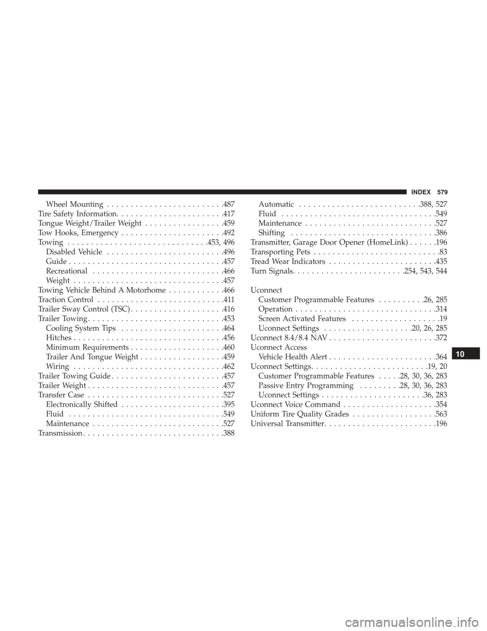
Wheel Mounting........................ .487
Tire Safety Information ...................... .417
Tongue Weight/Trailer Weight .................459
Tow Hooks, Emergency ..................... .492
Towing ............................. .453, 496
Disabled Vehicle ........................ .496
Guide ................................ .457
Recreational ........................... .466
Weight ............................... .457
Towing Vehicle Behind A Motorhome ............466
Traction Control ...........................411
Trailer Sway Control (TSC) ....................416
Trailer Towing ............................ .453
Cooling System Tips ..................... .464
Hitches ............................... .456
Minimum Requirements ....................460
Trailer And Tongue Weight ..................459
Wiring ............................... .462
Trailer Towing Guide ....................... .457
Trailer Weight ............................ .457
Transfer Case ............................ .527
Electronically Shifted ..................... .395
Fluid ................................ .549
Maintenance ........................... .527
Transmission ............................. .388Automatic
......................... .388, 527
Fluid ................................ .549
Maintenance ........................... .527
Shifting .............................. .386
Transmitter, Garage Door Opener (HomeLink) ......196
Transporting Pets ...........................83
Tread Wear Indicators ...................... .435
Turn Signals ....................... .254, 543, 544
Uconnect Customer Programmable Features ..........26, 285
Operation ............................. .314
Scr
een Activated Features ...................19
Uconnect Settings ...................20, 26, 285
Uconnect 8.4/8.4 NAV ...................... .372
Uconnect Access Vehicle Health Alert ...................... .364
Uconnect Settings ........................ .19, 20
Customer Programmable Features .....28, 30, 36, 283
Passive Entry Programming .........28, 30, 36, 283
Uconnect Settings ..................... .36, 283
Uconnect Voice Command ....................354
Uniform Tire Quality Grades ..................563
Universal Transmitter ....................... .196
10
INDEX 579
Page 582 of 584

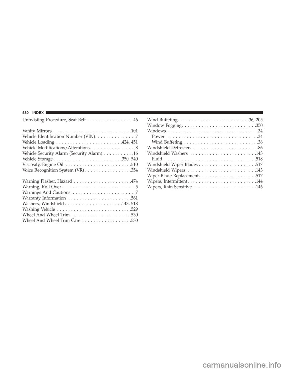
Untwisting Procedure, Seat Belt.................46
Vanity Mirrors ............................ .101
Vehicle Identification Number (VIN) ...............7
Vehicle Loading ....................... .424, 451
Vehicle Modifications/Alterations .................8
Vehicle Security Alarm (Security Alarm) ...........16
Vehicle Storage ........................ .350, 540
Viscosity, Engine Oil ....................... .510
Voice Recognition System (VR) .................354
Warning Flasher, Hazard .....................474
Warning, Roll Over ...........................5
Warnings And Cautions .......................7
Warranty Information ...................... .561
Washers, Windshield .....................143, 518
Washing Vehicle .......................... .529
Wheel And Wheel Trim ..................... .530
Wheel And Wheel Trim Care ..................530 Wind Buffeting
......................... .36, 205
Window Fogging .......................... .350
Windows .................................34
Power .................................34
Wind Buffeting ...........................36
Windshield Defroster .........................86
Windshield Washers ....................... .143
Fluid ................................ .518
Windshield Wiper Blades .....................517
Windshield Wipers ........................ .143
Wiper Blade Replacement .....................517
Wipers, Intermittent ........................ .144
Wipers, Rain Sensitive ...................... .146
580 INDEX
Page 583 of 584

INSTALLATION OF RADIO TRANSMITTING
EQUIPMENT
Special design considerations are incorporated into this
vehicle’s electronic system to provide immunity to radio
frequency signals. Mobile two-way radios and telephone
equipment must be installed properly by trained person-
nel. The following must be observed during installation.
The positive power connection should be made directly
to the battery and fused as close to the battery as possible.
The negative power connection should be made to body
sheet metal adjacent to the negative battery connection.
This connection should not be fused.
Antennas for two-way radios should be mounted on the
roof or the rear area of the vehicle. Care should be used
in mounting antennas with magnet bases. Magnets may
affect the accuracy or operation of the compass on
vehicles so equipped.The antenna cable should be as short as practical and
routed away from the vehicle wiring when possible. Use
only fully shielded coaxial cable.
Carefully match the antenna and cable to the radio to
ensure a low Standing Wave Ratio (SWR).
Mobile radio equipment with output power greater than
normal may require special precautions.
All installations should be checked for possible interfer-
ence between the communications equipment and the
vehicle’s electronic systems.
Page 584 of 584

First Edition
Printed in U.S.A.
17WD01-126-AA
©2016 FCA US LLC. All Rights Reserved.
Dodge is a registered trademark of FCA US LLC.
STICK WITH THE SPECIALISTS®