door DODGE DURANGO 2019 Service Manual
[x] Cancel search | Manufacturer: DODGE, Model Year: 2019, Model line: DURANGO, Model: DODGE DURANGO 2019Pages: 598, PDF Size: 4.32 MB
Page 121 of 598
3. Push and hold the Homelink button you want toprogram while you push and hold the hand-held trans-
mitter button.
4. Continue to hold both buttons and observe the indicator light. The Homelink indicator will flash slowly and then
rapidly after HomeLink has received the frequency
signal from the hand-held transmitter. Release both
buttons after the indicator light changes from slow to
rapid.
5. Push and hold the programmed HomeLink button and observe the indicator light.
• If the indicator light stays on constantly, programming
is complete and the garage door/device should acti-
vate when the HomeLink button is pushed.
• To program the two remaining HomeLink buttons,
repeat each step for each remaining button. DO NOT
erase the channels.
Canadian/Gate Operator Programming
For programming transmitters in Canada/United States
that require the transmitter signals to “time-out” after
several seconds of transmission: Canadian radio frequency laws require transmitter signals
to time-out (or quit) after several seconds of transmission,
which may not be long enough for HomeLink to pick up
the signal during programming. Similar to this Canadian
law, some U.S. gate operators are designed to time-out in
the same manner.
It may be helpful to unplug the device during the cycling
process to prevent possible overheating of the garage door
or gate motor.
1. Cycle the ignition to the ON/RUN position.
NOTE:
For vehicles equipped with Keyless Enter-N-Go,
place the ignition in the RUN position with the engine ON.
Make sure while programming HomeLink with the engine
ON that your vehicle is outside of your garage, or that the
garage door remains open at all times.
2. Place the hand-held transmitter 1 to 3 inches (3 to 8 cm) away from the HomeLink button you wish to program
while keeping the HomeLink indicator light in view.
3. Continue to push and hold the HomeLink button while you push and release (“cycle”) your hand-held trans-
mitter every two seconds until HomeLink has success-
fully accepted the frequency signal. The indicator light
will flash slowly and then rapidly when fully trained.
3
GETTING TO KNOW YOUR VEHICLE 119
Page 122 of 598
4. Watch for the HomeLink indicator to change flash rates.When it changes, it is programmed. It may take up to 30
seconds or longer in rare cases. The garage door may
open and close while you are programming.
5. Push and hold the programmed HomeLink button and observe the indicator light.
NOTE: •If the indicator light stays on constantly, programming
is complete and the garage door/device should acti-
vate when the HomeLink button is pushed.
• To program the two remaining HomeLink buttons,
repeat each step for each remaining button. DO NOT
erase the channels.
If you unplugged the garage door opener/device for
programming, plug it back in at this time.
Using HomeLink
To operate, switch the ignition to the ON/RUN position
and the press and release the programmed HomeLink
button. Activation will now occur for the programmed
device (i.e., garage door opener, gate operator, security
system, entry door lock, home/office lighting, etc.,). The
hand-held transmitter of the device may also be used at any time. If the ignition is switched to the OFF position,
HomeLink will remain active for three minutes. During
this time, if the vehicle is locked, HomeLink is disabled.
Security
It is advised to erase all channels before you sell or turn in
your vehicle.
To do this, push and hold the two outside buttons for 20
seconds until the red indicator flashes.
NOTE:
All channels will be erased. Individual channels
cannot be erased.
The HomeLink Universal Transceiver is disabled when the
Vehicle Security Alarm is active.
Troubleshooting Tips
If you are having trouble programming HomeLink, here
are some of the most common solutions:
• Replace the battery in the Garage Door Opener hand-
held transmitter.
• Push the LEARN button on the Garage Door Opener to
complete the training for a Rolling Code.
• Did you unplug the device for programming and re-
member to plug it back in?
120 GETTING TO KNOW YOUR VEHICLE
Page 123 of 598
If you have any problems, or require assistance, please call
toll-free 1-800-355-3515 or, on the Internet at
HomeLink.com for information or assistance.
WARNING!
•Vehicle exhaust contains carbon monoxide, a danger-
ous gas. Do not run your vehicle in the garage while
programming the transceiver. Exhaust gas can cause
serious injury or death.
• Your motorized door or gate will open and close
while you are programming the universal trans-
ceiver. Do not program the transceiver if people, pets
or other objects are in the path of the door or gate.
Only use this transceiver with a garage door opener
that has a “stop and reverse” feature as required by
Federal safety standards. This includes most garage
door opener models manufactured after 1982. Do not
use a garage door opener without these safety fea-
tures. Call toll-free 1-800-355-3515 or, on the Internet
at HomeLink.com for safety information or assis-
tance.
General Information
The following regulatory statement applies to all Radio
Frequency (RF) devices equipped in this vehicle:
This device complies with Part 15 of the FCC Rules and
with Innovation, Science and Economic Development
Canada license-exempt RSS standard(s). Operation is sub-
ject to the following two conditions:
1. This device may not cause harmful interference, and
2. This device must accept any interference received, in-
cluding interference that may cause undesired opera-
tion.
NOTE: Changes or modifications not expressly approved
by the party responsible for compliance could void the
user ’s authority to operate the equipment.
3
GETTING TO KNOW YOUR VEHICLE 121
Page 124 of 598
INTERNAL EQUIPMENT
Storage
Glove Compartment
The glove compartment is located on the passenger side of
the instrument panel.
To open the glove compartment, pull the release handle.
Door Storage
Large storage areas are built into the door panels for easy
access.
Glove Compartment
Door Panel Storage
122 GETTING TO KNOW YOUR VEHICLE
Page 137 of 598
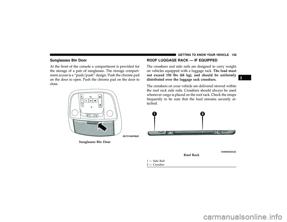
Sunglasses Bin Door
At the front of the console a compartment is provided for
the storage of a pair of sunglasses. The storage compart-
ment access is a “push/push” design. Push the chrome pad
on the door to open. Push the chrome pad on the door to
close.
ROOF LUGGAGE RACK — IF EQUIPPED
The crossbars and side rails are designed to carry weight
on vehicles equipped with a luggage rack.The load must
not exceed 150 lbs (68 kg), and should be uniformly
distributed over the luggage rack crossbars.
The crossbars on your vehicle are delivered stowed within
the roof rack side rails. Crossbars should always be used
whenever cargo is placed on the roof rack. Check the straps
frequently to be sure that the load remains securely at-
tached.
Sunglasses Bin Door
Roof Rack
1 — Side Rail
2 — Crossbar
3
GETTING TO KNOW YOUR VEHICLE 135
Page 148 of 598
4. Fuel Gauge•The pointer shows the level of fuel in the fuel tank
when the Keyless Push Button Ignition is in the
ON/RUN position.
•
The fuel pump symbol points to the side of the
vehicle where the fuel door is located.
5. Instrument Cluster Display
•The instrument cluster display features a driver-
interactive display. Refer to “Instrument Cluster Dis-
play” in “Getting To Know Your Instrument Panel” for
further information.
NOTE: The hard telltales will illuminate for a bulb check
when the ignition is first cycled.
INSTRUMENT CLUSTER DISPLAY
Your vehicle will be equipped with an instrument cluster
display, which offers useful information to the driver. With
the ignition in the STOP/OFF mode, opening/closing of a
door will activate the display for viewing, and display the
total miles, or kilometers, in the odometer. Your instrument
cluster display is designed to display important informa-
tion about your vehicle’s systems and features. Using a driver interactive display located on the instrument panel,
your instrument cluster display can show you how sys-
tems are working and give you warnings when they are
not. The steering wheel mounted controls allow you to
scroll through the main menus and submenus. You can
access the specific information you want and make selec-
tions and adjustments.
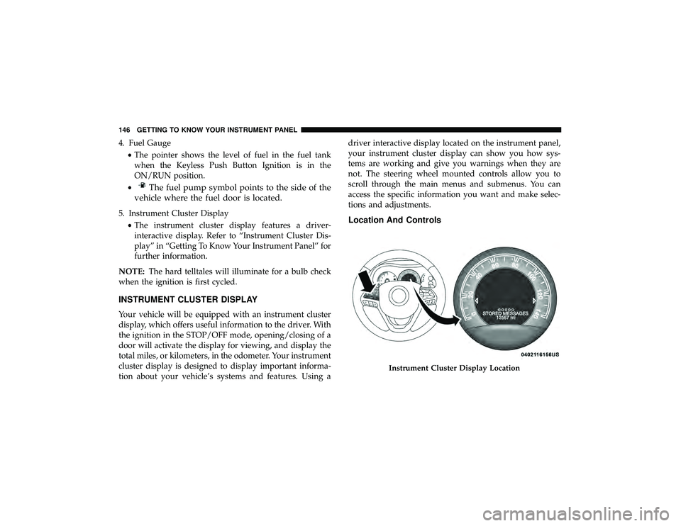
Location And Controls
Instrument Cluster Display Location
146 GETTING TO KNOW YOUR INSTRUMENT PANEL
Page 151 of 598
•Unstored Messages
This message type is displayed indefinitely or until the
condition that activated the message is cleared. Examples
of this message type are “Turn Signal On” (if a turn signal
is left on) and “Lights On” (if driver leaves the vehicle).
• Unstored Messages Until RUN
These messages deal primarily with the Remote Start
feature. This message type is displayed until the ignition is
in the RUN state. Examples of this message type are
“Remote Start Canceled - Door Ajar” and “Press Brake
Pedal and Push Button to Start.”
• Five Second Unstored Messages
When the appropriate conditions occur, this type of mes-
sage takes control of the main display area for five seconds
and then returns to the previous screen. An example of this
message type is “Automatic High Beams On.”
Engine Oil Life Reset
Oil Change Required
Your vehicle is equipped with an engine oil change indi-
cator system. The “Oil Change Required” message will
display in the instrument cluster display for five seconds after a single chime has sounded, to indicate the next
scheduled oil change interval. The engine oil change indi-
cator system is duty cycle based, which means the engine
oil change interval may fluctuate, dependent upon your
personal driving style.
Unless reset, this message will continue to display each
time you place the ignition in the ON/RUN position. To
turn off the message temporarily, push and release the
OK
or arrow buttons. To reset the oil change indicator system
(after performing the scheduled maintenance), refer to the
following procedure.
Vehicles Equipped With Keyless Enter-N-Go — Ignition
Use the steering wheel instrument cluster display controls
for the following procedure(s):
1. Without pressing the brake pedal, push the ENGINE START/STOP button and place the ignition in the
ON/RUN position (do not start the engine).
2. Push and release the downarrow button to scroll
downward through the main menu to “Vehicle Info.”
3. Push and release the rightarrow button to access the
”Oil Life” screen.
4
GETTING TO KNOW YOUR INSTRUMENT PANEL 149
Page 153 of 598
•Cruise Set To XXX MPH or km/h
• Tire Pressure Screen With Low Tire(s)
• Service Tire Pressure System
• Park Brake Engaged
• Brake Fluid Low
• Engine Temperature Hot
• Lights On
• Right Front Turn Signal Light Out
• Right Rear Turn Signal Light Out
• Left Front Turn Signal Light Out
• Left Rear Turn Signal Light Out
• Ignition or Accessory On
• Vehicle Not In Park
• Remote Start Active Push Start Button
• Remote Start Canceled Fuel Low
• Remote Start Canceled Too Cold
• Remote Start Canceled Door Open
• Remote Start Canceled Hood Open •
Remote Start Canceled Liftgate Open
• Remote Start Canceled Time Expired
• Remote Start Disabled Start To Reset
• Service Air Bag System
• Service Air Bag Warning Light
• Door Open
• Doors Open
• Liftgate Open
• Hood Open
• Shift Not Allowed
• Vehicle Speed Too High To Shift to D
• Vehicle Speed is Too High to Shift to R
• Vehicle Speed is Too High to Shift to P
• Service Transmission
• Service Shifter
The Reconfigurable Telltales section is divided into the
white or yellow telltales area on the left, and the green or
red telltales area on the right.
4
GETTING TO KNOW YOUR INSTRUMENT PANEL 151
Page 162 of 598
WARNING!
Driving a vehicle with the red brake light on is
dangerous. Part of the brake system may have failed. It
will take longer to stop the vehicle. You could have a
collision. Have the vehicle checked immediately.
Vehicles equipped with the Anti-Lock Brake System (ABS)
are also equipped with Electronic Brake Force Distribution
(EBD). In the event of an EBD failure, the Brake Warning
Light will turn on along with the ABS Light. Immediate
repair to the ABS system is required.
Operation of the Brake Warning Light can be checked by
turning the ignition switch from the OFF position to the
ON/RUN position. The light should illuminate for ap-
proximately two seconds. The light should then turn off
unless the parking brake is applied or a brake fault is
detected. If the light does not illuminate, have the light
inspected by an authorized dealer.
The light also will turn on when the parking brake is
applied with the ignition switch in the ON/RUN position. NOTE:
This light shows only that the parking brake is
applied. It does not show the degree of brake application.— Battery Charge Warning Light
This warning light will illuminate when the battery is not
charging properly. If it stays on while the engine is run-
ning, there may be a malfunction with the charging system.
Contact an authorized dealer as soon as possible.
This indicates a possible problem with the electrical system
or a related component.
— Door Open Warning Light — If Equipped
This indicator will illuminate when a door is ajar/open and
not fully closed.
NOTE: If the vehicle is moving, there will also be a single
chime.
— Electric Power Steering Fault Warning Light
This warning light will turn on when there’s a fault with
the EPS (Electric Power Steering) system. Refer to “Power
Steering” in “Starting And Operating” for further informa-
tion.
160 GETTING TO KNOW YOUR INSTRUMENT PANEL
Page 179 of 598
The following conditions must be met in order for HSA to
activate:
•The feature must be enabled.
• The vehicle must be stopped.
• Park brake must be off.
• Driver door must be closed.
• The vehicle must be on a sufficient grade.
• The gear selection must match vehicle uphill direction
(i.e., vehicle facing uphill is in forward gear; vehicle
backing uphill is in REVERSE gear).
• HSA will work in REVERSE gear and all forward gears.
The system will not activate if the transmission is in
PARK or NEUTRAL. For vehicles equipped with a
manual transmission, if the clutch is pressed, HSA will
remain active.
WARNING!
There may be situations where the Hill Start Assist
(HSA) will not activate and slight rolling may occur,
such as on minor hills or with a loaded vehicle, or
(Continued)
WARNING! (Continued)
while pulling a trailer. HSA is not a substitute for
active driving involvement. It is always the driver ’s
responsibility to be attentive to distance to other ve-
hicles, people, and objects, and most importantly brake
operation to ensure safe operation of the vehicle under
all road conditions. Your complete attention is always
required while driving to maintain safe control of your
vehicle. Failure to follow these warnings can result in
a collision or serious personal injury.
Disabling And Enabling HSA
This feature can be turned on or turned off. To change the
current setting, proceed as follows:
•If disabling HSA using your instrument cluster display,
refer to “Instrument Cluster Display” in “Getting To
Know Your Instrument Panel” for further information.
• If disabling HSA using Uconnect Settings, refer to
“Uconnect Settings” in “Multimedia” for further infor-
mation.
5
SAFETY 177