warning lights DODGE DURANGO 2020 User Guide
[x] Cancel search | Manufacturer: DODGE, Model Year: 2020, Model line: DURANGO, Model: DODGE DURANGO 2020Pages: 464, PDF Size: 22.14 MB
Page 120 of 464
118GETTING TO KNOW YOUR INSTRUMENT PANEL
LaneSense Indicator Light — If Equipped
The LaneSense indicator light
illuminates solid green when both
lane markings have been detected
and the system is “armed” and ready
to provide visual and torque warnings if an
unintentional lane departure occurs. Refer to
“LaneSense — If Equipped” in “Starting And
Operating” for further information.
Park/Headlight On Indicator Light
This indicator light will illuminate
when the park lights or headlights are
turned on. Refer to “Exterior Lights” in
“Getting To Know Your Vehicle” for
further information.
Snow Mode SRT Indicator Light
This light will turn on when Snow
Mode is active. Refer to the Drive
Modes Supplement for further
information.
Stop/Start Active Indicator Light — If
Equipped
This indicator light will illuminate
when the Stop/Start function is in
“Autostop” mode. Refer to “Stop /
Start System — If Equipped” in
“Starting And Operating” for further
information.
Sport Mode Indicator Light
This light will turn on when Sport
Mode is active. Refer to “Sport Mode
— If Equipped” in “Starting And
Operating” for further information.
Sport Mode SRT Indicator Light
This light will turn on when Sport
Mode is active. Refer to the Drive
Modes Supplement for further
information.
Tow Mode SRT Indicator Light
This light will turn on when Tow Mode
is active. Refer to the Drive Modes
Supplement for further information.
Track Mode SRT Indicator Light
This light will turn on when Track
Mode is active. Refer to the Drive
Modes Supplement for further
information.
Turn Signal Indicator Lights
When the left or right turn signal is
activated, the turn signal indicator will
flash independently and the
corresponding exterior turn signal
lamps will flash. Turn signals can be activated
when the multifunction lever is moved down
(left) or up (right).
NOTE:
A continuous chime will sound if the vehicle is
driven more than 1 mile (1.6 km) with either
turn signal on.
Check for an inoperative outside light bulb if
either indicator flashes at a rapid rate.
20_WD_OM_EN_USC_t.book Page 118
Page 121 of 464
GETTING TO KNOW YOUR INSTRUMENT PANEL119
WHITE INDICATOR LIGHTS
Adaptive Cruise Control (ACC) Ready Light
— If Equipped
This light will turn on when Adaptive
Cruise Control (ACC) has been turned
on, but is not set. Refer to “Adaptive
Cruise Control (ACC)” in “Starting And
Operating” for further information.
Custom Mode SRT Indicator Light
This light will turn on when Custom
Mode SRT is active. Refer to the Drive
Modes Supplement for further
information.
Cruise Control Ready Indicator
This indicator light will illuminate
when the cruise control is ready, but
not set. Refer to “Speed Control” in
“Starting And Operating” for further
information.
SRT Speed Warning Indicator Light — If
Equipped
When Set Speed Warning is turned
on, the speed warning telltale will
illuminate in the instrument cluster
with a number matching the set
speed. When the set speed is exceeded, the
indication will light up yellow and flash along
with a continuous chime. Speed Warning can be
turned on and off in the instrument cluster
display.
Refer to “Instrument Cluster Display” in this
chapter for further information.
The number “55” is only an example of a speed
that can be set.
LaneSense Indicator Light — If Equipped
When the LaneSense system is ON,
but not armed, the LaneSense
indicator light illuminates solid white.
This occurs when only left, right, or
neither lane line has been detected. If a single
lane line is detected, the system is ready to
provide only visual warnings if an unintentional
lane departure occurs on the detected lane line. Refer to “LaneSense — If Equipped” in “Starting
And Operating” for further information.
Valet Mode SRT Indicator Light
This light will turn on when Valet Mode
is active. Refer to the Drive Modes
Supplement for further information.
BLUE INDICATOR LIGHTS
High Beam Indicator Light
This indicator light will illuminate to
indicate that the high beam
headlights are on. With the low beams
activated, push the multifunction
lever forward (toward the front of the vehicle) to
turn on the high beams. Pull the multifunction
lever rearward (toward the rear of the vehicle) to
turn off the high beams. If the high beams are
off, pull the lever toward you for a temporary
high beam on, “flash to pass” scenario.
3
20_WD_OM_EN_USC_t.book Page 119
Page 136 of 464
134SAFETY
Rear Cross Path (RCP)
The Rear Cross Path (RCP) feature is intended
to aid the driver when backing out of parking
spaces where their vision of oncoming vehicles
may be blocked. Proceed slowly and cautiously
out of the parking space until the rear end of the
vehicle is exposed. The RCP system will then
have a clear view of the cross traffic and if an
oncoming vehicle is detected, alert the driver.
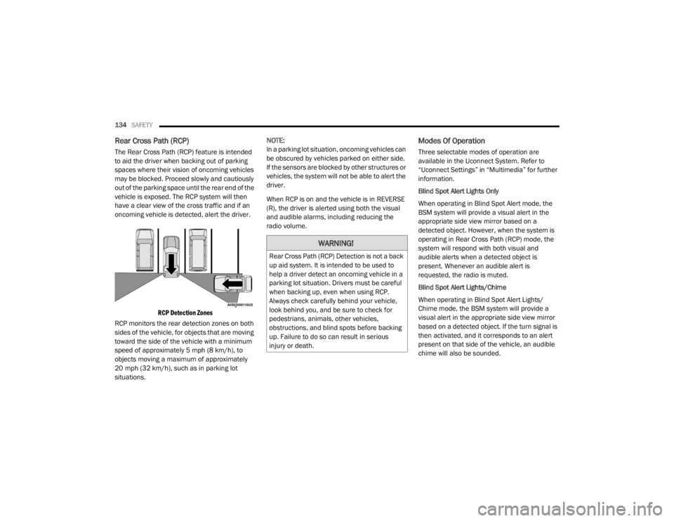
RCP Detection Zones
RCP monitors the rear detection zones on both
sides of the vehicle, for objects that are moving
toward the side of the vehicle with a minimum
speed of approximately 5 mph (8 km/h), to
objects moving a maximum of approximately
20 mph (32 km/h), such as in parking lot
situations. NOTE:
In a parking lot situation, oncoming vehicles can
be obscured by vehicles parked on either side.
If the sensors are blocked by other structures or
vehicles, the system will not be able to alert the
driver.
When RCP is on and the vehicle is in REVERSE
(R), the driver is alerted using both the visual
and audible alarms, including reducing the
radio volume.
Modes Of Operation
Three selectable modes of operation are
available in the Uconnect System. Refer to
“Uconnect Settings” in “Multimedia” for further
information.
Blind Spot Alert Lights Only
When operating in Blind Spot Alert mode, the
BSM system will provide a visual alert in the
appropriate side view mirror based on a
detected object. However, when the system is
operating in Rear Cross Path (RCP) mode, the
system will respond with both visual and
audible alerts when a detected object is
present. Whenever an audible alert is
requested, the radio is muted.
Blind Spot Alert Lights/Chime
When operating in Blind Spot Alert Lights/
Chime mode, the BSM system will provide a
visual alert in the appropriate side view mirror
based on a detected object. If the turn signal is
then activated, and it corresponds to an alert
present on that side of the vehicle, an audible
chime will also be sounded.
WARNING!
Rear Cross Path (RCP) Detection is not a back
up aid system. It is intended to be used to
help a driver detect an oncoming vehicle in a
parking lot situation. Drivers must be careful
when backing up, even when using RCP.
Always check carefully behind your vehicle,
look behind you, and be sure to check for
pedestrians, animals, other vehicles,
obstructions, and blind spots before backing
up. Failure to do so can result in serious
injury or death.
20_WD_OM_EN_USC_t.book Page 134
Page 158 of 464
156SAFETY
Front Air Bag Operation
Front Air Bags are designed to provide
additional protection by supplementing the seat
belts. Front air bags are not expected to reduce
the risk of injury in rear, side, or rollover
collisions. The front air bags will not deploy in all
frontal collisions, including some that may
produce substantial vehicle damage — for
example, some pole collisions, truck
underrides, and angle offset collisions.
On the other hand, depending on the type and
location of impact, front air bags may deploy in
crashes with little vehicle front-end damage but
that produce a severe initial deceleration.
Because air bag sensors measure vehicle
deceleration over time, vehicle speed and
damage by themselves are not good indicators
of whether or not an air bag should have
deployed.
Seat belts are necessary for your protection in
all collisions, and also are needed to help keep
you in position, away from an inflating air bag.
When the ORC detects a collision requiring the
front air bags, it signals the inflator units. A large
quantity of non-toxic gas is generated to inflate
the front air bags. The steering wheel hub trim cover and the
upper passenger side of the instrument panel
separate and fold out of the way as the air bags
inflate to their full size. The front air bags fully
inflate in less time than it takes to blink your
eyes. The front air bags then quickly deflate
while helping to restrain the driver and front
passenger.
Knee Impact Bolsters
The Knee Impact Bolsters help protect the
knees of the driver and front passenger, and
position the front occupants for improved
interaction with the front air bags.
WARNING!
No objects should be placed over or near
the air bag on the instrument panel or
steering wheel because any such objects
could cause harm if the vehicle is in a colli
-
sion severe enough to cause the air bag to
inflate.
Do not put anything on or around the air
bag covers or attempt to open them manu -
ally. You may damage the air bags and you
could be injured because the air bags may
no longer be functional. The protective
covers for the air bag cushions are
designed to open only when the air bags
are inflating.
Relying on the air bags alone could lead to
more severe injuries in a collision. The air
bags work with your seat belt to restrain you
properly. In some collisions, air bags won’t
deploy at all. Always wear your seat belts
even though you have air bags.
WARNING!
Do not drill, cut, or tamper with the knee
impact bolsters in any way.
Do not mount any accessories to the knee
impact bolsters such as alarm lights,
stereos, citizen band radios, etc.
20_WD_OM_EN_USC_t.book Page 156
Page 163 of 464
SAFETY161
(Continued)
Enhanced Accident Response System
In the event of an impact, if the communication
network remains intact, and the power remains
intact, depending on the nature of the event,
the Occupant Restraint Controller (ORC) will
determine whether to have the Enhanced
Accident Response System perform the
following functions:
Cut off fuel to the engine (if equipped)
Cut off battery power to the electric motor (if
equipped)
Flash hazard lights as long as the battery has
power
Turn on the interior lights, which remain on
as long as the battery has power or for
15 minutes from the intervention of the
Enhanced Accident Response System
Unlock the power door locks
Your vehicle may also be designed to perform
any of these other functions in response to the
Enhanced Accident Response System:
Turn off the Fuel Filter Heater, Turn off the
HVAC Blower Motor, Close the HVAC Circula -
tion Door
Cut off battery power to the:
Engine
Electric Motor (if equipped)
Electric power steering
Brake booster
Electric park brake
Automatic transmission gear selector
Horn
Front wiper
Headlamp washer pump
NOTE:
After an accident, remember to cycle the igni -
tion to the STOP (OFF/LOCK) position and
remove the key from the ignition switch to avoid
draining the battery. Carefully check the vehicle
for fuel leaks in the engine compartment and on
the ground near the engine compartment and
fuel tank before resetting the system and
starting the engine. If there are no fuel leaks or
damage to the vehicle electrical devices (e.g.
headlights) after an accident, reset the system
by following the procedure described below. If you have any doubt, contact an authorized
dealer.
Enhanced Accident Response System
Reset Procedure
In order to reset the Enhanced Accident
Response System functions after an event, the
ignition switch must be changed from ignition
START or ON/RUN to ignition OFF. Carefully
check the vehicle for fuel leaks in the engine
compartment and on the ground near the
engine compartment and fuel tank before
resetting the system and starting the engine.
Maintaining Your Air Bag System
WARNING!
Modifications to any part of the air bag
system could cause it to fail when you need
it. You could be injured if the air bag system
is not there to protect you. Do not modify
the components or wiring, including adding
any kind of badges or stickers to the
steering wheel hub trim cover or the upper
passenger side of the instrument panel. Do
not modify the front bumper, vehicle body
structure, or add aftermarket side steps or
running boards.
4
20_WD_OM_EN_USC_t.book Page 161
Page 185 of 464
SAFETY183
PERIODIC SAFETY CHECKS YOU SHOULD
M
AKE OUTSIDE THE VEHICLE
Tires
Examine tires for excessive tread wear and
uneven wear patterns. Check for stones, nails,
glass, or other objects lodged in the tread or
sidewall. Inspect the tread for cuts and cracks.
Inspect sidewalls for cuts, cracks, and bulges.
Check the wheel nuts for tightness. Check the
tires (including spare) for proper cold inflation
pressure.
Lights
Have someone observe the operation of brake
lights and exterior lights while you work the
controls. Check turn signal and high beam
indicator lights on the instrument panel.
Door Latches
Check for proper closing, latching, and locking.
Fluid Leaks
Check area under the vehicle after overnight
parking for fuel, coolant, oil, or other fluid leaks.
Also, if gasoline fumes are detected or if fuel, or
brake fluid leaks are suspected, the cause
should be located and corrected immediately.
WARNING!
To prevent SERIOUS INJURY or DEATH when
using “Track-Use” parts and equipment:
NEVER use any “Track-Use” equipment on
public roads. FCA US LLC does not autho -
rize the use of “Track-Use” equipment on
public roads.
The intended use of “Track-Use” parts is for
race vehicles on race tracks. To help
ensure the safety of the race driver, engi -
neers should supervise the installation of
“Track-Use” parts.
FCA US LLC does not authorize the installa -
tion or use of any part noted as “Track-Use”
on any new vehicle prior to its first retail
sale.
WARNING!
To prevent SERIOUS INJURY or DEATH:
ALWAYS remove any “Track-Use” equip -
ment before driving on public roads.
ALWAYS properly use your three-point seat
belts when driving on public roads.
In a collision, you and your passengers can
suffer much greater injuries if you are not
properly buckled up. You can strike the inte -
rior of your vehicle or other passengers, or
you can be thrown out of the vehicle.
4
20_WD_OM_EN_USC_t.book Page 183
Page 202 of 464
200STARTING AND OPERATING
The LOW RANGE position is designed for loose,
slippery road surfaces only. Driving in the LOW
RANGE position on dry hard surfaced roads may
cause increased tire wear and damage to the
driveline components.
Transfer Case Position Indicator Messages
The Transfer Case Position Indicator messages
(AWD AUTO and LOW RANGE) are located in the
instrument cluster and indicate the current and
desired transfer case selection. Refer to
“Instrument Cluster Display” in “Getting To
Know Your Instrument Panel” for further
information. When you select a different
transfer case position, the position indicator
lights will do the following:
If All Shift Conditions Are Met:
1. The current position indicator light will turn
off.
2. The selected position indicator light will flash until the transfer case completes the
shift.
3. When the shift is complete, the indicator light for the selected position will stop
flashing and remain on. If shift conditions are not met, one or more of
the following events may occur:
1. The indicator light for the current position
will remain on.
2. The newly selected position indicator light will continue to flash.
3. The transfer case will not shift.
NOTE:
Before retrying a selection, make certain that all
the necessary requirements for selecting a new
transfer case position have been met. To retry
the selection, turn the control knob back to the
current position, wait five seconds, and retry
selection. To find the shift requirements, refer
to the "Shifting Procedure" for your transfer
case, located in this section.
The “SERV AWD” Warning Light monitors the
electronic shift all-wheel drive system. If this
light remains on after engine start up or
illuminates during driving, it means that the
all-wheel drive system is not functioning
properly and that service is required. NOTE:
Do not attempt to make a shift while only the
front or rear wheels are spinning. This could
cause damage to driveline components.
When operating your vehicle in LOW RANGE, the
engine speed is approximately three times that
of the AWD AUTO position at a given road speed.
Take care not to overspeed the engine and do
not exceed 25 mph (40 km/h).
Proper operation of all-wheel drive vehicles
depends on tires of equal size, type and
circumference on each wheel. Any difference in
tire size can cause damage to the transfer case.
Because all-wheel drive provides improved
traction, there is a tendency to exceed safe
turning and stopping speeds. Do not go faster
than road conditions permit.
WARNING!
Always engage the parking brake when
powering down the vehicle if the “SERV AWD
Warning Light” is illuminated. Not engaging
the parking brake may allow the vehicle to roll
which may cause personal injury.
20_WD_OM_EN_USC_t.book Page 200
Page 205 of 464
STARTING AND OPERATING203
Alternate electric power steering efforts can be
selected through the Uconnect System. Refer to
”Customer Programmable Features” within
“Uconnect Settings” in “Multimedia” for further
information.
If the Electric Power Steering warning
icon is displayed and the “SERVICE
POWER STEERING” or the “POWER
STEERING ASSIST OFF – SERVICE
SYSTEM” message is displayed within the
instrument cluster display, this indicates the
vehicle needs to be taken to the dealer for
service. Refer to “Warning Lights And
Messages” in “Getting To Know Your
Instrument Panel” for further information. NOTE:
Even if the power steering assistance is no
longer operational, it is still possible to steer
the vehicle. Under these conditions there will
be a substantial increase in steering effort,
especially at low speeds and during parking
maneuvers.
If the condition persists, see an authorized
dealer for service.
If the Steering icon is displayed and the
“POWER STEERING SYSTEM OVER TEMP”
message is displayed on the instrument cluster
screen, they indicate that extreme steering
maneuvers may have occurred which caused
an over temperature condition in the power
steering system. Once driving conditions are
safe, pull over and let the vehicle idle for a few
moments until the icon and message turn off.
STOP/START SYSTEM — IF EQUIPPED
The Stop/Start function is developed to reduce
fuel consumption. The system will stop the
engine automatically during a vehicle stop if the
required conditions are met. Releasing the
brake pedal or pressing the accelerator pedal
will automatically re-start the engine. This vehicle has been upgraded with a heavy
duty starter, enhanced battery, and other
upgraded engine parts, to handle the additional
engine starts.
AUTOMATIC MODE
The Stop/Start feature is enabled
after every normal customer engine
start. At that time, the system will go
into STOP/START READY and if all
other conditions are met, can go into a STOP/
START AUTOSTOP ACTIVE “Autostop” mode.
To Activate The Autostop Mode, The Following
Must Occur:
The system must be in STOP/START READY
state. A STOP/START READY message will be
displayed in the instrument cluster display
within the Stop/Start section. Refer to
“Instrument Cluster” in “Getting To Know
Your Instrument Panel” for further informa -
tion.
The vehicle must be completely stopped.
The gear selector must be in a forward gear
and the brake pedal depressed.
WARNING!
Continued operation with reduced assist
could pose a safety risk to yourself and
others. Service should be obtained as soon
as possible.
5
20_WD_OM_EN_USC_t.book Page 203
Page 370 of 464
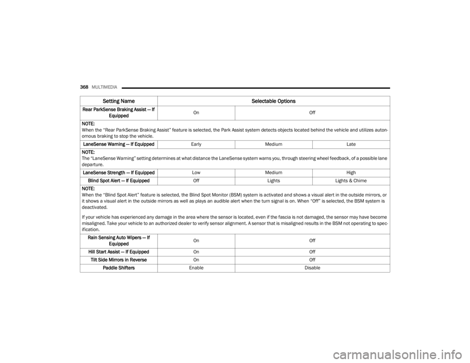
368MULTIMEDIA
Rear ParkSense Braking Assist — If
Equipped On
Off
NOTE:
When the “Rear ParkSense Braking Assist” feature is selected, the Park Assist system detects objects located behind the vehicle and utilizes auton -
omous braking to stop the vehicle.
LaneSense Warning — If Equipped EarlyMedium Late
NOTE:
The “LaneSense Warning” setting determines at what distance the LaneSense system warns you, through steering wheel feedback, of a possible lane
departure. LaneSense Strength — If Equipped LowMedium High
Blind Spot Alert — If Equipped OffLightsLights & Chime
NOTE:
When the “Blind Spot Alert” feature is selected, the Blind Spot Monitor (BSM) system is activated and shows a visual alert in the outside mirrors, or
it shows a visual alert in the outside mirrors as well as plays an audible alert when the turn signal is on. When “Off” is selected, the BSM system is
deactivated.
If your vehicle has experienced any damage in the area where the sensor is located, even if the fascia is not damaged, the sensor may have become
misaligned. Take your vehicle to an authorized dealer to verify sensor alignment. A sensor that is misaligned results in the BSM not operating to spec -
ification.
Rain Sensing Auto Wipers — If Equipped On
Off
Hill Start Assist — If Equipped On Off
Tilt Side Mirrors in Reverse On Off
Paddle Shifters Enable Disable
Setting Name Selectable Options
20_WD_OM_EN_USC_t.book Page 368
Page 450 of 464

448
INDEX
A
About Your Brakes......................................... 350Adaptive Cruise Control (ACC)
(Cruise Control).............................................. 208Adding Engine Coolant (Antifreeze)............... 322Adding Fuel.................................................... 238Additives, Fuel............................................... 352Adjust
Down.................................................... 38, 39Forward................................................ 38, 39Rearward.............................................. 38, 39Up......................................................... 38, 39Air BagAir Bag Operation...................................... 156Air Bag Warning Light................................ 153Driver Knee Air Bag................................... 157Enhanced Accident Response......... 161, 293Event Data Recorder (EDR)....................... 293If Deployment Occurs................................ 160Knee Impact Bolsters................................ 156Maintaining Your Air Bag System.............. 161Maintenance............................................. 161Redundant Air Bag Warning Light.............154Side Air Bags............................................. 157Transporting Pets...................................... 180Air Bag Light............................... 110, 153, 181
Air Cleaner, Engine (Engine Air Cleaner
Filter)............................................................ 311Air Conditioner Maintenance........................ 313Air Conditioner Refrigerant........................... 313Air Conditioner System................................. 313Air Conditioning................................................ 68Rear............................................................. 66Air Conditioning Filter.................... 70, 311, 314Air Conditioning System................................... 69Air Conditioning, Operating Tips....................... 69Air Filter........................................................ 311Air PressureTires......................................................... 336AlarmArm The System................................... 23, 24Disarm The System..................................... 24Rearm The System...................................... 24Security Alarm.......................................... 113Alarm SystemSecurity Alarm............................................. 23All Wheel Drive (AWD)................................... 199Alterations/ModificationsVehicle......................................................... 11Android Auto................................................. 442Antifreeze (Engine Coolant)........ 322, 355, 356Disposal................................................... 323
Anti-Lock Brake System (ABS)....................... 122Anti-Lock Warning Light................................ 116Apple CarPlay................................................ 442Arming SystemSecurity Alarm.............................................23Assist, Hill Start............................................. 128Audio Settings............................................... 402Audio Systems (Radio).................................. 361Auto Down Power Windows..............................71Automatic Headlights.......................................52Automatic High Beams.....................................51Automatic Temperature Control (ATC)..............69Automatic Transmission....................... 184, 193Adding Fluid..................................... 326, 360Fluid And Filter Change............................. 326Fluid Change............................................. 326Fluid Level Check...................................... 326Fluid Type............................... 326, 358, 360Special Additives...................................... 326Automatic Transmission Limp Home Mode... 197Aux Mode...................................................... 405Auxiliary Driving Systems.............................. 131Auxiliary Electrical Outlet (Power Outlet)..........87Auxiliary Power Outlet......................................87Axle Fluid....................................................... 358Axle Lubrication............................................ 360
20_WD_OM_EN_USC_t.book Page 448