fuel cap DODGE DURANGO 2020 Owners Manual
[x] Cancel search | Manufacturer: DODGE, Model Year: 2020, Model line: DURANGO, Model: DODGE DURANGO 2020Pages: 464, PDF Size: 22.14 MB
Page 9 of 464
7
RAISING THE VEHICLE ..................................... 327
TIRES ................................................................... 327 Tire Safety Information .............................327Tires — General Information .....................335Tire Types ...................................................339
Spare Tires — If Equipped ........................ 340Wheel And Wheel Trim Care ...................342Tire Chains and Traction Devices —
Non-SRT .....................................................343 Tire Chains and Traction Devices —
SRT .............................................................344 Tire Rotation Recommendations .............344
DEPARTMENT OF TRANSPORTATION
UNIFORM TIRE QUALITY GRADES ................... 344
Treadwear .................................................. 345Traction Grades .........................................345
Temperature Grades .................................345
STORING THE VEHICLE ..................................... 346
BODYWORK ........................................................ 346
Protection From Atmospheric Agents ......346Body And Underbody Maintenance ..........346
Preserving The Bodywork ..........................347
INTERIORS ......................................................... 348
Seats And Fabric Parts .............................. 348
Plastic And Coated Parts ...........................348
Leather Parts .............................................349Glass Surfaces ..........................................349
TECHNICAL SPECIFICATIONS
IDENTIFICATION DATA .......................................350
Vehicle Identification Number .................. 350
BRAKE SYSTEM .................................................. 350
WHEEL AND TIRE TORQUE
SPECIFICATIONS ............................................... 350
Torque Specifications ................................ 350
FUEL REQUIREMENTS ......................................351
3.6L Engine ................................................ 351
5.7L Engine ................................................ 351
6.4L Engine ................................................ 352
Reformulated Gasoline .......................... 352Materials Added To Fuel .......................... 352Gasoline/Oxygenate Blends .................... 353
Do Not Use E-85 In Non-Flex Fuel
Vehicles ...................................................... 353 CNG And LP Fuel System Modifications... 353
MMT In Gasoline ........................................ 353
Fuel System Cautions................................ 354
Carbon Monoxide Warnings ..................... 354
FLUID CAPACITIES — NON-SRT ........................355
FLUID CAPACITIES — SRT ................................. 356
FLUIDS AND LUBRICANTS — NON-SRT ........... 357
Engine ........................................................ 357
Chassis ....................................................... 358
FLUIDS AND LUBRICANTS — SRT .................... 359
Engine ........................................................ 359
Chassis ...................................................... 360
MULTIMEDIA
UCONNECT SYSTEMS ........................................ 361
CYBERSECURITY ................................................ 361
UCONNECT SETTINGS ....................................... 362Customer Programmable Features —
Uconnect 4 Settings .................................. 363 Customer Programmable Features —
Uconnect 4C/4C NAV Settings ................. 377
SAFETY AND GENERAL INFORMATION .......... 394
Safety Guidelines....................................... 394
UCONNECT 4 WITH 7-INCH DISPLAY .............. 395
Introduction................................................ 395
Radio Mode ................................................ 396
Media Mode ............................................... 404
Phone Mode............................................... 411
STEERING WHEEL AUDIO CONTROLS ............ 423
Radio Operation......................................... 423Media Mode ............................................... 423
IPOD®/USB/MP3 CONTROL —
IF EQUIPPED ....................................................... 424
Connecting The AUX Audio Input Or
External USB Device .................................. 424 Using This Feature..................................... 424
Second Row USB Charging Port ............... 425
20_WD_OM_EN_USC_t.book Page 7
Page 98 of 464
96GETTING TO KNOW YOUR INSTRUMENT PANEL
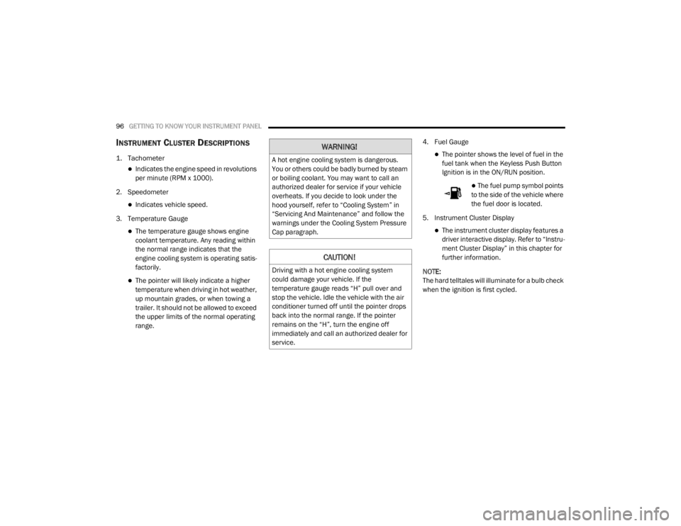
INSTRUMENT CLUSTER DESCRIPTIONS
1. Tachometer
Indicates the engine speed in revolutions
per minute (RPM x 1000).
2. Speedometer
Indicates vehicle speed.
3. Temperature Gauge
The temperature gauge shows engine
coolant temperature. Any reading within
the normal range indicates that the
engine cooling system is operating satis -
factorily.
The pointer will likely indicate a higher
temperature when driving in hot weather,
up mountain grades, or when towing a
trailer. It should not be allowed to exceed
the upper limits of the normal operating
range. 4. Fuel Gauge
The pointer shows the level of fuel in the
fuel tank when the Keyless Push Button
Ignition is in the ON/RUN position.
The fuel pump symbol points
to the side of the vehicle where
the fuel door is located.
5. Instrument Cluster Display
The instrument cluster display features a
driver interactive display. Refer to “Instru -
ment Cluster Display” in this chapter for
further information.
NOTE:
The hard telltales will illuminate for a bulb check
when the ignition is first cycled.
WARNING!
A hot engine cooling system is dangerous.
You or others could be badly burned by steam
or boiling coolant. You may want to call an
authorized dealer for service if your vehicle
overheats. If you decide to look under the
hood yourself, refer to “Cooling System” in
“Servicing And Maintenance” and follow the
warnings under the Cooling System Pressure
Cap paragraph.
CAUTION!
Driving with a hot engine cooling system
could damage your vehicle. If the
temperature gauge reads “H” pull over and
stop the vehicle. Idle the vehicle with the air
conditioner turned off until the pointer drops
back into the normal range. If the pointer
remains on the “H”, turn the engine off
immediately and call an authorized dealer for
service.
20_WD_OM_EN_USC_t.book Page 96
Page 100 of 464
98GETTING TO KNOW YOUR INSTRUMENT PANEL
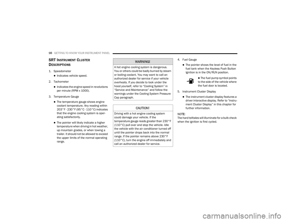
SRT INSTRUMENT CLUSTER
D
ESCRIPTIONS
1. Speedometer
Indicates vehicle speed.
2. Tachometer
Indicates the engine speed in revolutions
per minute (RPM x 1000).
3. Temperature Gauge
The temperature gauge shows engine
coolant temperature. Any reading within
203°F - 230°F (95°C - 110°C) indicates
that the engine cooling system is oper -
ating satisfactorily.
The pointer will likely indicate a higher
temperature when driving in hot weather,
up mountain grades, or when towing a
trailer. It should not be allowed to exceed
the upper limits of the normal operating
range. 4. Fuel Gauge
The pointer shows the level of fuel in the
fuel tank when the Keyless Push Button
Ignition is in the ON/RUN position.
The fuel pump symbol points
to the side of the vehicle where
the fuel door is located.
5. Instrument Cluster Display
The instrument cluster display features a
driver interactive display. Refer to “Instru -
ment Cluster Display” in this chapter for
further information.
NOTE:
The hard telltales will illuminate for a bulb check
when the ignition is first cycled.
WARNING!
A hot engine cooling system is dangerous.
You or others could be badly burned by steam
or boiling coolant. You may want to call an
authorized dealer for service if your vehicle
overheats. If you decide to look under the
hood yourself, refer to “Cooling System” in
“Service and Maintenance” and follow the
warnings under the Cooling System Pressure
Cap paragraph.
CAUTION!
Driving with a hot engine cooling system
could damage your vehicle. If the
temperature gauge reads greater than 230°F
(110°C) pull over and stop the vehicle. Idle
the vehicle with the air conditioner turned off
until the pointer drops back into the normal
range. If the pointer remains above 230°F
(110°C), turn the engine off immediately and
call an authorized dealer for service.
20_WD_OM_EN_USC_t.book Page 98
Page 115 of 464
GETTING TO KNOW YOUR INSTRUMENT PANEL113
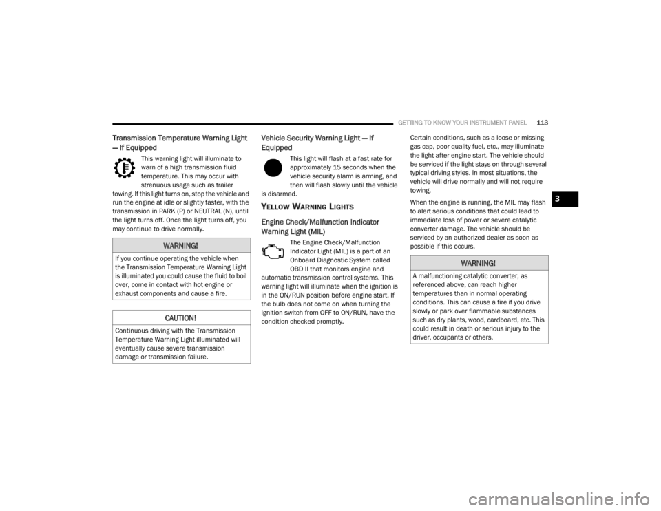
Transmission Temperature Warning Light
— If Equipped
This warning light will illuminate to
warn of a high transmission fluid
temperature. This may occur with
strenuous usage such as trailer
towing. If this light turns on, stop the vehicle and
run the engine at idle or slightly faster, with the
transmission in PARK (P) or NEUTRAL (N), until
the light turns off. Once the light turns off, you
may continue to drive normally.
Vehicle Security Warning Light — If
Equipped
This light will flash at a fast rate for
approximately 15 seconds when the
vehicle security alarm is arming, and
then will flash slowly until the vehicle
is disarmed.
YELLOW WARNING LIGHTS
Engine Check/Malfunction Indicator
Warning Light (MIL)
The Engine Check/Malfunction
Indicator Light (MIL) is a part of an
Onboard Diagnostic System called
OBD II that monitors engine and
automatic transmission control systems. This
warning light will illuminate when the ignition is
in the ON/RUN position before engine start. If
the bulb does not come on when turning the
ignition switch from OFF to ON/RUN, have the
condition checked promptly. Certain conditions, such as a loose or missing
gas cap, poor quality fuel, etc., may illuminate
the light after engine start. The vehicle should
be serviced if the light stays on through several
typical driving styles. In most situations, the
vehicle will drive normally and will not require
towing.
When the engine is running, the MIL may flash
to alert serious conditions that could lead to
immediate loss of power or severe catalytic
converter damage. The vehicle should be
serviced by an authorized dealer as soon as
possible if this occurs.WARNING!
If you continue operating the vehicle when
the Transmission Temperature Warning Light
is illuminated you could cause the fluid to boil
over, come in contact with hot engine or
exhaust components and cause a fire.
CAUTION!
Continuous driving with the Transmission
Temperature Warning Light illuminated will
eventually cause severe transmission
damage or transmission failure.
WARNING!
A malfunctioning catalytic converter, as
referenced above, can reach higher
temperatures than in normal operating
conditions. This can cause a fire if you drive
slowly or park over flammable substances
such as dry plants, wood, cardboard, etc. This
could result in death or serious injury to the
driver, occupants or others.
3
20_WD_OM_EN_USC_t.book Page 113
Page 142 of 464
140SAFETY
NOTE:
The TPMS is not intended to replace normal
tire care and maintenance, or to provide
warning of a tire failure or condition.
The TPMS should not be used as a tire pres -
sure gauge while adjusting your tire pressure.
Driving on a significantly under-inflated tire
causes the tire to overheat and can lead to
tire failure. Under-inflation also reduces fuel
efficiency and tire tread life, and may affect
the vehicle’s handling and stopping ability.
The TPMS is not a substitute for proper tire
maintenance, and it is the driver’s responsi -
bility to maintain correct tire pressure using
an accurate tire gauge, even if under-infla -
tion has not reached the level to trigger illu -
mination of the TPMS Warning Light.
Seasonal temperature changes will affect
tire pressure, and the TPMS will monitor the
actual tire pressure in the tire.
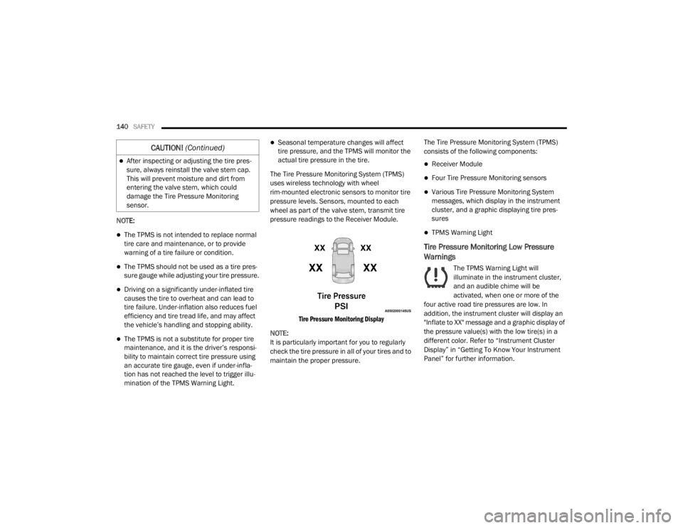
The Tire Pressure Monitoring System (TPMS)
uses wireless technology with wheel
rim-mounted electronic sensors to monitor tire
pressure levels. Sensors, mounted to each
wheel as part of the valve stem, transmit tire
pressure readings to the Receiver Module.
Tire Pressure Monitoring Display
NOTE:
It is particularly important for you to regularly
check the tire pressure in all of your tires and to
maintain the proper pressure. The Tire Pressure Monitoring System (TPMS)
consists of the following components:
Receiver Module
Four Tire Pressure Monitoring sensors
Various Tire Pressure Monitoring System
messages, which display in the instrument
cluster, and a graphic displaying tire pres
-
sures
TPMS Warning Light
Tire Pressure Monitoring Low Pressure
Warnings
The TPMS Warning Light will
illuminate in the instrument cluster,
and an audible chime will be
activated, when one or more of the
four active road tire pressures are low. In
addition, the instrument cluster will display an
"Inflate to XX" message and a graphic display of
the pressure value(s) with the low tire(s) in a
different color. Refer to “Instrument Cluster
Display” in “Getting To Know Your Instrument
Panel” for further information.
After inspecting or adjusting the tire pres -
sure, always reinstall the valve stem cap.
This will prevent moisture and dirt from
entering the valve stem, which could
damage the Tire Pressure Monitoring
sensor.
CAUTION! (Continued)
20_WD_OM_EN_USC_t.book Page 140
Page 241 of 464
STARTING AND OPERATING239
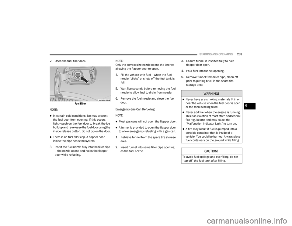
2. Open the fuel filler door.
Fuel Filler
NOTE:
In certain cold conditions, ice may prevent
the fuel door from opening. If this occurs,
lightly push on the fuel door to break the ice
buildup and re-release the fuel door using the
inside release button. Do not pry on the door.
There is no fuel filler cap. A flapper door
inside the pipe seals the system.
3. Insert the fuel nozzle fully into the filler pipe – the nozzle opens and holds the flapper
door while refueling. NOTE:
Only the correct size nozzle opens the latches
allowing the flapper door to open.
4. Fill the vehicle with fuel – when the fuel
nozzle “clicks” or shuts off the fuel tank is
full.
5. Wait five seconds before removing the fuel nozzle to allow fuel to drain from nozzle.
6. Remove the fuel nozzle and close the fuel door.
Emergency Gas Can Refueling
NOTE:
Most gas cans will not open the flapper door.
A funnel is provided to open the flapper door
to allow emergency refueling with a gas can.
1. Retrieve funnel from the spare tire storage area.
2. Insert funnel into same filler pipe opening as the fuel nozzle. 3. Ensure funnel is inserted fully to hold
flapper door open.
4. Pour fuel into funnel opening.
5. Remove funnel from filler pipe, clean off prior to putting back in the spare tire
storage area.
WARNING!
Never have any smoking materials lit in or
near the vehicle when the fuel door is open
or the tank is being filled.
Never add fuel when the engine is running.
This is in violation of most state and federal
fire regulations and may cause the
“Malfunction Indicator Light” to turn on.
A fire may result if fuel is pumped into a
portable container that is inside of a
vehicle. You could be burned. Always place
fuel containers on the ground while filling.
CAUTION!
To avoid fuel spillage and overfilling, do not
“top off” the fuel tank after filling.
5
20_WD_OM_EN_USC_t.book Page 239
Page 242 of 464
240STARTING AND OPERATING
EMERGENCY FUEL FILLER DOOR
R
ELEASE
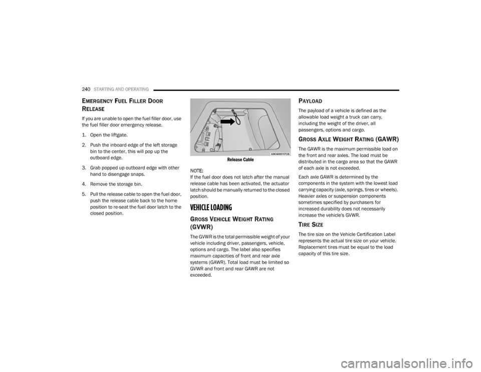
If you are unable to open the fuel filler door, use
the fuel filler door emergency release.
1. Open the liftgate.
2. Push the inboard edge of the left storage
bin to the center, this will pop up the
outboard edge.
3. Grab popped up outboard edge with other hand to disengage snaps.
4. Remove the storage bin.
5. Pull the release cable to open the fuel door, push the release cable back to the home
position to re-seat the fuel door latch to the
closed position.
Release Cable
NOTE:
If the fuel door does not latch after the manual
release cable has been activated, the actuator
latch should be manually returned to the closed
position.
VEHICLE LOADING
GROSS VEHICLE WEIGHT RATING
(GVWR)
The GVWR is the total permissible weight of your
vehicle including driver, passengers, vehicle,
options and cargo. The label also specifies
maximum capacities of front and rear axle
systems (GAWR). Total load must be limited so
GVWR and front and rear GAWR are not
exceeded.
PAYLOAD
The payload of a vehicle is defined as the
allowable load weight a truck can carry,
including the weight of the driver, all
passengers, options and cargo.
GROSS AXLE WEIGHT RATING (GAWR)
The GAWR is the maximum permissible load on
the front and rear axles. The load must be
distributed in the cargo area so that the GAWR
of each axle is not exceeded.
Each axle GAWR is determined by the
components in the system with the lowest load
carrying capacity (axle, springs, tires or wheels).
Heavier axles or suspension components
sometimes specified by purchasers for
increased durability does not necessarily
increase the vehicle's GVWR.
TIRE SIZE
The tire size on the Vehicle Certification Label
represents the actual tire size on your vehicle.
Replacement tires must be equal to the load
capacity of this tire size.
20_WD_OM_EN_USC_t.book Page 240
Page 243 of 464
STARTING AND OPERATING241
RIM SIZE
This is the rim size that is appropriate for the tire
size listed.
INFLATION PRESSURE
This is the cold tire inflation pressure for your
vehicle for all loading conditions up to full
GAWR.
CURB WEIGHT
The curb weight of a vehicle is defined as the
total weight of the vehicle with all fluids,
including vehicle fuel, at full capacity
conditions, and with no occupants or cargo
loaded into the vehicle. The front and rear curb
weight values are determined by weighing your
vehicle on a commercial scale before any
occupants or cargo are added.
LOADING
The actual total weight and the weight of the
front and rear of your vehicle at the ground can
best be determined by weighing it when it is
loaded and ready for operation. The entire vehicle should first be weighed on a
commercial scale to ensure that the GVWR has
not been exceeded. The weight on the front and
rear of the vehicle should then be determined
separately to be sure that the load is properly
distributed over the front and rear axle.
Weighing the vehicle may show that the GAWR
of either the front or rear axles has been
exceeded but the total load is within the
specified GVWR. If so, weight must be shifted
from front to rear or rear to front as appropriate
until the specified weight limitations are met.
Store the heavier items down low and be sure
that the weight is distributed equally. Stow all
loose items securely before driving.
Improper weight distributions can have an
adverse effect on the way your vehicle steers
and handles and the way the brakes operate.
TRAILER TOWING
In this section you will find safety tips and
information on limits to the type of towing you
can reasonably do with your vehicle. Before
towing a trailer, carefully review this information
to tow your load as efficiently and safely as
possible.
To maintain the New Vehicle Limited Warranty
coverage, follow the requirements and
recommendations in this manual concerning
vehicles used for trailer towing.
COMMON TOWING DEFINITIONS
The following trailer towing related definitions
will assist you in understanding the following
information:
Gross Vehicle Weight Rating (GVWR)
The GVWR is the total allowable weight of your
vehicle. This includes driver, passengers, cargo
and tongue weight. The total load must be
limited so that you do not exceed the GVWR.
Refer to “Vehicle Loading/Vehicle Certification
Label” in this chapter for further information.CAUTION!
Do not load your vehicle any heavier than the
GVWR or the maximum front and rear GAWR.
If you do, parts on your vehicle can break, or
it can change the way your vehicle handles.
This could cause you to lose control. Also
overloading can shorten the life of your
vehicle.
5
20_WD_OM_EN_USC_t.book Page 241
Page 275 of 464
IN CASE OF EMERGENCY273
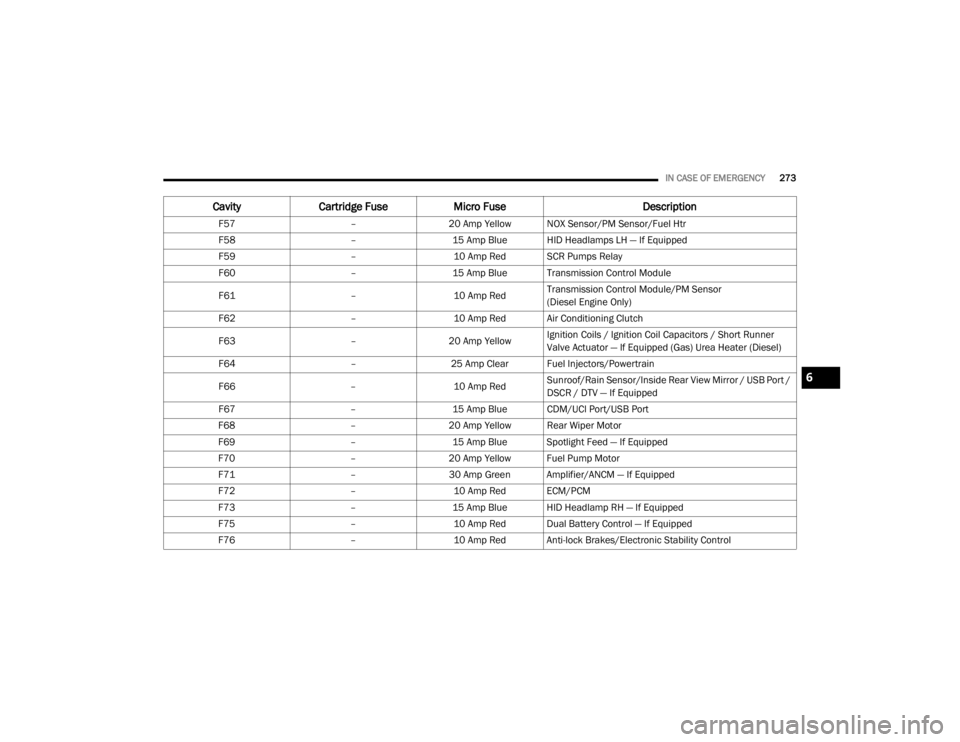
F57 –20 Amp Yellow NOX Sensor/PM Sensor/Fuel Htr
F58 –15 Amp Blue HID Headlamps LH — If Equipped
F59 –10 Amp Red SCR Pumps Relay
F60 –15 Amp Blue Transmission Control Module
F61 –10 Amp RedTransmission Control Module/PM Sensor
(Diesel Engine Only)
F62 –10 Amp Red Air Conditioning Clutch
F63 –20 Amp Yellow Ignition Coils / Ignition Coil Capacitors / Short Runner
Valve Actuator — If Equipped (Gas) Urea Heater (Diesel)
F64 –25 Amp Clear Fuel Injectors/Powertrain
F66 –10 Amp RedSunroof/Rain Sensor/Inside Rear View Mirror / USB Port /
DSCR / DTV — If Equipped
F67 –15 Amp Blue CDM/UCI Port/USB Port
F68 –20 Amp Yellow Rear Wiper Motor
F69 –15 Amp Blue Spotlight Feed — If Equipped
F70 –20 Amp Yellow Fuel Pump Motor
F71 –30 Amp Green Amplifier/ANCM — If Equipped
F72 –10 Amp Red ECM/PCM
F73 –15 Amp Blue HID Headlamp RH — If Equipped
F75 –10 Amp Red Dual Battery Control — If Equipped
F76 –10 Amp Red Anti-lock Brakes/Electronic Stability Control
CavityCartridge Fuse Micro Fuse Description
6
20_WD_OM_EN_USC_t.book Page 273
Page 312 of 464
310SERVICING AND MAINTENANCE
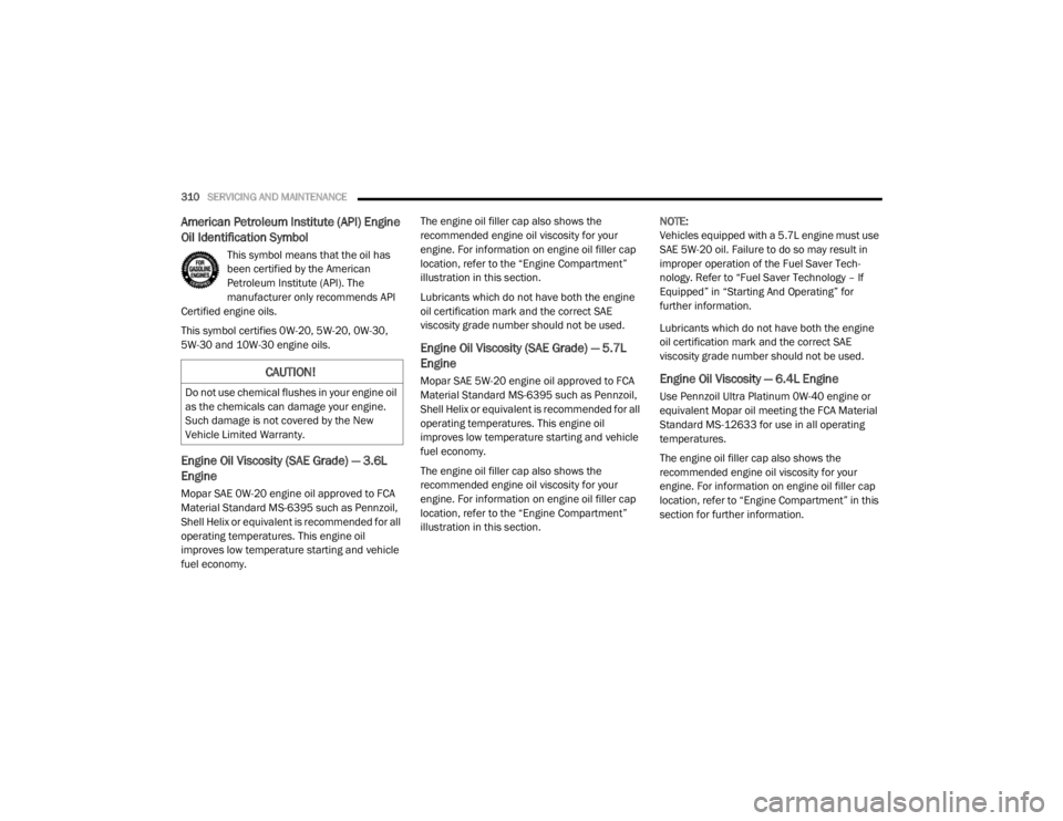
American Petroleum Institute (API) Engine
Oil Identification Symbol
This symbol means that the oil has
been certified by the American
Petroleum Institute (API). The
manufacturer only recommends API
Certified engine oils.
This symbol certifies 0W-20, 5W-20, 0W-30,
5W-30 and 10W-30 engine oils.
Engine Oil Viscosity (SAE Grade) — 3.6L
Engine
Mopar SAE 0W-20 engine oil approved to FCA
Material Standard MS-6395 such as Pennzoil,
Shell Helix or equivalent is recommended for all
operating temperatures. This engine oil
improves low temperature starting and vehicle
fuel economy. The engine oil filler cap also shows the
recommended engine oil viscosity for your
engine. For information on engine oil filler cap
location, refer to the “Engine Compartment”
illustration in this section.
Lubricants which do not have both the engine
oil certification mark and the correct SAE
viscosity grade number should not be used.
Engine Oil Viscosity (SAE Grade) — 5.7L
Engine
Mopar SAE 5W-20 engine oil approved to FCA
Material Standard MS-6395 such as Pennzoil,
Shell Helix or equivalent is recommended for all
operating temperatures. This engine oil
improves low temperature starting and vehicle
fuel economy.
The engine oil filler cap also shows the
recommended engine oil viscosity for your
engine. For information on engine oil filler cap
location, refer to the “Engine Compartment”
illustration in this section.
NOTE:
Vehicles equipped with a 5.7L engine must use
SAE 5W-20 oil. Failure to do so may result in
improper operation of the Fuel Saver Tech
-
nology. Refer to “Fuel Saver Technology – If
Equipped” in “Starting And Operating” for
further information.
Lubricants which do not have both the engine
oil certification mark and the correct SAE
viscosity grade number should not be used.Engine Oil Viscosity — 6.4L Engine
Use Pennzoil Ultra Platinum 0W-40 engine or
equivalent Mopar oil meeting the FCA Material
Standard MS-12633 for use in all operating
temperatures.
The engine oil filler cap also shows the
recommended engine oil viscosity for your
engine. For information on engine oil filler cap
location, refer to “Engine Compartment” in this
section for further information.
CAUTION!
Do not use chemical flushes in your engine oil
as the chemicals can damage your engine.
Such damage is not covered by the New
Vehicle Limited Warranty.
20_WD_OM_EN_USC_t.book Page 310