headlamp DODGE DURANGO 2020 Owners Manual
[x] Cancel search | Manufacturer: DODGE, Model Year: 2020, Model line: DURANGO, Model: DODGE DURANGO 2020Pages: 464, PDF Size: 22.14 MB
Page 53 of 464

GETTING TO KNOW YOUR VEHICLE51
NOTE:
Your vehicle is equipped with plastic head -
light and fog light (if equipped) lenses that
are lighter and less susceptible to stone
breakage than glass lights. Plastic is not as
scratch resistant as glass and therefore
different lens cleaning procedures must be
followed.
To minimize the possibility of scratching the
lenses and reducing light output, avoid
wiping with a dry cloth. To remove road dirt,
wash with a mild soap solution followed by
rinsing.
DAYTIME RUNNING LIGHTS (DRLS) —
I
F EQUIPPED
The Daytime Running Lights (DRLs) come on
whenever the engine is running, and the
transmission is not in the PARK position. The lights will remain on until the ignition is
placed in the OFF or ACC position, or the parking
brake is engaged. The headlight switch must be
used for normal night time driving.
NOTE:
If allowed by law in the country in which the
vehicle was purchased, the Daytime Running
Lights can be turned on and off using the
Uconnect system, refer to “Uconnect
Settings” in “Multimedia” for further informa
-
tion.
On some vehicles, the Daytime Running
Lights may deactivate, or reduce intensity, on
one side of the vehicle (when a turn signal is
activated on that side), or on both sides of
the vehicle (when the hazard warning lights
are activated).
HIGH/LOW BEAM SWITCH
Push the multifunction lever toward the
instrument panel to switch the headlights to
high beams. Pulling the multifunction back
toward the steering wheel will turn the low
beams back on, or shut the high beams off.
AUTOMATIC HIGH BEAM — IF EQUIPPED
The Automatic High Beam Headlamp Control
system provides increased forward lighting at
night by automating high beam control through
the use of a digital camera mounted on the
inside rearview mirror. This camera detects
vehicle specific light and automatically switches
from high beams to low beams until the
approaching vehicle is out of view.
NOTE:
The Automatic High Beam Headlamp Control
can be turned on or off by selecting or dese -
lecting “Auto High Beam” within your Ucon -
nect settings, as well as turning the headlight
switch to the AUTO position. Refer to “Ucon -
nect Settings” in “Multimedia” for further
information.
Broken, muddy, or obstructed headlights and
taillights of vehicles in the field of view will
cause headlights to remain on longer (closer
to the vehicle). Also, dirt, film, and other
obstructions on the windshield or camera
lens will cause the system to function
improperly.
CAUTION!
Do not use abrasive cleaning components,
solvents, steel wool or other abrasive
materials to clean the lenses.
2
20_WD_OM_EN_USC_t.book Page 51
Page 54 of 464

52GETTING TO KNOW YOUR VEHICLE
If the windshield or Automatic High Beam
Headlamp Control mirror is replaced, the mirror
must be re-aimed to ensure proper
performance. See a local authorized dealer.
FLASH-TO-PASS
You can signal another vehicle with your
headlights by lightly pulling the multifunction
lever toward you. This will cause the high beam
headlights to turn on, and remain on, until the
lever is released.
AUTOMATIC HEADLIGHTS
This system automatically turns the headlights
on or off according to ambient light levels. To
turn the system on, rotate the headlight switch
counterclockwise to the AUTO position. When
the system is on, the headlight time delay
feature is also on. This means the headlights
will stay on for up to 90 seconds after you place
the ignition into the OFF position. The headlight
time delay can be programmed 0/30/60/
90 seconds.
Refer to “Uconnect Settings” in “Multimedia”
for further information.
To turn the automatic system off, move the
headlight switch out of the AUTO position. NOTE:
The engine must be running before the head
-
lights will come on in the automatic mode.
PARKING LIGHTS AND PANEL LIGHTS
To turn on the parking lights and instrument
panel lights, rotate the headlight switch
clockwise. To turn off the parking lights, rotate
the headlight switch back to the O (off) position.
HEADLIGHTS ON AUTOMATICALLY WITH
W
IPERS
If your vehicle is equipped with Automatic
Headlights, it also has this
customer-programmable feature. When your
headlights are in the automatic mode and the
engine is running, they will automatically turn
on when the wiper system is on. This feature is
programmable through the Uconnect system.
Refer to “Uconnect Settings” in “Multimedia”
for further information.
NOTE:
When your headlights come on during the
daytime, the vehicle will monitor outside bright -
ness and decide if the instrument panel needs
to be dimmed or not. Refer to “Interior Lights” in
this chapter for further information.
HEADLIGHT DELAY
To aid in your exit, your vehicle is equipped with
a headlight delay that will leave the headlights
on for approximately 90 seconds. This delay is
initiated when the ignition is placed in the OFF
position while the headlight switch is on, and
then the headlight switch is cycled off.
Headlight delay can be canceled by either
turning the headlight switch on then off, or by
placing the ignition in the ON position.
NOTE:
The headlight delay time is programmable
through the Uconnect System. Refer to “Ucon -
nect Settings” in “Multimedia” for further infor -
mation.
LIGHTS-ON REMINDER
If the headlights, parking lights, or cargo lights
are left on after the ignition is placed in the OFF
position, a chime will sound when the driver’s
door is opened.
20_WD_OM_EN_USC_t.book Page 52
Page 163 of 464

SAFETY161
(Continued)
Enhanced Accident Response System
In the event of an impact, if the communication
network remains intact, and the power remains
intact, depending on the nature of the event,
the Occupant Restraint Controller (ORC) will
determine whether to have the Enhanced
Accident Response System perform the
following functions:
Cut off fuel to the engine (if equipped)
Cut off battery power to the electric motor (if
equipped)
Flash hazard lights as long as the battery has
power
Turn on the interior lights, which remain on
as long as the battery has power or for
15 minutes from the intervention of the
Enhanced Accident Response System
Unlock the power door locks
Your vehicle may also be designed to perform
any of these other functions in response to the
Enhanced Accident Response System:
Turn off the Fuel Filter Heater, Turn off the
HVAC Blower Motor, Close the HVAC Circula -
tion Door
Cut off battery power to the:
Engine
Electric Motor (if equipped)
Electric power steering
Brake booster
Electric park brake
Automatic transmission gear selector
Horn
Front wiper
Headlamp washer pump
NOTE:
After an accident, remember to cycle the igni -
tion to the STOP (OFF/LOCK) position and
remove the key from the ignition switch to avoid
draining the battery. Carefully check the vehicle
for fuel leaks in the engine compartment and on
the ground near the engine compartment and
fuel tank before resetting the system and
starting the engine. If there are no fuel leaks or
damage to the vehicle electrical devices (e.g.
headlights) after an accident, reset the system
by following the procedure described below. If you have any doubt, contact an authorized
dealer.
Enhanced Accident Response System
Reset Procedure
In order to reset the Enhanced Accident
Response System functions after an event, the
ignition switch must be changed from ignition
START or ON/RUN to ignition OFF. Carefully
check the vehicle for fuel leaks in the engine
compartment and on the ground near the
engine compartment and fuel tank before
resetting the system and starting the engine.
Maintaining Your Air Bag System
WARNING!
Modifications to any part of the air bag
system could cause it to fail when you need
it. You could be injured if the air bag system
is not there to protect you. Do not modify
the components or wiring, including adding
any kind of badges or stickers to the
steering wheel hub trim cover or the upper
passenger side of the instrument panel. Do
not modify the front bumper, vehicle body
structure, or add aftermarket side steps or
running boards.
4
20_WD_OM_EN_USC_t.book Page 161
Page 240 of 464

238STARTING AND OPERATING
The following table shows the approximate
distances for each zone:
NOTE:
If snow, ice, mud, or any foreign substance
builds up on the camera lens, clean the lens,
rinse with water, and dry with a soft cloth. Do
not cover the lens.
Rear Camera — Viewing At Speed When the vehicle is in PARK,
NEUTRAL or DRIVE, the Rear View
Camera can be activated with the
“Backup Camera” button in the
Controls menu. This feature allows the customer to monitor the
area directly behind the vehicle (or trailer, if
equipped) for up to 10 seconds while driving. If
the vehicle speed remains below 8 mph
(13 km/h), the Rear View Camera image will be
displayed continuously until deactivated via the
“X” button on the touchscreen.
REFUELING THE VEHICLE
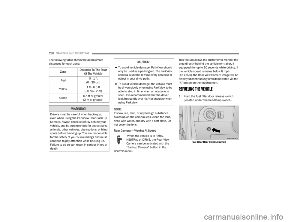
1. Push the fuel filler door release switch
(located under the headlamp switch).
Fuel Filler Door Release Switch
Zone
Distance To The Rear
Of The Vehicle
Red 0 - 1 ft
(0 - 30 cm)
Yellow 1 ft - 6.5 ft
(30 cm - 2 m)
Green 6.5 ft or greater
(2 m or greater)
WARNING!
Drivers must be careful when backing up
even when using the ParkView Rear Back Up
Camera. Always check carefully behind your
vehicle, and be sure to check for pedestrians,
animals, other vehicles, obstructions, or blind
spots before backing up. You are responsible
for the safety of your surroundings and must
continue to pay attention while backing up.
Failure to do so can result in serious injury or
death.
CAUTION!
To avoid vehicle damage, ParkView should
only be used as a parking aid. The ParkView
camera is unable to view every obstacle or
object in your drive path.
To avoid vehicle damage, the vehicle must
be driven slowly when using ParkView to be
able to stop in time when an obstacle is
seen. It is recommended that the driver
look frequently over his/her shoulder when
using ParkView.
20_WD_OM_EN_USC_t.book Page 238
Page 269 of 464

IN CASE OF EMERGENCY267
Exterior Bulbs
Bulb Name Bulb Number
Low Beam/High Beam (Bi-Xenon) Headlamps D3S (Serviced at an Authorized Dealer)
Low Beam/High Beam/Daytime Running Lamp (DRL) Bi-Halogen
Headlamps (Base) 9005SL+
Low Beam/High Beam (Bi-Halogen) Headlamps (Uplevel) 9005SL+
Front Park/Turn Signal Lamps (Base) 3157NAK
Front Turn Signal Lamps (Uplevel & Premium) 3157NAK
Front Park Lamp/Daytime Running Lamp (Uplevel & Premium) LED (Serviced at an Authorized Dealer)
Front Side Marker Lamps LED (Serviced at an Authorized Dealer)
Front Fog Lamps H11
Rear Tail Lamps/Side marker Lamps LED (Serviced at an Authorized Dealer)
Rear Stop/Turn Signal Lamps LED (Serviced at an Authorized Dealer)
Rear Liftgate Tail Lamps LED (Serviced at an Authorized Dealer)
Rear Backup Lamps 921 (W16W)
Rear License Lamps LED (Serviced at an Authorized Dealer)
Center High Mounted Stop Lamp (CHMSL) LED (Serviced at an Authorized Dealer)
6
20_WD_OM_EN_USC_t.book Page 267
Page 270 of 464

268IN CASE OF EMERGENCY
BULB REPLACEMENT
NOTE:
Lens fogging can occur under certain atmo -
spheric conditions. This will usually clear as
atmospheric conditions change to allow the
condensation to change back into a vapor.
Turning the lamps on will usually accelerate the
clearing process.
High Intensity Discharge Headlamps
(Bi-Xenon) — If Equipped
The headlamps are a type of high voltage
discharge tube. High voltage can remain in the
circuit even with the headlamp switch off.
Because of this, you should not attempt to
service a headlamp bulb yourself. If a headlamp
bulb fails, take your vehicle to an authorized
dealer for service. NOTE:
On vehicles equipped with High Intensity
Discharge (HID) headlamps, when the head
-
lamps are turned on, there is a blue hue to the
lamps. This diminishes and becomes more
white after approximately 10 seconds, as the
system charges.
Bi-Halogen Headlamps — If Equipped
1. Turn the steering wheel to the left to replace the bulb from the right hand lamp,
or to the right to replace the bulb from the
left hand lamp.
2. Turn the access cap located on the wheel liner counterclockwise to remove from liner.
3. Locate the headlamp bulb access cap through the opening in the wheel liner.
4. Firmly grasp the access cap and rotate counterclockwise to remove lamp housing. 5. Firmly grasp the low/high beam bulb and
connector assembly and rotate counter -
clockwise to remove from housing.
6. Disconnect the electrical connector and then connect the replacement bulb.
7. Install the bulb and connector assembly into the headlamp housing and rotate
clockwise to lock in place.
8. Install the bulb access cap in the headlamp housing and rotate clockwise to lock it in
place.
9. Install the access cap in the wheel liner and rotate clockwise to lock it in place.
WARNING!
A transient high voltage occurs at the bulb
sockets of High Intensity Discharge (HID)
headlamps when the headlamp switch is
turned ON. It may cause serious electrical
shock or electrocution if not serviced
properly. See an authorized dealer for
service.
CAUTION!
Do not touch the new bulb with your fingers.
Oil contamination will severely shorten bulb
life. If the bulb comes in contact with an oily
surface, clean the bulb with rubbing alcohol.
20_WD_OM_EN_USC_t.book Page 268
Page 273 of 464

IN CASE OF EMERGENCY271
CavityCartridge Fuse Micro Fuse Description
F0360 Amp Yellow –Radiator Fan — If Equipped
F05 40 Amp Green –Compressor for Air Suspension — If Equipped
F06 40 Amp Green –ABS Pump Mtr
F07 30 Amp Pink –Starter Solenoid
F09 30 Amp Pink –Diesel Fuel Heater (Diesel Engine Only)/Brake Vacuum
Pump
F10 40 Amp Green –CBC #2/Exterior Lighting
F11 30 Amp Pink –Trailer Tow Electric Brake — If Equipped
F12 40 Amp Green –CBC #3/Power Locks
F13 40 Amp Green –Blower Motor Front
F14 40 Amp Green –Body Controller #4/Exterior Lighting #1
F15 40 Amp Green –Low Temperature Radiator (LTR) Engine Cooling Pump — If
Equipped
F17 30 Amp Pink –Headlamp Washer — If Equipped
F19 20 Amp Blue –Headrest Solenoid — If Equipped
F20 30 Amp Pink –Passenger Door Module
F22 20 Amp Blue –Engine Control Module
F23 30 Amp Pink –CBC #1/Interior Lights
F24 30 Amp Pink –Driver Door Module
F25 30 Amp Pink –Front Wipers
F26 30 Amp Pink –ESP/ECU Valves
6
20_WD_OM_EN_USC_t.book Page 271
Page 274 of 464

272IN CASE OF EMERGENCY
F2820 Amp Blue –Trailer Tow Backup Lights — If Equipped
F29 20 Amp Blue –Trailer Tow Parking Lights — If Equipped
F30 30 Amp Pink –Trailer Tow (Receptacle) / Trailer Tow (Separate E-Brake) /
Trailer Tow (BUX) — If Equipped
F32 30 Amp Pink –Drive Train Control Module
F34 30 Amp Pink –Slip Differential Control — If Equipped
F35 30 Amp Pink –Sunroof - If Equipped
F36 30 Amp Pink –Rear Defroster/ Electronic BackLight (EBL)
F37 25 Amp Clear –Rear Blower Motor — If Equipped
F38 30 Amp Pink –Power Inverter 115 Volt AC — If Equipped
F39 30 Amp Pink –Power Liftgate — If Equipped
F40 –10 Amp Red Daytime Running Lights/Headlamp Leveling
F42 –20 Amp Yellow Horn
F44 –10 Amp Red Diagnostic Port
F45 –5 Amp Tan Cyber Security Gateway
F49 –10 Amp Red Integrated Central Stack/Climate Control
F50 –20 Amp Yellow Air Suspension Control Module/Slip Differential - If
Equipped
F51 –15 Amp Blue KIN/RF HUB/Steering Column Lock — If Equipped
F53 –20 Amp Yellow Trailer Tow – Left Turn/Stop Lights — If Equipped
F56 –15 Amp Blue PCM
CavityCartridge Fuse Micro Fuse Description
20_WD_OM_EN_USC_t.book Page 272
Page 275 of 464

IN CASE OF EMERGENCY273
F57 –20 Amp Yellow NOX Sensor/PM Sensor/Fuel Htr
F58 –15 Amp Blue HID Headlamps LH — If Equipped
F59 –10 Amp Red SCR Pumps Relay
F60 –15 Amp Blue Transmission Control Module
F61 –10 Amp RedTransmission Control Module/PM Sensor
(Diesel Engine Only)
F62 –10 Amp Red Air Conditioning Clutch
F63 –20 Amp Yellow Ignition Coils / Ignition Coil Capacitors / Short Runner
Valve Actuator — If Equipped (Gas) Urea Heater (Diesel)
F64 –25 Amp Clear Fuel Injectors/Powertrain
F66 –10 Amp RedSunroof/Rain Sensor/Inside Rear View Mirror / USB Port /
DSCR / DTV — If Equipped
F67 –15 Amp Blue CDM/UCI Port/USB Port
F68 –20 Amp Yellow Rear Wiper Motor
F69 –15 Amp Blue Spotlight Feed — If Equipped
F70 –20 Amp Yellow Fuel Pump Motor
F71 –30 Amp Green Amplifier/ANCM — If Equipped
F72 –10 Amp Red ECM/PCM
F73 –15 Amp Blue HID Headlamp RH — If Equipped
F75 –10 Amp Red Dual Battery Control — If Equipped
F76 –10 Amp Red Anti-lock Brakes/Electronic Stability Control
CavityCartridge Fuse Micro Fuse Description
6
20_WD_OM_EN_USC_t.book Page 273