interior lights DODGE DURANGO 2020 Owners Manual
[x] Cancel search | Manufacturer: DODGE, Model Year: 2020, Model line: DURANGO, Model: DODGE DURANGO 2020Pages: 464, PDF Size: 22.14 MB
Page 5 of 464

3
EXTERIOR LIGHTS ................................................50 Multifunction Lever ...................................... 50
Headlight Switch ......................................... 50
Daytime Running Lights (DRLs) —
If Equipped .................................................. 51 High/Low Beam Switch ............................... 51
Automatic High Beam — If Equipped .......... 51
Flash-To-Pass .............................................. 52
Automatic Headlights ................................. 52
Parking Lights And Panel Lights ................. 52
Headlights On Automatically With
Wipers........................................................... 52 Headlight Delay ............................................ 52
Lights-On Reminder ..................................... 52
Fog Lights — If Equipped ............................. 53
Turn Signals ................................................. 53
Lane Change Assist — If Equipped ............. 53
Battery Saver................................................ 53
INTERIOR LIGHTS ................................................54
Courtesy Lights ............................................ 54
WINDSHIELD WIPERS AND WASHERS .............55
Windshield Wiper Operation ....................... 55
Rain Sensing Wipers — If Equipped ........... 57
Rear Window Wiper/Washer ...................... 58
CLIMATE CONTROLS ............................................58
Automatic Climate Control Overview .......... 58
Climate Control Functions ........................... 68
Automatic Temperature Control (ATC) ....... 69
Operating Tips ............................................. 69 WINDOWS ............................................................ 71
Power Windows............................................ 71
Wind Buffeting ............................................ 72
POWER SUNROOF — IF EQUIPPED .................... 73
Opening Sunroof .......................................... 73
Closing Sunroof............................................ 74
Wind Buffeting ............................................ 74
Sunshade Operation.................................... 74
Pinch Protect Feature.................................. 74
Sunroof Maintenance.................................. 74
Ignition Off Operation .................................. 74
HOOD ..................................................................... 75
Opening The Hood ....................................... 75
Closing The Hood ......................................... 75
LIFTGATE ............................................................... 75
Power Liftgate — If Equipped ...................... 75
Cargo Area Features ................................... 77
GARAGE DOOR OPENER — IF EQUIPPED ......... 78
Before You Begin Programming
HomeLink® .................................................. 79 Canadian/Gate Operator Programming ..... 81
Using HomeLink®........................................ 82
Security......................................................... 82
Troubleshooting Tips ................................... 82
General Information .................................... 83
INTERNAL EQUIPMENT ........................................ 83
Storage ......................................................... 83
Cupholders ................................................... 86
Electrical Power Outlets ............................. 87
Power Inverter — If Equipped ...................... 90
Sunglasses Bin Door ................................... 90 ROOF LUGGAGE RACK — IF EQUIPPED ............90
Deploying The Crossbars ............................ 91
Stowing The Crossbars................................ 93
GETTING TO KNOW YOUR
INSTRUMENT PANEL
INSTRUMENT CLUSTER .......................................95Instrument Cluster Descriptions................. 96
SRT INSTRUMENT CLUSTER ...............................97
SRT Instrument Cluster Descriptions ......... 98
INSTRUMENT CLUSTER DISPLAY .......................99
Location And Controls ................................. 99
Engine Oil Life Reset ................................ 101
Display And Messages .............................. 102
Instrument Cluster Display Menu
Items .......................................................... 103 Battery Saver On/Battery Saver Mode
Message — Electrical Load Reduction
Actions — If Equipped ............................... 108
WARNING LIGHTS AND MESSAGES ............... 109
Red Warning Lights ................................... 110
Yellow Warning Lights ............................... 113Yellow Indicator Lights .............................. 117
Green Indicator Lights ............................... 117White Indicator Lights ............................... 119Blue Indicator Lights ................................. 119
20_WD_OM_EN_USC_t.book Page 3
Page 26 of 464

24GETTING TO KNOW YOUR VEHICLE
TO DISARM THE SYSTEM
The vehicle security alarm can be disarmed
using any of the following methods:
Push the unlock button on the key fob.
Grasp the Passive Entry unlock door handle
(if equipped). Refer to "Keyless Enter-N-Go —
Passive Entry" in “Doors” in this chapter for
further information.
Cycle the vehicle ignition system out of the
OFF position.
NOTE:
The driver's door key cylinder cannot arm or
disarm the vehicle security alarm. Use of the
door key cylinder when the alarm is armed
will sound the alarm when the door is
opened.
The vehicle security alarm remains armed
when the power liftgate is opened using the
liftgate button on the key fob. If someone
enters the vehicle through the liftgate and
opens any door from the inside, the alarm will
sound.
If Passive Entry (if equipped) is used to
unlock the liftgate, the vehicle security alarm
is disarmed and the rest of the vehicle doors
will remain locked unless “Unlock All Doors
1st Press” is selected in the Passive Entry
settings.
When the vehicle security alarm is armed,
the interior power door lock switches will not
unlock the doors.
The vehicle security alarm is designed to protect
your vehicle. However, you can create
conditions where the system will give you a false
alarm. If one of the previously described arming
sequences has occurred, the vehicle security
alarm will arm regardless of whether you are in
the vehicle or not. If you remain in the vehicle
and open a door, the alarm will sound. If this
occurs, disarm the vehicle security alarm.
If the vehicle security alarm is armed and the
battery becomes disconnected, the vehicle
security alarm will remain armed when the
battery is reconnected; the exterior lights will
flash, and the horn will sound. If this occurs,
disarm the vehicle security alarm.
REARMING OF THE SYSTEM
If something triggers the alarm, and no action is
taken to disarm it, the vehicle security alarm will
turn the horn off after 29 seconds, five seconds
between cycles, up to eight cycles if the trigger
remains active and the vehicle security alarm
will rearm itself.
TAMPER ALERT
If something has triggered the vehicle security
alarm in your absence, the horn will sound three
times and the exterior lights will blink three
times when you disarm the vehicle security
alarm. Check the vehicle for tampering.
DOORS
MANUAL DOOR LOCKS
The power door locks can be manually locked
from inside the vehicle by using the door lock
knob. To lock each door, push the door lock
knob on each door trim panel downward. To
unlock the front doors, pull the inside door
handle to the first detent.
20_WD_OM_EN_USC_t.book Page 24
Page 28 of 464

26GETTING TO KNOW YOUR VEHICLE
If you push the door lock switch while the
ignition position is in ACC or ON/RUN and the
driver or front passenger's door is open, the
doors will not lock.
If a rear door is locked, it cannot be opened
from inside the vehicle without first unlocking
the door. The door may be unlocked manually
by raising the lock knob.
KEYLESS ENTER-N-GO — PASSIVE
E
NTRY
The Passive Entry system is an enhancement to
the vehicle’s Remote Keyless Entry (RKE)
system and a feature of Keyless Enter-N-Go —
Passive Entry. This feature allows you to lock
and unlock the vehicle’s door(s) without having
to push the key fob lock or unlock buttons.
NOTE:
Passive Entry may be programmed on/off.
Refer to “Uconnect Settings” in “Multimedia”
for further information.
If wearing gloves on your hands, or if it has
been raining/snowing on the Passive Entry
door handle, the unlock sensitivity can be
affected, resulting in a slower response time.
If the vehicle is unlocked by Passive Entry
and no door is opened within 60 seconds, the
vehicle will re-lock and will arm the security
alarm (if equipped).
The key fob may not be able to be detected by
the vehicle Passive Entry system if it is
located next to a mobile phone, laptop or
other electronic device; these devices may
block the key fob's wireless signal and
prevent the passive entry handle from
locking/unlocking the vehicle.
Passive Entry activates illuminated approach
for the time set by the customer (0, 30, 60, or
90 seconds), and flashes the turn signal
lights. Refer to “Uconnect Settings” in “Multi -
media” for further information
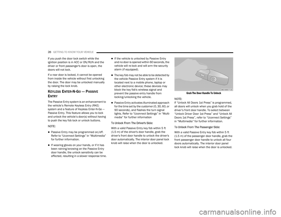
To Unlock From The Driver's Side:
With a valid Passive Entry key fob within 5 ft
(1.5 m) of the driver's door handle, grab the
driver's front door handle to unlock the driver's
door automatically. The interior door panel lock
knob will raise when the door is unlocked.
Grab The Door Handle To Unlock
NOTE:
If “Unlock All Doors 1st Press” is programmed,
all doors will unlock when you grab hold of the
driver’s front door handle. To select between
“Unlock Driver Door 1st Press” and “Unlock All
Doors 1st Press”, refer to “Uconnect Settings”
in “Multimedia” for further information.
To Unlock From The Passenger Side:
With a valid Passive Entry key fob within 5 ft
(1.5 m) of the passenger door handle, grab the
front passenger door handle to unlock all four
doors automatically. The interior door panel
lock knob will raise when the door is unlocked.
20_WD_OM_EN_USC_t.book Page 26
Page 54 of 464

52GETTING TO KNOW YOUR VEHICLE
If the windshield or Automatic High Beam
Headlamp Control mirror is replaced, the mirror
must be re-aimed to ensure proper
performance. See a local authorized dealer.
FLASH-TO-PASS
You can signal another vehicle with your
headlights by lightly pulling the multifunction
lever toward you. This will cause the high beam
headlights to turn on, and remain on, until the
lever is released.
AUTOMATIC HEADLIGHTS
This system automatically turns the headlights
on or off according to ambient light levels. To
turn the system on, rotate the headlight switch
counterclockwise to the AUTO position. When
the system is on, the headlight time delay
feature is also on. This means the headlights
will stay on for up to 90 seconds after you place
the ignition into the OFF position. The headlight
time delay can be programmed 0/30/60/
90 seconds.
Refer to “Uconnect Settings” in “Multimedia”
for further information.
To turn the automatic system off, move the
headlight switch out of the AUTO position. NOTE:
The engine must be running before the head
-
lights will come on in the automatic mode.
PARKING LIGHTS AND PANEL LIGHTS
To turn on the parking lights and instrument
panel lights, rotate the headlight switch
clockwise. To turn off the parking lights, rotate
the headlight switch back to the O (off) position.
HEADLIGHTS ON AUTOMATICALLY WITH
W
IPERS
If your vehicle is equipped with Automatic
Headlights, it also has this
customer-programmable feature. When your
headlights are in the automatic mode and the
engine is running, they will automatically turn
on when the wiper system is on. This feature is
programmable through the Uconnect system.
Refer to “Uconnect Settings” in “Multimedia”
for further information.
NOTE:
When your headlights come on during the
daytime, the vehicle will monitor outside bright -
ness and decide if the instrument panel needs
to be dimmed or not. Refer to “Interior Lights” in
this chapter for further information.
HEADLIGHT DELAY
To aid in your exit, your vehicle is equipped with
a headlight delay that will leave the headlights
on for approximately 90 seconds. This delay is
initiated when the ignition is placed in the OFF
position while the headlight switch is on, and
then the headlight switch is cycled off.
Headlight delay can be canceled by either
turning the headlight switch on then off, or by
placing the ignition in the ON position.
NOTE:
The headlight delay time is programmable
through the Uconnect System. Refer to “Ucon -
nect Settings” in “Multimedia” for further infor -
mation.
LIGHTS-ON REMINDER
If the headlights, parking lights, or cargo lights
are left on after the ignition is placed in the OFF
position, a chime will sound when the driver’s
door is opened.
20_WD_OM_EN_USC_t.book Page 52
Page 55 of 464

GETTING TO KNOW YOUR VEHICLE53
FOG LIGHTS — IF EQUIPPED
The fog lights are turned on by rotating the
headlight switch to the parking light or headlight
position and pushing in the headlight rotary
control.
Fog Light Operation
The fog lights will operate only when the parking
lights are on or when the vehicle headlights are
on low beam. An indicator light located in the
instrument cluster display will illuminate when
the fog lights are on. The fog lights will turn off
when the switch is pushed a second time, when
the headlight switch is rotated to the off
position, or the high beam is selected.
TURN SIGNALS
Move the multifunction lever up or down and
the arrows on each side of the instrument
cluster will flash to show proper operation of the
front and rear turn signal lights.
NOTE:
If either light remains on and does not flash, or
there is a very fast flash rate, check for a defec -
tive outside light bulb. If an indicator fails to
light when the lever is moved, it would suggest
that the indicator bulb is defective.
LANE CHANGE ASSIST — IF EQUIPPED
Tap the multifunction lever up or down once,
without moving beyond the detent, and the turn
signal (right or left) will flash three times then
automatically turn off.
BATTERY SAVER
To protect the life of your vehicle’s battery, load
shedding is provided for both the interior and
exterior lights.
If the ignition is placed in the OFF position and
any door is left ajar for 10 minutes or the
dimmer control is rotated all the way up to the
dome on position for 10 minutes, the interior
lights will automatically turn off.
NOTE:
Battery saver mode is canceled if the ignition is
in the ON position.
If the headlights remain on while the ignition is
placed in the OFF position, the exterior lights will
automatically turn off after eight minutes. If the
headlights are turned on and left on for eight
minutes while the ignition is in the OFF position,
the exterior lights will automatically turn off.
2
20_WD_OM_EN_USC_t.book Page 53
Page 56 of 464

54GETTING TO KNOW YOUR VEHICLE
INTERIOR LIGHTS
COURTESY LIGHTS
The courtesy lights can be turned on by pushing
the top corner of the lens. To turn the lights off,
push the lens a second time.
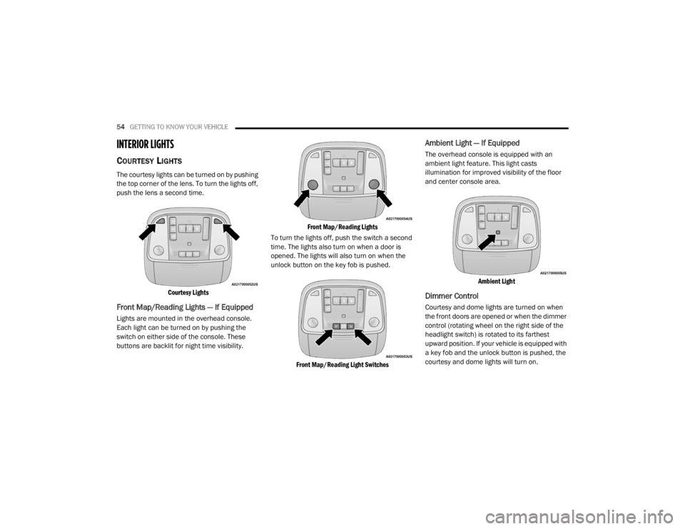
Courtesy Lights
Front Map/Reading Lights — If Equipped
Lights are mounted in the overhead console.
Each light can be turned on by pushing the
switch on either side of the console. These
buttons are backlit for night time visibility.
Front Map/Reading Lights
To turn the lights off, push the switch a second
time. The lights also turn on when a door is
opened. The lights will also turn on when the
unlock button on the key fob is pushed.
Front Map/Reading Light Switches
Ambient Light — If Equipped
The overhead console is equipped with an
ambient light feature. This light casts
illumination for improved visibility of the floor
and center console area.
Ambient Light
Dimmer Control
Courtesy and dome lights are turned on when
the front doors are opened or when the dimmer
control (rotating wheel on the right side of the
headlight switch) is rotated to its farthest
upward position. If your vehicle is equipped with
a key fob and the unlock button is pushed, the
courtesy and dome lights will turn on.
20_WD_OM_EN_USC_t.book Page 54
Page 57 of 464

GETTING TO KNOW YOUR VEHICLE55
When a door is open and the interior lights are
on, rotating the dimmer control all the way
down, to the (O) off detent, will cause all the
interior lights to go out. This is also known as
the “Party” mode because it allows the doors to
stay open for extended periods of time without
discharging the vehicle’s battery.
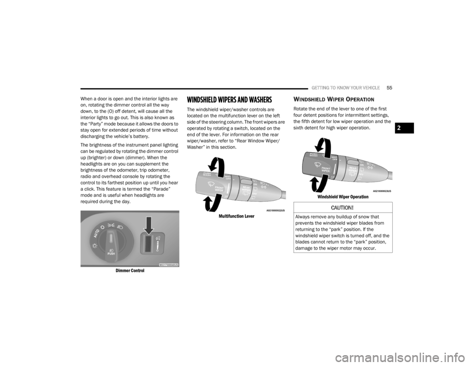
The brightness of the instrument panel lighting
can be regulated by rotating the dimmer control
up (brighter) or down (dimmer). When the
headlights are on you can supplement the
brightness of the odometer, trip odometer,
radio and overhead console by rotating the
control to its farthest position up until you hear
a click. This feature is termed the “Parade”
mode and is useful when headlights are
required during the day.
Dimmer Control
WINDSHIELD WIPERS AND WASHERS
The windshield wiper/washer controls are
located on the multifunction lever on the left
side of the steering column. The front wipers are
operated by rotating a switch, located on the
end of the lever. For information on the rear
wiper/washer, refer to “Rear Window Wiper/
Washer” in this section.
Multifunction Lever
WINDSHIELD WIPER OPERATION
Rotate the end of the lever to one of the first
four detent positions for intermittent settings,
the fifth detent for low wiper operation and the
sixth detent for high wiper operation.
Windshield Wiper Operation
CAUTION!
Always remove any buildup of snow that
prevents the windshield wiper blades from
returning to the “park” position. If the
windshield wiper switch is turned off, and the
blades cannot return to the “park” position,
damage to the wiper motor may occur.
2
20_WD_OM_EN_USC_t.book Page 55
Page 89 of 464

GETTING TO KNOW YOUR VEHICLE87
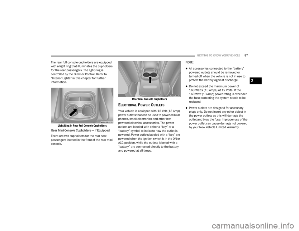
The rear full console cupholders are equipped
with a light ring that illuminates the cupholders
for the rear passengers. The light ring is
controlled by the Dimmer Control. Refer to
“Interior Lights” in this chapter for further
information.
Light Ring In Rear Full Console Cupholders
Rear Mini Console Cupholders — If Equipped
There are two cupholders for the rear seat
passengers located in the front of the rear mini
console.
Rear Mini Console Cupholders
ELECTRICAL POWER OUTLETS
Your vehicle is equipped with 12 Volt (13 Amp)
power outlets that can be used to power cellular
phones, small electronics and other low
powered electrical accessories. The power
outlets are labeled with either a “key” or a
“battery” symbol to indicate how the outlet is
powered. Power outlets labeled with a “key” are
powered when the ignition switch is in the ON or
ACC position, while the outlets labeled with a
“battery” are connected directly to the battery
and powered at all times.NOTE:
All accessories connected to the “battery”
powered outlets should be removed or
turned off when the vehicle is not in use to
protect the battery against discharge.
Do not exceed the maximum power of
160 Watts (13 Amps) at 12 Volts. If the
160 Watt (13 Amp) power rating is exceeded
the fuse protecting the system needs to be
replaced.
Power outlets are designed for accessory
plugs only. Do not insert any other object in
the power outlets as this will damage the
outlet and blow the fuse. Improper use of the
power outlet can cause damage not covered
by your New Vehicle Limited Warranty.
2
20_WD_OM_EN_USC_t.book Page 87
Page 110 of 464

108GETTING TO KNOW YOUR INSTRUMENT PANEL
SRT Speed Warning — If Equipped
Push and release the up or down arrow button
until the Speed Warning Menu icon/title is
highlighted in the instrument cluster display.
Push and release the OK button to enter speed
warning. Use the up or down arrow button to
select a desired speed, then push and release
the OK button to set the speed. When the set
speed is exceeded, the indication will light up
yellow and flash along with a pop-up message of
“Speed Warning Exceeded” with a continuous
chime (until the speed is no longer exceeded).
BATTERY SAVER ON/BATTERY SAVER
M
ODE MESSAGE — ELECTRICAL LOAD
R
EDUCTION ACTIONS — IF EQUIPPED
This vehicle is equipped with an Intelligent
Battery Sensor (IBS) to perform additional
monitoring of the electrical system and status
of the vehicle battery.
In cases when the IBS detects charging system
failure, or the vehicle battery conditions are
deteriorating, electrical load reduction actions
will take place to extend the driving time and
distance of the vehicle. This is done by reducing
power to or turning off non-essential electrical
loads. Load reduction is only active when the engine is
running. It will display a message if there is a
risk of battery depletion to the point where the
vehicle may stall due to lack of electrical supply,
or will not restart after the current drive cycle.
When load reduction is activated, the message
“Battery Saver On” or “Battery Saver Mode” will
appear in the instrument cluster.
These messages indicate the vehicle battery
has a low state of charge and continues to lose
electrical charge at a rate that the charging
system cannot sustain.
NOTE:
The charging system is independent from
load reduction. The charging system
performs a diagnostic on the charging
system continuously.
If the Battery Charge Warning Light is on it
may indicate a problem with the charging
system. Refer to “Battery Charge Warning
Light” in this chapter for further information.
The electrical loads that may be switched off
(if equipped), and vehicle functions which can
be affected by load reduction:
Heated Seat/Vented Seats/Heated Wheel
Rear Defroster And Heated Mirrors
HVAC System
115 Volt AC Power Inverter System
Audio and Telematics System
Loss of the battery charge may indicate one or
more of the following conditions:
The charging system cannot deliver enough
electrical power to the vehicle system
because the electrical loads are larger than
the capability of the charging system. The
charging system is still functioning properly.
Turning on all possible vehicle electrical
loads (e.g. HVAC to max settings, exterior and
interior lights, overloaded power outlets
+12 Volt, 115 Volt AC, USB ports) during
certain driving conditions (city driving,
towing, frequent stopping, etc.).
20_WD_OM_EN_USC_t.book Page 108
Page 111 of 464

GETTING TO KNOW YOUR INSTRUMENT PANEL109
Installing options like additional lights,
upfitter electrical accessories, audio
systems, alarms and similar devices.
Unusual driving cycles (short trips separated
by long parking periods).
The vehicle was parked for an extended
period of time (weeks, months).
The battery was recently replaced and was
not charged completely.
The battery was discharged by an electrical
load left on when the vehicle was parked.
The battery was used for an extended period
with the engine not running to supply radio,
lights, chargers, +12 Volt portable appli-
ances like vacuum cleaners, game consoles
and similar devices. What to do when an electrical load reduction
action message is present (“Battery Saver On”
or “Battery Saver Mode”)
During a trip:
Reduce power to unnecessary loads if
possible:
Turn off redundant lights (interior or exte
-
rior)
Check what may be plugged in to power
outlets +12 Volt, 115 Volt AC, USB ports
Check HVAC settings (blower, tempera -
ture)
Check the audio settings (volume)
After a trip:
Check if any aftermarket equipment was
installed (additional lights, upfitter electrical
accessories, audio systems, alarms) and
review specifications if any (load and Ignition
Off Draw currents).
Evaluate the latest driving cycles (distance,
driving time and parking time).
The vehicle should have service performed if
the message is still present during consecu -
tive trips, and if the evaluation and driving
pattern of the vehicle did not help to identify
the cause.
WARNING LIGHTS AND MESSAGES
The warning/indicator lights will illuminate in
the instrument panel together with a dedicated
message and/or acoustic signal when
applicable. These indications are indicative and
precautionary and as such must not be
considered as exhaustive and/or alternative to
the information contained in the Owner’s
Manual, which you are advised to read carefully
in all cases. Always refer to the information in
this chapter in the event of a failure indication.
All active telltales will display first if applicable.
The system check menu may appear different
based upon equipment options and current
vehicle status. Some telltales are optional and
may not appear.3
20_WD_OM_EN_USC_t.book Page 109