headlights DODGE DURANGO 2020 Owners Manual
[x] Cancel search | Manufacturer: DODGE, Model Year: 2020, Model line: DURANGO, Model: DODGE DURANGO 2020Pages: 464, PDF Size: 22.14 MB
Page 5 of 464
3
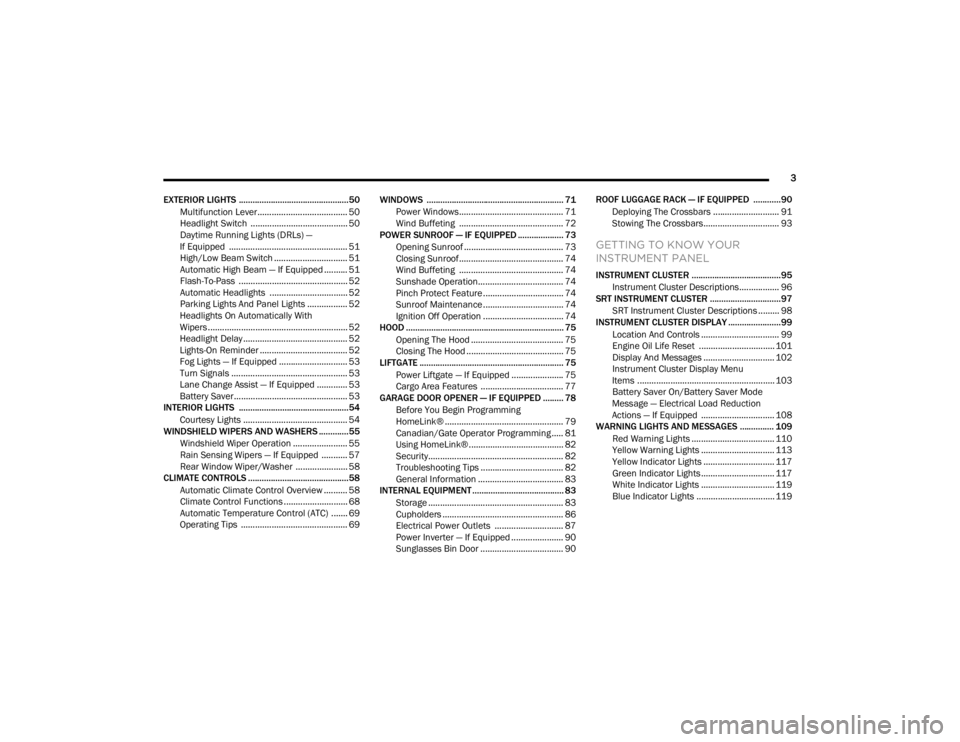
EXTERIOR LIGHTS ................................................50 Multifunction Lever ...................................... 50
Headlight Switch ......................................... 50
Daytime Running Lights (DRLs) —
If Equipped .................................................. 51 High/Low Beam Switch ............................... 51
Automatic High Beam — If Equipped .......... 51
Flash-To-Pass .............................................. 52
Automatic Headlights ................................. 52
Parking Lights And Panel Lights ................. 52
Headlights On Automatically With
Wipers........................................................... 52 Headlight Delay ............................................ 52
Lights-On Reminder ..................................... 52
Fog Lights — If Equipped ............................. 53
Turn Signals ................................................. 53
Lane Change Assist — If Equipped ............. 53
Battery Saver................................................ 53
INTERIOR LIGHTS ................................................54
Courtesy Lights ............................................ 54
WINDSHIELD WIPERS AND WASHERS .............55
Windshield Wiper Operation ....................... 55
Rain Sensing Wipers — If Equipped ........... 57
Rear Window Wiper/Washer ...................... 58
CLIMATE CONTROLS ............................................58
Automatic Climate Control Overview .......... 58
Climate Control Functions ........................... 68
Automatic Temperature Control (ATC) ....... 69
Operating Tips ............................................. 69 WINDOWS ............................................................ 71
Power Windows............................................ 71
Wind Buffeting ............................................ 72
POWER SUNROOF — IF EQUIPPED .................... 73
Opening Sunroof .......................................... 73
Closing Sunroof............................................ 74
Wind Buffeting ............................................ 74
Sunshade Operation.................................... 74
Pinch Protect Feature.................................. 74
Sunroof Maintenance.................................. 74
Ignition Off Operation .................................. 74
HOOD ..................................................................... 75
Opening The Hood ....................................... 75
Closing The Hood ......................................... 75
LIFTGATE ............................................................... 75
Power Liftgate — If Equipped ...................... 75
Cargo Area Features ................................... 77
GARAGE DOOR OPENER — IF EQUIPPED ......... 78
Before You Begin Programming
HomeLink® .................................................. 79 Canadian/Gate Operator Programming ..... 81
Using HomeLink®........................................ 82
Security......................................................... 82
Troubleshooting Tips ................................... 82
General Information .................................... 83
INTERNAL EQUIPMENT ........................................ 83
Storage ......................................................... 83
Cupholders ................................................... 86
Electrical Power Outlets ............................. 87
Power Inverter — If Equipped ...................... 90
Sunglasses Bin Door ................................... 90 ROOF LUGGAGE RACK — IF EQUIPPED ............90
Deploying The Crossbars ............................ 91
Stowing The Crossbars................................ 93
GETTING TO KNOW YOUR
INSTRUMENT PANEL
INSTRUMENT CLUSTER .......................................95Instrument Cluster Descriptions................. 96
SRT INSTRUMENT CLUSTER ...............................97
SRT Instrument Cluster Descriptions ......... 98
INSTRUMENT CLUSTER DISPLAY .......................99
Location And Controls ................................. 99
Engine Oil Life Reset ................................ 101
Display And Messages .............................. 102
Instrument Cluster Display Menu
Items .......................................................... 103 Battery Saver On/Battery Saver Mode
Message — Electrical Load Reduction
Actions — If Equipped ............................... 108
WARNING LIGHTS AND MESSAGES ............... 109
Red Warning Lights ................................... 110
Yellow Warning Lights ............................... 113Yellow Indicator Lights .............................. 117
Green Indicator Lights ............................... 117White Indicator Lights ............................... 119Blue Indicator Lights ................................. 119
20_WD_OM_EN_USC_t.book Page 3
Page 52 of 464
50GETTING TO KNOW YOUR VEHICLE
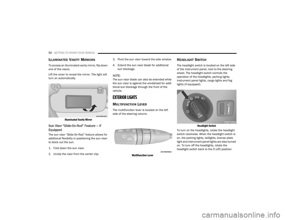
ILLUMINATED VANITY MIRRORS
To access an illuminated vanity mirror, flip down
one of the visors.
Lift the cover to reveal the mirror. The light will
turn on automatically.
Illuminated Vanity Mirror
Sun Visor “Slide-On-Rod” Feature — If
Equipped
The sun visor “Slide-On-Rod” feature allows for
additional flexibility in positioning the sun visor
to block out the sun.
1. Fold down the sun visor.
2. Unclip the visor from the center clip. 3. Pivot the sun visor toward the side window.
4. Extend the sun visor blade for additional
sun blockage.
NOTE:
The sun visor blade can also be extended while
the sun visor is against the windshield for addi -
tional sun blockage through the front of the
vehicle.
EXTERIOR LIGHTS
MULTIFUNCTION LEVER
The multifunction lever is located on the left
side of the steering column.
Multifunction Lever
HEADLIGHT SWITCH
The headlight switch is located on the left side
of the instrument panel, next to the steering
wheel. The headlight switch controls the
operation of the headlights, parking lights,
instrument panel lights, cargo lights and fog
lights (if equipped).
Headlight Switch
To turn on the headlights, rotate the headlight
switch clockwise. When the headlight switch is
on, the parking lights, taillights, license plate
light and instrument panel lights are also turned
on. To turn off the headlights, rotate the
headlight switch back to the O (off) position.
20_WD_OM_EN_USC_t.book Page 50
Page 53 of 464
GETTING TO KNOW YOUR VEHICLE51
NOTE:
Your vehicle is equipped with plastic head -
light and fog light (if equipped) lenses that
are lighter and less susceptible to stone
breakage than glass lights. Plastic is not as
scratch resistant as glass and therefore
different lens cleaning procedures must be
followed.
To minimize the possibility of scratching the
lenses and reducing light output, avoid
wiping with a dry cloth. To remove road dirt,
wash with a mild soap solution followed by
rinsing.
DAYTIME RUNNING LIGHTS (DRLS) —
I
F EQUIPPED
The Daytime Running Lights (DRLs) come on
whenever the engine is running, and the
transmission is not in the PARK position. The lights will remain on until the ignition is
placed in the OFF or ACC position, or the parking
brake is engaged. The headlight switch must be
used for normal night time driving.
NOTE:
If allowed by law in the country in which the
vehicle was purchased, the Daytime Running
Lights can be turned on and off using the
Uconnect system, refer to “Uconnect
Settings” in “Multimedia” for further informa
-
tion.
On some vehicles, the Daytime Running
Lights may deactivate, or reduce intensity, on
one side of the vehicle (when a turn signal is
activated on that side), or on both sides of
the vehicle (when the hazard warning lights
are activated).
HIGH/LOW BEAM SWITCH
Push the multifunction lever toward the
instrument panel to switch the headlights to
high beams. Pulling the multifunction back
toward the steering wheel will turn the low
beams back on, or shut the high beams off.
AUTOMATIC HIGH BEAM — IF EQUIPPED
The Automatic High Beam Headlamp Control
system provides increased forward lighting at
night by automating high beam control through
the use of a digital camera mounted on the
inside rearview mirror. This camera detects
vehicle specific light and automatically switches
from high beams to low beams until the
approaching vehicle is out of view.
NOTE:
The Automatic High Beam Headlamp Control
can be turned on or off by selecting or dese -
lecting “Auto High Beam” within your Ucon -
nect settings, as well as turning the headlight
switch to the AUTO position. Refer to “Ucon -
nect Settings” in “Multimedia” for further
information.
Broken, muddy, or obstructed headlights and
taillights of vehicles in the field of view will
cause headlights to remain on longer (closer
to the vehicle). Also, dirt, film, and other
obstructions on the windshield or camera
lens will cause the system to function
improperly.
CAUTION!
Do not use abrasive cleaning components,
solvents, steel wool or other abrasive
materials to clean the lenses.
2
20_WD_OM_EN_USC_t.book Page 51
Page 54 of 464
52GETTING TO KNOW YOUR VEHICLE
If the windshield or Automatic High Beam
Headlamp Control mirror is replaced, the mirror
must be re-aimed to ensure proper
performance. See a local authorized dealer.
FLASH-TO-PASS
You can signal another vehicle with your
headlights by lightly pulling the multifunction
lever toward you. This will cause the high beam
headlights to turn on, and remain on, until the
lever is released.
AUTOMATIC HEADLIGHTS
This system automatically turns the headlights
on or off according to ambient light levels. To
turn the system on, rotate the headlight switch
counterclockwise to the AUTO position. When
the system is on, the headlight time delay
feature is also on. This means the headlights
will stay on for up to 90 seconds after you place
the ignition into the OFF position. The headlight
time delay can be programmed 0/30/60/
90 seconds.
Refer to “Uconnect Settings” in “Multimedia”
for further information.
To turn the automatic system off, move the
headlight switch out of the AUTO position. NOTE:
The engine must be running before the head
-
lights will come on in the automatic mode.
PARKING LIGHTS AND PANEL LIGHTS
To turn on the parking lights and instrument
panel lights, rotate the headlight switch
clockwise. To turn off the parking lights, rotate
the headlight switch back to the O (off) position.
HEADLIGHTS ON AUTOMATICALLY WITH
W
IPERS
If your vehicle is equipped with Automatic
Headlights, it also has this
customer-programmable feature. When your
headlights are in the automatic mode and the
engine is running, they will automatically turn
on when the wiper system is on. This feature is
programmable through the Uconnect system.
Refer to “Uconnect Settings” in “Multimedia”
for further information.
NOTE:
When your headlights come on during the
daytime, the vehicle will monitor outside bright -
ness and decide if the instrument panel needs
to be dimmed or not. Refer to “Interior Lights” in
this chapter for further information.
HEADLIGHT DELAY
To aid in your exit, your vehicle is equipped with
a headlight delay that will leave the headlights
on for approximately 90 seconds. This delay is
initiated when the ignition is placed in the OFF
position while the headlight switch is on, and
then the headlight switch is cycled off.
Headlight delay can be canceled by either
turning the headlight switch on then off, or by
placing the ignition in the ON position.
NOTE:
The headlight delay time is programmable
through the Uconnect System. Refer to “Ucon -
nect Settings” in “Multimedia” for further infor -
mation.
LIGHTS-ON REMINDER
If the headlights, parking lights, or cargo lights
are left on after the ignition is placed in the OFF
position, a chime will sound when the driver’s
door is opened.
20_WD_OM_EN_USC_t.book Page 52
Page 55 of 464

GETTING TO KNOW YOUR VEHICLE53
FOG LIGHTS — IF EQUIPPED
The fog lights are turned on by rotating the
headlight switch to the parking light or headlight
position and pushing in the headlight rotary
control.
Fog Light Operation
The fog lights will operate only when the parking
lights are on or when the vehicle headlights are
on low beam. An indicator light located in the
instrument cluster display will illuminate when
the fog lights are on. The fog lights will turn off
when the switch is pushed a second time, when
the headlight switch is rotated to the off
position, or the high beam is selected.
TURN SIGNALS
Move the multifunction lever up or down and
the arrows on each side of the instrument
cluster will flash to show proper operation of the
front and rear turn signal lights.
NOTE:
If either light remains on and does not flash, or
there is a very fast flash rate, check for a defec -
tive outside light bulb. If an indicator fails to
light when the lever is moved, it would suggest
that the indicator bulb is defective.
LANE CHANGE ASSIST — IF EQUIPPED
Tap the multifunction lever up or down once,
without moving beyond the detent, and the turn
signal (right or left) will flash three times then
automatically turn off.
BATTERY SAVER
To protect the life of your vehicle’s battery, load
shedding is provided for both the interior and
exterior lights.
If the ignition is placed in the OFF position and
any door is left ajar for 10 minutes or the
dimmer control is rotated all the way up to the
dome on position for 10 minutes, the interior
lights will automatically turn off.
NOTE:
Battery saver mode is canceled if the ignition is
in the ON position.
If the headlights remain on while the ignition is
placed in the OFF position, the exterior lights will
automatically turn off after eight minutes. If the
headlights are turned on and left on for eight
minutes while the ignition is in the OFF position,
the exterior lights will automatically turn off.
2
20_WD_OM_EN_USC_t.book Page 53
Page 57 of 464
GETTING TO KNOW YOUR VEHICLE55
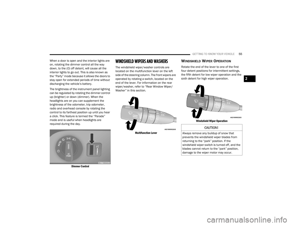
When a door is open and the interior lights are
on, rotating the dimmer control all the way
down, to the (O) off detent, will cause all the
interior lights to go out. This is also known as
the “Party” mode because it allows the doors to
stay open for extended periods of time without
discharging the vehicle’s battery.
The brightness of the instrument panel lighting
can be regulated by rotating the dimmer control
up (brighter) or down (dimmer). When the
headlights are on you can supplement the
brightness of the odometer, trip odometer,
radio and overhead console by rotating the
control to its farthest position up until you hear
a click. This feature is termed the “Parade”
mode and is useful when headlights are
required during the day.
Dimmer Control
WINDSHIELD WIPERS AND WASHERS
The windshield wiper/washer controls are
located on the multifunction lever on the left
side of the steering column. The front wipers are
operated by rotating a switch, located on the
end of the lever. For information on the rear
wiper/washer, refer to “Rear Window Wiper/
Washer” in this section.
Multifunction Lever
WINDSHIELD WIPER OPERATION
Rotate the end of the lever to one of the first
four detent positions for intermittent settings,
the fifth detent for low wiper operation and the
sixth detent for high wiper operation.
Windshield Wiper Operation
CAUTION!
Always remove any buildup of snow that
prevents the windshield wiper blades from
returning to the “park” position. If the
windshield wiper switch is turned off, and the
blades cannot return to the “park” position,
damage to the wiper motor may occur.
2
20_WD_OM_EN_USC_t.book Page 55
Page 120 of 464
118GETTING TO KNOW YOUR INSTRUMENT PANEL
LaneSense Indicator Light — If Equipped
The LaneSense indicator light
illuminates solid green when both
lane markings have been detected
and the system is “armed” and ready
to provide visual and torque warnings if an
unintentional lane departure occurs. Refer to
“LaneSense — If Equipped” in “Starting And
Operating” for further information.
Park/Headlight On Indicator Light
This indicator light will illuminate
when the park lights or headlights are
turned on. Refer to “Exterior Lights” in
“Getting To Know Your Vehicle” for
further information.
Snow Mode SRT Indicator Light
This light will turn on when Snow
Mode is active. Refer to the Drive
Modes Supplement for further
information.
Stop/Start Active Indicator Light — If
Equipped
This indicator light will illuminate
when the Stop/Start function is in
“Autostop” mode. Refer to “Stop /
Start System — If Equipped” in
“Starting And Operating” for further
information.
Sport Mode Indicator Light
This light will turn on when Sport
Mode is active. Refer to “Sport Mode
— If Equipped” in “Starting And
Operating” for further information.
Sport Mode SRT Indicator Light
This light will turn on when Sport
Mode is active. Refer to the Drive
Modes Supplement for further
information.
Tow Mode SRT Indicator Light
This light will turn on when Tow Mode
is active. Refer to the Drive Modes
Supplement for further information.
Track Mode SRT Indicator Light
This light will turn on when Track
Mode is active. Refer to the Drive
Modes Supplement for further
information.
Turn Signal Indicator Lights
When the left or right turn signal is
activated, the turn signal indicator will
flash independently and the
corresponding exterior turn signal
lamps will flash. Turn signals can be activated
when the multifunction lever is moved down
(left) or up (right).
NOTE:
A continuous chime will sound if the vehicle is
driven more than 1 mile (1.6 km) with either
turn signal on.
Check for an inoperative outside light bulb if
either indicator flashes at a rapid rate.
20_WD_OM_EN_USC_t.book Page 118
Page 121 of 464
GETTING TO KNOW YOUR INSTRUMENT PANEL119
WHITE INDICATOR LIGHTS
Adaptive Cruise Control (ACC) Ready Light
— If Equipped
This light will turn on when Adaptive
Cruise Control (ACC) has been turned
on, but is not set. Refer to “Adaptive
Cruise Control (ACC)” in “Starting And
Operating” for further information.
Custom Mode SRT Indicator Light
This light will turn on when Custom
Mode SRT is active. Refer to the Drive
Modes Supplement for further
information.
Cruise Control Ready Indicator
This indicator light will illuminate
when the cruise control is ready, but
not set. Refer to “Speed Control” in
“Starting And Operating” for further
information.
SRT Speed Warning Indicator Light — If
Equipped
When Set Speed Warning is turned
on, the speed warning telltale will
illuminate in the instrument cluster
with a number matching the set
speed. When the set speed is exceeded, the
indication will light up yellow and flash along
with a continuous chime. Speed Warning can be
turned on and off in the instrument cluster
display.
Refer to “Instrument Cluster Display” in this
chapter for further information.
The number “55” is only an example of a speed
that can be set.
LaneSense Indicator Light — If Equipped
When the LaneSense system is ON,
but not armed, the LaneSense
indicator light illuminates solid white.
This occurs when only left, right, or
neither lane line has been detected. If a single
lane line is detected, the system is ready to
provide only visual warnings if an unintentional
lane departure occurs on the detected lane line. Refer to “LaneSense — If Equipped” in “Starting
And Operating” for further information.
Valet Mode SRT Indicator Light
This light will turn on when Valet Mode
is active. Refer to the Drive Modes
Supplement for further information.
BLUE INDICATOR LIGHTS
High Beam Indicator Light
This indicator light will illuminate to
indicate that the high beam
headlights are on. With the low beams
activated, push the multifunction
lever forward (toward the front of the vehicle) to
turn on the high beams. Pull the multifunction
lever rearward (toward the rear of the vehicle) to
turn off the high beams. If the high beams are
off, pull the lever toward you for a temporary
high beam on, “flash to pass” scenario.
3
20_WD_OM_EN_USC_t.book Page 119
Page 163 of 464
SAFETY161
(Continued)
Enhanced Accident Response System
In the event of an impact, if the communication
network remains intact, and the power remains
intact, depending on the nature of the event,
the Occupant Restraint Controller (ORC) will
determine whether to have the Enhanced
Accident Response System perform the
following functions:
Cut off fuel to the engine (if equipped)
Cut off battery power to the electric motor (if
equipped)
Flash hazard lights as long as the battery has
power
Turn on the interior lights, which remain on
as long as the battery has power or for
15 minutes from the intervention of the
Enhanced Accident Response System
Unlock the power door locks
Your vehicle may also be designed to perform
any of these other functions in response to the
Enhanced Accident Response System:
Turn off the Fuel Filter Heater, Turn off the
HVAC Blower Motor, Close the HVAC Circula -
tion Door
Cut off battery power to the:
Engine
Electric Motor (if equipped)
Electric power steering
Brake booster
Electric park brake
Automatic transmission gear selector
Horn
Front wiper
Headlamp washer pump
NOTE:
After an accident, remember to cycle the igni -
tion to the STOP (OFF/LOCK) position and
remove the key from the ignition switch to avoid
draining the battery. Carefully check the vehicle
for fuel leaks in the engine compartment and on
the ground near the engine compartment and
fuel tank before resetting the system and
starting the engine. If there are no fuel leaks or
damage to the vehicle electrical devices (e.g.
headlights) after an accident, reset the system
by following the procedure described below. If you have any doubt, contact an authorized
dealer.
Enhanced Accident Response System
Reset Procedure
In order to reset the Enhanced Accident
Response System functions after an event, the
ignition switch must be changed from ignition
START or ON/RUN to ignition OFF. Carefully
check the vehicle for fuel leaks in the engine
compartment and on the ground near the
engine compartment and fuel tank before
resetting the system and starting the engine.
Maintaining Your Air Bag System
WARNING!
Modifications to any part of the air bag
system could cause it to fail when you need
it. You could be injured if the air bag system
is not there to protect you. Do not modify
the components or wiring, including adding
any kind of badges or stickers to the
steering wheel hub trim cover or the upper
passenger side of the instrument panel. Do
not modify the front bumper, vehicle body
structure, or add aftermarket side steps or
running boards.
4
20_WD_OM_EN_USC_t.book Page 161
Page 348 of 464
346SERVICING AND MAINTENANCE
STORING THE VEHICLE
If you are storing your vehicle for more than
21 days, we recommend that you take the
following steps to minimize the drain on your
vehicle's battery:
Disconnect the negative cable from battery.
Any time you store your vehicle or keep it out
of service (i.e., vacation) for two weeks or
more, run the air conditioning system at idle
for about five minutes in the fresh air and
high blower setting. This will ensure
adequate system lubrication to minimize the
possibility of compressor damage when the
system is started again.
BODYWORK
PROTECTION FROM ATMOSPHERIC
A
GENTS
Vehicle body care requirements vary according
to geographic locations and usage. Chemicals
that make roads passable in snow and ice and
those that are sprayed on trees and road
surfaces during other seasons are highly
corrosive to the metal in your vehicle. Outside parking, which exposes your vehicle to
airborne contaminants, road surfaces on which
the vehicle is operated, extreme hot or cold
weather and other extreme conditions will have
an adverse effect on paint, metal trim, and
underbody protection.
The following maintenance recommendations
will enable you to obtain maximum benefit from
the corrosion resistance built into your vehicle.
What Causes Corrosion?
Corrosion is the result of deterioration or
removal of paint and protective coatings from
your vehicle.
The most common causes are:
Road salt, dirt and moisture accumulation
Stone and gravel impact
Insects, tree sap and tar
Salt in the air near seacoast localities
Atmospheric fallout/industrial pollutants
BODY AND UNDERBODY MAINTENANCE
Cleaning Headlights
Your vehicle is equipped with plastic headlights
and fog lights that are lighter and less
susceptible to stone breakage than glass
headlights.
Plastic is not as scratch resistant as glass and
therefore different lens cleaning procedures
must be followed.
To minimize the possibility of scratching the
lenses and reducing light output, avoid wiping
with a dry cloth. To remove road dirt, wash with
a mild soap solution followed by rinsing.
Do not use abrasive cleaning components,
solvents, steel wool or other aggressive
material to clean the lenses.
20_WD_OM_EN_USC_t.book Page 346