sport mode DODGE DURANGO 2020 Owners Manual
[x] Cancel search | Manufacturer: DODGE, Model Year: 2020, Model line: DURANGO, Model: DODGE DURANGO 2020Pages: 464, PDF Size: 22.14 MB
Page 6 of 464
4
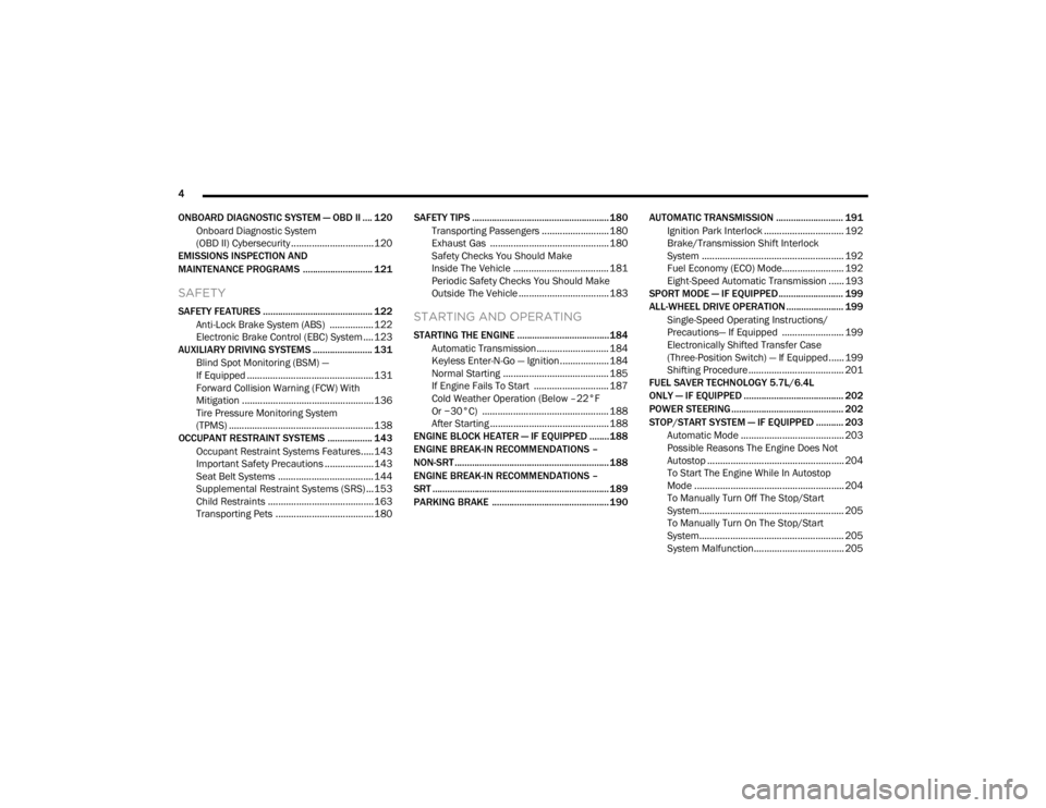
ONBOARD DIAGNOSTIC SYSTEM — OBD II .... 120 Onboard Diagnostic System
(OBD II) Cybersecurity ................................120
EMISSIONS INSPECTION AND
MAINTENANCE PROGRAMS ............................ 121
SAFETY
SAFETY FEATURES ............................................ 122
Anti-Lock Brake System (ABS) ................. 122
Electronic Brake Control (EBC) System ....123
AUXILIARY DRIVING SYSTEMS ........................ 131
Blind Spot Monitoring (BSM) —
If Equipped .................................................131 Forward Collision Warning (FCW) With
Mitigation ...................................................136 Tire Pressure Monitoring System
(TPMS) ........................................................ 138
OCCUPANT RESTRAINT SYSTEMS .................. 143
Occupant Restraint Systems Features.....143
Important Safety Precautions ...................143Seat Belt Systems ..................................... 144Supplemental Restraint Systems (SRS) ...153Child Restraints .........................................163
Transporting Pets ......................................180 SAFETY TIPS ....................................................... 180
Transporting Passengers .......................... 180Exhaust Gas .............................................. 180
Safety Checks You Should Make
Inside The Vehicle ..................................... 181 Periodic Safety Checks You Should Make
Outside The Vehicle ................................... 183STARTING AND OPERATING
STARTING THE ENGINE .....................................184
Automatic Transmission............................ 184
Keyless Enter-N-Go — Ignition ................... 184
Normal Starting ......................................... 185
If Engine Fails To Start ............................. 187Cold Weather Operation (Below –22°F
Or −30°C) ................................................. 188 After Starting .............................................. 188
ENGINE BLOCK HEATER — IF EQUIPPED ........188
ENGINE BREAK-IN RECOMMENDATIONS –
NON-SRT .............................................................. 188
ENGINE BREAK-IN RECOMMENDATIONS –
SRT ....................................................................... 189
PARKING BRAKE ............................................... 190 AUTOMATIC TRANSMISSION ........................... 191
Ignition Park Interlock ............................... 192Brake/Transmission Shift Interlock
System ....................................................... 192 Fuel Economy (ECO) Mode........................ 192
Eight-Speed Automatic Transmission ...... 193
SPORT MODE — IF EQUIPPED.......................... 199
ALL-WHEEL DRIVE OPERATION ....................... 199
Single-Speed Operating Instructions/
Precautions— If Equipped ........................ 199 Electronically Shifted Transfer Case
(Three-Position Switch) — If Equipped...... 199 Shifting Procedure ..................................... 201
FUEL SAVER TECHNOLOGY 5.7L/6.4L
ONLY — IF EQUIPPED ........................................ 202
POWER STEERING............................................. 202
STOP/START SYSTEM — IF EQUIPPED ........... 203 Automatic Mode ........................................ 203
Possible Reasons The Engine Does Not
Autostop ..................................................... 204 To Start The Engine While In Autostop
Mode .......................................................... 204 To Manually Turn Off The Stop/Start
System........................................................ 205 To Manually Turn On The Stop/Start
System........................................................ 205 System Malfunction................................... 205
20_WD_OM_EN_USC_t.book Page 4
Page 9 of 464
7
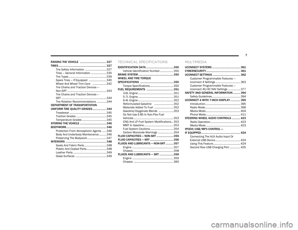
RAISING THE VEHICLE ..................................... 327
TIRES ................................................................... 327 Tire Safety Information .............................327Tires — General Information .....................335Tire Types ...................................................339
Spare Tires — If Equipped ........................ 340Wheel And Wheel Trim Care ...................342Tire Chains and Traction Devices —
Non-SRT .....................................................343 Tire Chains and Traction Devices —
SRT .............................................................344 Tire Rotation Recommendations .............344
DEPARTMENT OF TRANSPORTATION
UNIFORM TIRE QUALITY GRADES ................... 344
Treadwear .................................................. 345Traction Grades .........................................345
Temperature Grades .................................345
STORING THE VEHICLE ..................................... 346
BODYWORK ........................................................ 346
Protection From Atmospheric Agents ......346Body And Underbody Maintenance ..........346
Preserving The Bodywork ..........................347
INTERIORS ......................................................... 348
Seats And Fabric Parts .............................. 348
Plastic And Coated Parts ...........................348
Leather Parts .............................................349Glass Surfaces ..........................................349
TECHNICAL SPECIFICATIONS
IDENTIFICATION DATA .......................................350
Vehicle Identification Number .................. 350
BRAKE SYSTEM .................................................. 350
WHEEL AND TIRE TORQUE
SPECIFICATIONS ............................................... 350
Torque Specifications ................................ 350
FUEL REQUIREMENTS ......................................351
3.6L Engine ................................................ 351
5.7L Engine ................................................ 351
6.4L Engine ................................................ 352
Reformulated Gasoline .......................... 352Materials Added To Fuel .......................... 352Gasoline/Oxygenate Blends .................... 353
Do Not Use E-85 In Non-Flex Fuel
Vehicles ...................................................... 353 CNG And LP Fuel System Modifications... 353
MMT In Gasoline ........................................ 353
Fuel System Cautions................................ 354
Carbon Monoxide Warnings ..................... 354
FLUID CAPACITIES — NON-SRT ........................355
FLUID CAPACITIES — SRT ................................. 356
FLUIDS AND LUBRICANTS — NON-SRT ........... 357
Engine ........................................................ 357
Chassis ....................................................... 358
FLUIDS AND LUBRICANTS — SRT .................... 359
Engine ........................................................ 359
Chassis ...................................................... 360
MULTIMEDIA
UCONNECT SYSTEMS ........................................ 361
CYBERSECURITY ................................................ 361
UCONNECT SETTINGS ....................................... 362Customer Programmable Features —
Uconnect 4 Settings .................................. 363 Customer Programmable Features —
Uconnect 4C/4C NAV Settings ................. 377
SAFETY AND GENERAL INFORMATION .......... 394
Safety Guidelines....................................... 394
UCONNECT 4 WITH 7-INCH DISPLAY .............. 395
Introduction................................................ 395
Radio Mode ................................................ 396
Media Mode ............................................... 404
Phone Mode............................................... 411
STEERING WHEEL AUDIO CONTROLS ............ 423
Radio Operation......................................... 423Media Mode ............................................... 423
IPOD®/USB/MP3 CONTROL —
IF EQUIPPED ....................................................... 424
Connecting The AUX Audio Input Or
External USB Device .................................. 424 Using This Feature..................................... 424
Second Row USB Charging Port ............... 425
20_WD_OM_EN_USC_t.book Page 7
Page 96 of 464
94GETTING TO KNOW YOUR VEHICLE
(Continued)
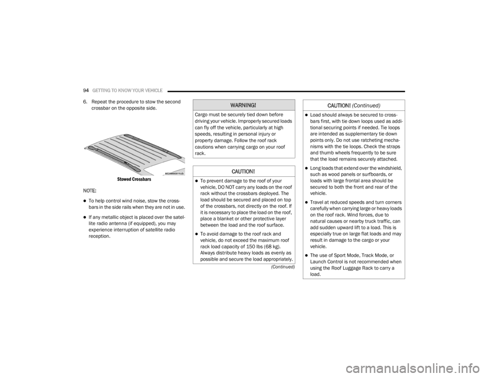
6. Repeat the procedure to stow the second crossbar on the opposite side.
Stowed Crossbars
NOTE:
To help control wind noise, stow the cross -
bars in the side rails when they are not in use.
If any metallic object is placed over the satel -
lite radio antenna (if equipped), you may
experience interruption of satellite radio
reception.
WARNING!
Cargo must be securely tied down before
driving your vehicle. Improperly secured loads
can fly off the vehicle, particularly at high
speeds, resulting in personal injury or
property damage. Follow the roof rack
cautions when carrying cargo on your roof
rack.
CAUTION!
To prevent damage to the roof of your
vehicle, DO NOT carry any loads on the roof
rack without the crossbars deployed. The
load should be secured and placed on top
of the crossbars, not directly on the roof. If
it is necessary to place the load on the roof,
place a blanket or other protective layer
between the load and the roof surface.
To avoid damage to the roof rack and
vehicle, do not exceed the maximum roof
rack load capacity of 150 lbs (68 kg).
Always distribute heavy loads as evenly as
possible and secure the load appropriately.
Load should always be secured to cross -
bars first, with tie down loops used as addi -
tional securing points if needed. Tie loops
are intended as supplementary tie down
points only. Do not use ratcheting mecha -
nisms with the tie loops. Check the straps
and thumb wheels frequently to be sure
that the load remains securely attached.
Long loads that extend over the windshield,
such as wood panels or surfboards, or
loads with large frontal area should be
secured to both the front and rear of the
vehicle.
Travel at reduced speeds and turn corners
carefully when carrying large or heavy loads
on the roof rack. Wind forces, due to
natural causes or nearby truck traffic, can
add sudden upward lift to a load. This is
especially true on large flat loads and may
result in damage to the cargo or your
vehicle.
The use of Sport Mode, Track Mode, or
Launch Control is not recommended when
using the Roof Luggage Rack to carry a
load.
CAUTION! (Continued)
20_WD_OM_EN_USC_t.book Page 94
Page 116 of 464
114GETTING TO KNOW YOUR INSTRUMENT PANEL
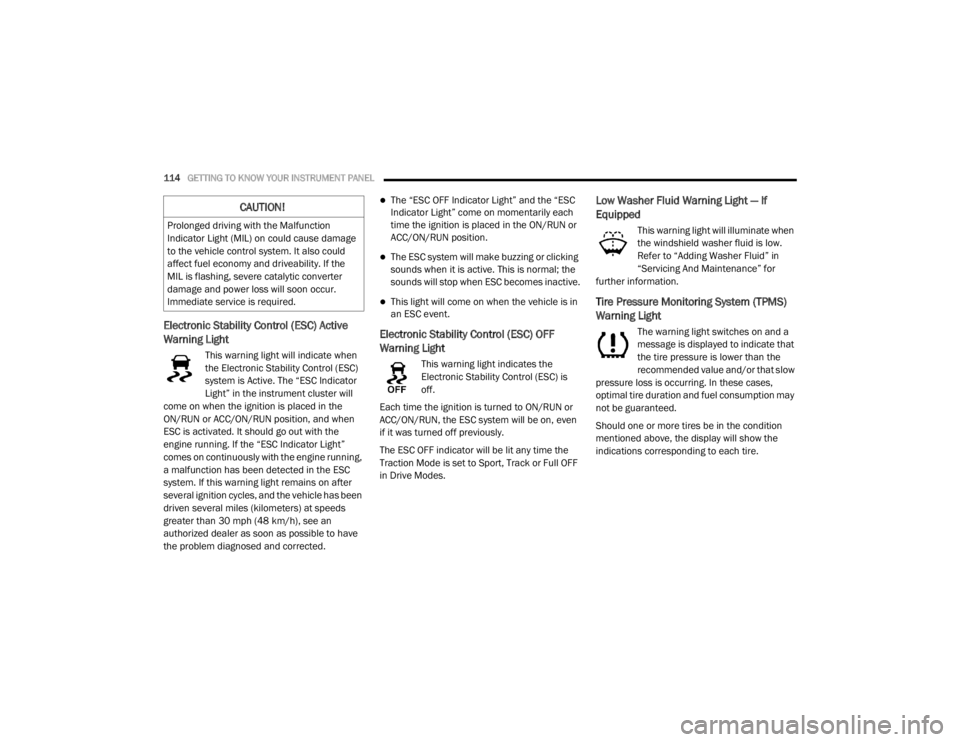
Electronic Stability Control (ESC) Active
Warning Light
This warning light will indicate when
the Electronic Stability Control (ESC)
system is Active. The “ESC Indicator
Light” in the instrument cluster will
come on when the ignition is placed in the
ON/RUN or ACC/ON/RUN position, and when
ESC is activated. It should go out with the
engine running. If the “ESC Indicator Light”
comes on continuously with the engine running,
a malfunction has been detected in the ESC
system. If this warning light remains on after
several ignition cycles, and the vehicle has been
driven several miles (kilometers) at speeds
greater than 30 mph (48 km/h), see an
authorized dealer as soon as possible to have
the problem diagnosed and corrected.
The “ESC OFF Indicator Light” and the “ESC
Indicator Light” come on momentarily each
time the ignition is placed in the ON/RUN or
ACC/ON/RUN position.
The ESC system will make buzzing or clicking
sounds when it is active. This is normal; the
sounds will stop when ESC becomes inactive.
This light will come on when the vehicle is in
an ESC event.
Electronic Stability Control (ESC) OFF
Warning Light
This warning light indicates the
Electronic Stability Control (ESC) is
off.
Each time the ignition is turned to ON/RUN or
ACC/ON/RUN, the ESC system will be on, even
if it was turned off previously.
The ESC OFF indicator will be lit any time the
Traction Mode is set to Sport, Track or Full OFF
in Drive Modes.
Low Washer Fluid Warning Light — If
Equipped
This warning light will illuminate when
the windshield washer fluid is low.
Refer to “Adding Washer Fluid” in
“Servicing And Maintenance” for
further information.
Tire Pressure Monitoring System (TPMS)
Warning Light
The warning light switches on and a
message is displayed to indicate that
the tire pressure is lower than the
recommended value and/or that slow
pressure loss is occurring. In these cases,
optimal tire duration and fuel consumption may
not be guaranteed.
Should one or more tires be in the condition
mentioned above, the display will show the
indications corresponding to each tire.
CAUTION!
Prolonged driving with the Malfunction
Indicator Light (MIL) on could cause damage
to the vehicle control system. It also could
affect fuel economy and driveability. If the
MIL is flashing, severe catalytic converter
damage and power loss will soon occur.
Immediate service is required.
20_WD_OM_EN_USC_t.book Page 114
Page 120 of 464
118GETTING TO KNOW YOUR INSTRUMENT PANEL
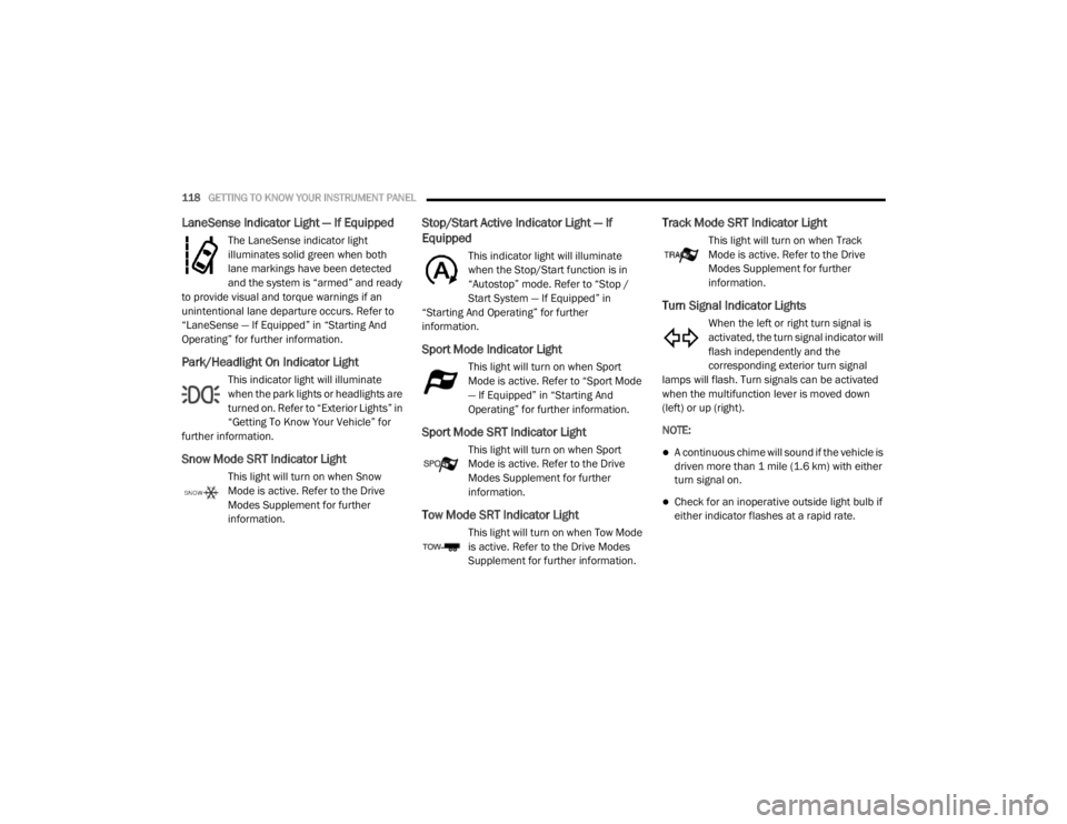
LaneSense Indicator Light — If Equipped
The LaneSense indicator light
illuminates solid green when both
lane markings have been detected
and the system is “armed” and ready
to provide visual and torque warnings if an
unintentional lane departure occurs. Refer to
“LaneSense — If Equipped” in “Starting And
Operating” for further information.
Park/Headlight On Indicator Light
This indicator light will illuminate
when the park lights or headlights are
turned on. Refer to “Exterior Lights” in
“Getting To Know Your Vehicle” for
further information.
Snow Mode SRT Indicator Light
This light will turn on when Snow
Mode is active. Refer to the Drive
Modes Supplement for further
information.
Stop/Start Active Indicator Light — If
Equipped
This indicator light will illuminate
when the Stop/Start function is in
“Autostop” mode. Refer to “Stop /
Start System — If Equipped” in
“Starting And Operating” for further
information.
Sport Mode Indicator Light
This light will turn on when Sport
Mode is active. Refer to “Sport Mode
— If Equipped” in “Starting And
Operating” for further information.
Sport Mode SRT Indicator Light
This light will turn on when Sport
Mode is active. Refer to the Drive
Modes Supplement for further
information.
Tow Mode SRT Indicator Light
This light will turn on when Tow Mode
is active. Refer to the Drive Modes
Supplement for further information.
Track Mode SRT Indicator Light
This light will turn on when Track
Mode is active. Refer to the Drive
Modes Supplement for further
information.
Turn Signal Indicator Lights
When the left or right turn signal is
activated, the turn signal indicator will
flash independently and the
corresponding exterior turn signal
lamps will flash. Turn signals can be activated
when the multifunction lever is moved down
(left) or up (right).
NOTE:
A continuous chime will sound if the vehicle is
driven more than 1 mile (1.6 km) with either
turn signal on.
Check for an inoperative outside light bulb if
either indicator flashes at a rapid rate.
20_WD_OM_EN_USC_t.book Page 118
Page 153 of 464
SAFETY151
(Continued)
In Automatic Locking Mode, the shoulder belt is
automatically pre-locked. The seat belt will still
retract to remove any slack in the shoulder belt.
Use the Automatic Locking Mode anytime a
child restraint is installed in a seating position
that has a seat belt with this feature. Children
12 years old and under should always be
properly restrained in the rear seat of a vehicle
with a rear seat. How To Engage The Automatic Locking Mode
1. Buckle the combination lap and shoulder
belt.
2. Grasp the shoulder portion and pull downward until the entire seat belt is
extracted.
3. Allow the seat belt to retract. As the seat belt retracts, you will hear a clicking sound.
This indicates the seat belt is now in the
Automatic Locking Mode.
How To Disengage The Automatic Locking Mode
Unbuckle the combination lap/shoulder belt
and allow it to retract completely to disengage
the Automatic Locking Mode and activate the
vehicle sensitive (emergency) locking mode.
Supplemental Active Head Restraints
(AHR)
These head restraints are passive, deployable
components, and vehicles with this equipment
cannot be readily identified by any markings,
only through visual inspection of the head
restraint. The head restraint will be split in two
halves, with the front half being soft foam and
trim, the back half being decorative plastic.
WARNING!
Never place a rear-facing child restraint in
front of an air bag. A deploying passenger
front air bag can cause death or serious
injury to a child 12 years or younger,
including a child in a rear-facing child
restraint.
Never install a rear-facing child restraint in
the front seat of a vehicle. Only use a
rear-facing child restraint in the rear seat. If
the vehicle does not have a rear seat, do
not transport a rear-facing child restraint in
that vehicle.
WARNING!
The seat belt assembly must be replaced if
the switchable Automatic Locking Retractor
(ALR) feature or any other seat belt function
is not working properly when checked
according to the procedures in the Service
Manual.
Failure to replace the seat belt assembly
could increase the risk of injury in colli -
sions.
Do not use the Automatic Locking Mode to
restrain occupants who are wearing the
seat belt or children who are using booster
seats. The locked mode is only used to
install rear-facing or forward-facing child
restraints that have a harness for
restraining the child.
WARNING! (Continued)
4
20_WD_OM_EN_USC_t.book Page 151
Page 182 of 464
180SAFETY
(Continued)
(Continued)
TRANSPORTING PETS
Air Bags deploying in the front seat could harm
your pet. An unrestrained pet will be thrown
about and possibly injured, or injure a
passenger during panic braking or in a collision.
Pets should be restrained in the rear seat (if
equipped) in pet harnesses or pet carriers that
are secured by seat belts.
SAFETY TIPS
TRANSPORTING PASSENGERS
NEVER TRANSPORT PASSENGERS IN THE
CARGO AREA.
EXHAUST GAS
WARNING!
The top tether anchorages are not visible
until the gap panel is folded down. Do not
use the visible cargo tie down hooks,
located on the floor behind the seats, to
attach a child restraint tether anchor.
An incorrectly anchored tether strap could
lead to increased head motion and
possible injury to the child. Use only the
anchorage position directly behind the child
seat to secure a child restraint top tether
strap.
If your vehicle is equipped with a split rear
seat, make sure the tether strap does not
slip into the opening between the seat
-
backs as you remove slack in the strap.
WARNING!
Do not leave children or animals inside
parked vehicles in hot weather. Interior
heat build-up may cause serious injury or
death.
It is extremely dangerous to ride in a cargo
area, inside or outside of a vehicle. In a
collision, people riding in these areas are
more likely to be seriously injured or killed.
Do not allow people to ride in any area of
your vehicle that is not equipped with seats
and seat belts.
Be sure everyone in your vehicle is in a seat
and using a seat belt properly.
WARNING!
Exhaust gases can injure or kill. They contain
carbon monoxide (CO), which is colorless and
odorless. Breathing it can make you
unconscious and can eventually poison you.
To avoid breathing (CO), follow these safety
tips:
Do not run the engine in a closed garage or
in confined areas any longer than needed
to move your vehicle in or out of the area.
If you are required to drive with the trunk/
liftgate/rear doors open, make sure that all
windows are closed and the climate control
BLOWER switch is set at high speed. DO
NOT use the recirculation mode.
WARNING! (Continued)
20_WD_OM_EN_USC_t.book Page 180
Page 191 of 464
STARTING AND OPERATING189
ENGINE BREAK-IN RECOMMENDATIONS –
SRT
The following tips will be helpful in obtaining
optimum performance and maximum durability
for your new SRT Vehicle.
Despite modern technology and World Class
manufacturing methods, the moving parts of
the vehicle still require wear in with one
another. This wearing in occurs mainly during
the first 500 miles (805 km) and continues
through the first oil change interval.
It is recommended that the operator observe
the following driving behaviors during the new
vehicle break-in period:
0 to 100 miles (0 to 161 km):
Do not allow the engine to operate at idle for
an extended period of time.
Depress the accelerator pedal slowly and
not more than halfway to avoid rapid
acceleration.
Avoid aggressive braking.
Drive with the engine speed less than
3,500 RPM.
Maintain vehicle speed below 55 mph
(88 km/h) and observe local speed limits.
100 to 300 miles (161 to 483 km):
Depress the accelerator pedal slowly and not
more than halfway to avoid rapid accelera -
tion in lower gears (FIRST to THIRD gears).
Avoid aggressive braking.
Drive with the engine speed less than
5,000 RPM.
Maintain vehicle speed below 70 mph
(112 km/h) and observe local speed limits. 300 to 500 miles (483 to 805 km):
Exercise the full engine RPM range, shifting
manually (paddles or gear shift) at higher
RPM when possible.
Do not perform sustained operation with the
accelerator pedal at wide open throttle.
Maintain vehicle speed below 85 mph
(136 km/h) and observe local speed limits.
For the first 1,500 miles (2,414 km):
Do not participate in track events, sport
driving schools, or similar activities during
the first 1,500 miles (2,414 km).
NOTE:
Check engine oil with every refueling and add if
necessary. Oil and fuel consumption may be
higher through the first oil change interval.
Running the engine with an oil level below the
add mark can cause severe engine damage.5
20_WD_OM_EN_USC_t.book Page 189
Page 201 of 464
STARTING AND OPERATING199
SPORT MODE — IF EQUIPPED
Your vehicle is equipped with a Sport Mode
feature. This mode is a configuration set up for
typical enthusiast driving. The engine,
transmission, and steering systems are all set
to their SPORT settings. Sport Mode will provide
improved throttle response and modified
transmission shift points for an enhanced
driving experience, as well as greater amount of
steering feel. This mode may be activated and
deactivated by pushing the Sport button on the
instrument panel switch bank.
ALL-WHEEL DRIVE OPERATION
SINGLE-SPEED OPERATING
I
NSTRUCTIONS/PRECAUTIONS— IF
E
QUIPPED
This system contains a single-speed (HI range
only) transfer case, which provides convenient
full-time All-Wheel Drive (AWD). No driver
interaction is required. The Brake Traction
Control (BTC) System, which combines standard
ABS and Traction Control, provides resistance
to any wheel that is slipping to allow additional
torque transfer to wheels with traction. NOTE:
This system is not appropriate for conditions
where LOW range is recommended. Refer to
“Driving Tips” in this chapter for further informa-
tion.
ELECTRONICALLY SHIFTED TRANSFER
C
ASE (THREE-POSITION SWITCH) — IF
E
QUIPPED
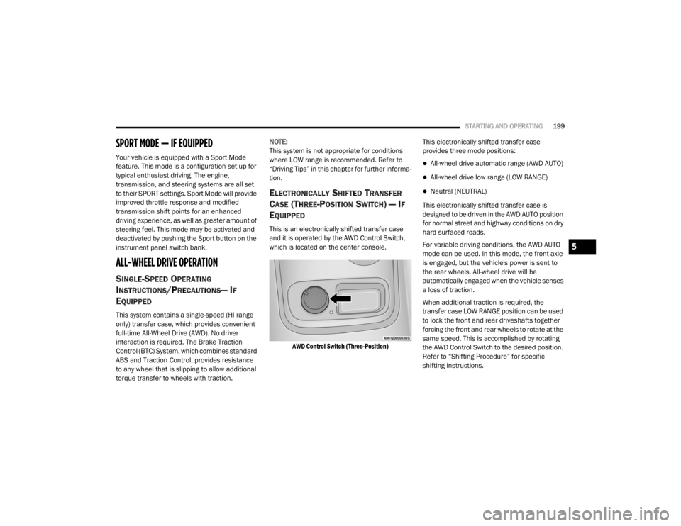
This is an electronically shifted transfer case
and it is operated by the AWD Control Switch,
which is located on the center console.
AWD Control Switch (Three-Position)
This electronically shifted transfer case
provides three mode positions:
All-wheel drive automatic range (AWD AUTO)
All-wheel drive low range (LOW RANGE)
Neutral (NEUTRAL)
This electronically shifted transfer case is
designed to be driven in the AWD AUTO position
for normal street and highway conditions on dry
hard surfaced roads.
For variable driving conditions, the AWD AUTO
mode can be used. In this mode, the front axle
is engaged, but the vehicle's power is sent to
the rear wheels. All-wheel drive will be
automatically engaged when the vehicle senses
a loss of traction.
When additional traction is required, the
transfer case LOW RANGE position can be used
to lock the front and rear driveshafts together
forcing the front and rear wheels to rotate at the
same speed. This is accomplished by rotating
the AWD Control Switch to the desired position.
Refer to “Shifting Procedure” for specific
shifting instructions.
5
20_WD_OM_EN_USC_t.book Page 199
Page 259 of 464
STARTING AND OPERATING257
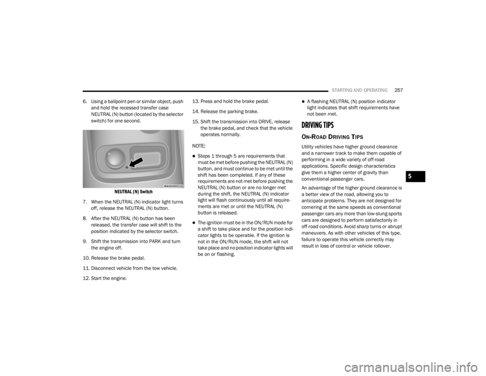
6. Using a ballpoint pen or similar object, push
and hold the recessed transfer case
NEUTRAL (N) button (located by the selector
switch) for one second.
NEUTRAL (N) Switch
7. When the NEUTRAL (N) indicator light turns off, release the NEUTRAL (N) button.
8. After the NEUTRAL (N) button has been released, the transfer case will shift to the
position indicated by the selector switch.
9. Shift the transmission into PARK and turn the engine off.
10. Release the brake pedal.
11. Disconnect vehicle from the tow vehicle.
12. Start the engine. 13. Press and hold the brake pedal.
14. Release the parking brake.
15. Shift the transmission into DRIVE, release
the brake pedal, and check that the vehicle
operates normally.
NOTE:
Steps 1 through 5 are requirements that
must be met before pushing the NEUTRAL (N)
button, and must continue to be met until the
shift has been completed. If any of these
requirements are not met before pushing the
NEUTRAL (N) button or are no longer met
during the shift, the NEUTRAL (N) indicator
light will flash continuously until all require -
ments are met or until the NEUTRAL (N)
button is released.
The ignition must be in the ON/RUN mode for
a shift to take place and for the position indi -
cator lights to be operable. If the ignition is
not in the ON/RUN mode, the shift will not
take place and no position indicator lights will
be on or flashing.
A flashing NEUTRAL (N) position indicator
light indicates that shift requirements have
not been met.
DRIVING TIPS
ON-ROAD DRIVING TIPS
Utility vehicles have higher ground clearance
and a narrower track to make them capable of
performing in a wide variety of off-road
applications. Specific design characteristics
give them a higher center of gravity than
conventional passenger cars.
An advantage of the higher ground clearance is
a better view of the road, allowing you to
anticipate problems. They are not designed for
cornering at the same speeds as conventional
passenger cars any more than low-slung sports
cars are designed to perform satisfactorily in
off-road conditions. Avoid sharp turns or abrupt
maneuvers. As with other vehicles of this type,
failure to operate this vehicle correctly may
result in loss of control or vehicle rollover.
5
20_WD_OM_EN_USC_t.book Page 257