ESP DODGE DURANGO 2021 Owner's Guide
[x] Cancel search | Manufacturer: DODGE, Model Year: 2021, Model line: DURANGO, Model: DODGE DURANGO 2021Pages: 340, PDF Size: 20.38 MB
Page 245 of 340
243
IN CASE OF EMERGENCY
HAZARD WARNING FLASHERS
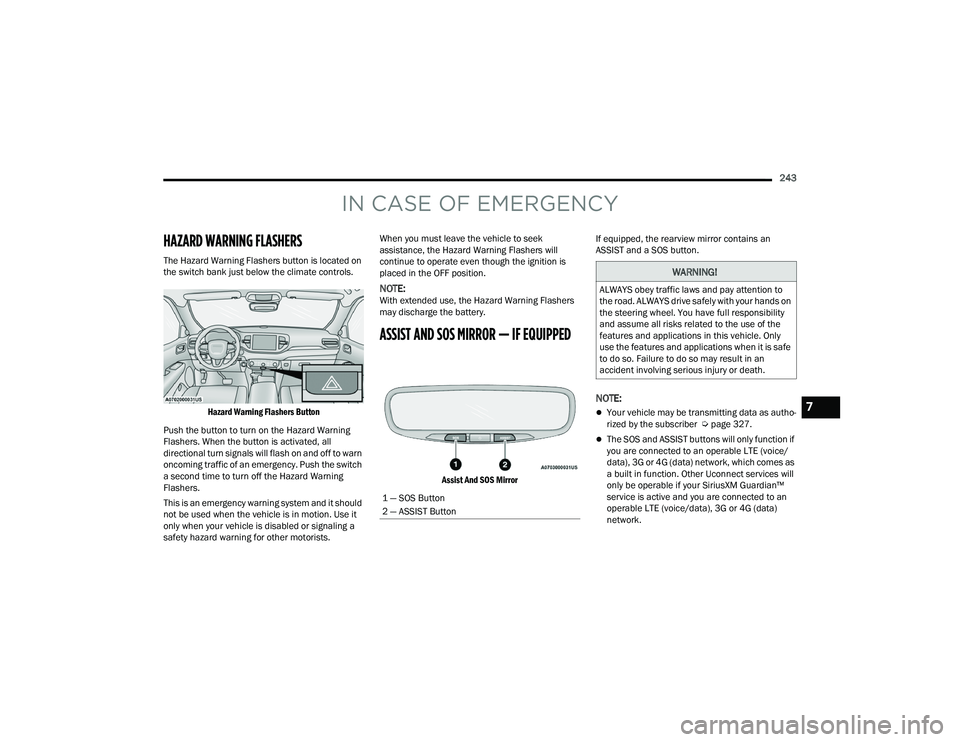
The Hazard Warning Flashers button is located on
the switch bank just below the climate controls.
Hazard Warning Flashers Button
Push the button to turn on the Hazard Warning
Flashers. When the button is activated, all
directional turn signals will flash on and off to warn
oncoming traffic of an emergency. Push the switch
a second time to turn off the Hazard Warning
Flashers.
This is an emergency warning system and it should
not be used when the vehicle is in motion. Use it
only when your vehicle is disabled or signaling a
safety hazard warning for other motorists. When you must leave the vehicle to seek
assistance, the Hazard Warning Flashers will
continue to operate even though the ignition is
placed in the OFF position.
NOTE:With extended use, the Hazard Warning Flashers
may discharge the battery.
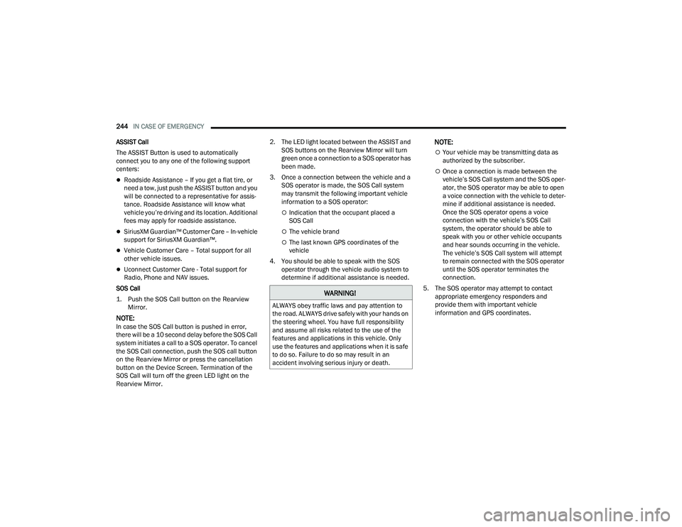
ASSIST AND SOS MIRROR — IF EQUIPPED
Assist And SOS Mirror
If equipped, the rearview mirror contains an
ASSIST and a SOS button.
NOTE:
Your vehicle may be transmitting data as autho
-
rized by the subscriber Ú page 327.
The SOS and ASSIST buttons will only function if
you are connected to an operable LTE (voice/
data), 3G or 4G (data) network, which comes as
a built in function. Other Uconnect services will
only be operable if your SiriusXM Guardian™
service is active and you are connected to an
operable LTE (voice/data), 3G or 4G (data)
network.
1 — SOS Button
2 — ASSIST Button
WARNING!
ALWAYS obey traffic laws and pay attention to
the road. ALWAYS drive safely with your hands on
the steering wheel. You have full responsibility
and assume all risks related to the use of the
features and applications in this vehicle. Only
use the features and applications when it is safe
to do so. Failure to do so may result in an
accident involving serious injury or death.
7
21_WD_OM_EN_USC_t.book Page 243
Page 246 of 340
244IN CASE OF EMERGENCY
ASSIST Call
The ASSIST Button is used to automatically
connect you to any one of the following support
centers:
Roadside Assistance – If you get a flat tire, or
need a tow, just push the ASSIST button and you
will be connected to a representative for assis-
tance. Roadside Assistance will know what
vehicle you’re driving and its location. Additional
fees may apply for roadside assistance.
SiriusXM Guardian™ Customer Care – In-vehicle
support for SiriusXM Guardian™.
Vehicle Customer Care – Total support for all
other vehicle issues.
Uconnect Customer Care - Total support for
Radio, Phone and NAV issues.
SOS Call
1. Push the SOS Call button on the Rearview Mirror.
NOTE:In case the SOS Call button is pushed in error,
there will be a 10 second delay before the SOS Call
system initiates a call to a SOS operator. To cancel
the SOS Call connection, push the SOS call button
on the Rearview Mirror or press the cancellation
button on the Device Screen. Termination of the
SOS Call will turn off the green LED light on the
Rearview Mirror. 2. The LED light located between the ASSIST and
SOS buttons on the Rearview Mirror will turn
green once a connection to a SOS operator has
been made.
3. Once a connection between the vehicle and a SOS operator is made, the SOS Call system
may transmit the following important vehicle
information to a SOS operator:
Indication that the occupant placed a
SOS Call
The vehicle brand
The last known GPS coordinates of the
vehicle
4. You should be able to speak with the SOS operator through the vehicle audio system to
determine if additional assistance is needed.
NOTE:
Your vehicle may be transmitting data as
authorized by the subscriber.
Once a connection is made between the
vehicle’s SOS Call system and the SOS oper -
ator, the SOS operator may be able to open
a voice connection with the vehicle to deter -
mine if additional assistance is needed.
Once the SOS operator opens a voice
connection with the vehicle’s SOS Call
system, the operator should be able to
speak with you or other vehicle occupants
and hear sounds occurring in the vehicle.
The vehicle’s SOS Call system will attempt
to remain connected with the SOS operator
until the SOS operator terminates the
connection.
5. The SOS operator may attempt to contact appropriate emergency responders and
provide them with important vehicle
information and GPS coordinates.
WARNING!
ALWAYS obey traffic laws and pay attention to
the road. ALWAYS drive safely with your hands on
the steering wheel. You have full responsibility
and assume all risks related to the use of the
features and applications in this vehicle. Only
use the features and applications when it is safe
to do so. Failure to do so may result in an
accident involving serious injury or death.
21_WD_OM_EN_USC_t.book Page 244
Page 247 of 340
IN CASE OF EMERGENCY245
(Continued) SOS Call System Limitations
Vehicles sold in Mexico DO NOT have SOS Call
system capabilities.
SOS or other emergency line operators in Mexico
may not answer or respond to SOS system calls. If the SOS Call system detects a malfunction, any
of the following may occur at the time the
malfunction is detected, and at the beginning of
each ignition cycle:
The Rearview Mirror light located between the
ASSIST and SOS buttons will continuously illumi
-
nate red.
The Device Screen will display the following
message “Vehicle device requires service.
Please contact an authorized dealer.”
An In-Vehicle Audio message will state “Vehicle
device requires service. Please contact an
authorized dealer.”
WARNING!
If anyone in the vehicle could be in danger
(e.g., fire or smoke is visible, dangerous road
conditions or location), do not wait for voice
contact from an Emergency Services Agent. All
occupants should exit the vehicle immediately
and move to a safe location.
Never place anything on or near the vehicle’s
operable network and GPS antennas. You
could prevent operable network and GPS
signal reception, which can prevent your
vehicle from placing an emergency call. An
operable network and GPS signal reception is
required for the SOS Call system to function
properly.
The SOS Call system is embedded into the
vehicle’s electrical system. Do not add after -
market electrical equipment to the vehicle’s
electrical system. This may prevent your
vehicle from sending a signal to initiate an
emergency call. To avoid interference that can
cause the SOS Call system to fail, never add
aftermarket equipment (e.g., two-way mobile
radio, CB radio, data recorder, etc.) to your
vehicle’s electrical system or modify the
antennas on your vehicle. IF YOUR VEHICLE
LOSES BATTERY POWER FOR ANY REASON
(INCLUDING DURING OR AFTER AN ACCI -
DENT), THE UCONNECT FEATURES, APPS AND
SERVICES, AMONG OTHERS, WILL NOT
OPERATE.
Modifications to any part of the SOS Call
system could cause the air bag system to fail
when you need it. You could be injured if the
air bag system is not there to help protect you.
WARNING!
WARNING!
Ignoring the Rearview Mirror light could mean
you will not have SOS Call services. If the Rear -
view Mirror light is illuminated, have an autho -
rized dealer service the SOS Call system
immediately.
The Occupant Restraint Control module turns
on the air bag Warning Light on the instrument
panel if a malfunction in any part of the
system is detected. If the Air Bag Warning
Light is illuminated, have an authorized dealer
service the Occupant Restraint Control system
immediately.
7
21_WD_OM_EN_USC_t.book Page 245
Page 248 of 340
246IN CASE OF EMERGENCY
Even if the SOS Call system is fully functional,
factors beyond FCA US LLC’s control may prevent
or stop the SOS Call system operation. These
include, but are not limited to, the following
factors:
The ignition is in the OFF position
The vehicle’s electrical systems are not intact
The SOS Call system software and/or hardware
are damaged during a crash
The vehicle battery loses power or becomes
disconnected during a vehicle crash
LTE (voice/data), 3G or 4G (data) network and/
or Global Positioning Satellite signals are
unavailable or obstructed
Equipment malfunction at the SOS operator
facility
Operator error by the SOS operator
LTE (voice/data), 3G or 4G (data) network
congestion
Weather
Buildings, structures, geographic terrain, or
tunnels
NOTE:
Your vehicle may be transmitting data as autho -
rized by the subscriber.
Never place anything on or near the vehicle’s
LTE (voice/data), 3G or 4G (data) and GPS
antennas. You could prevent LTE (voice/data),
3G or 4G (data) and GPS signal reception, which
can prevent your vehicle from placing an emer -
gency call. An operable LTE (voice/data), 3G or
4G (data) network connection and a GPS signal
is required for the SOS Call system to function
properly.
NOTE:Changes or modifications not expressly approved
by the party responsible for compliance could void
the user's authority to operate the equipment.
Automatic SOS — If Equipped
Automatic SOS is a hands-free safety service that
can immediately connect you with help in the event
that your vehicle’s airbags deploy. Please refer to
your provided radio supplement for complete
information.WARNING!
ALWAYS obey traffic laws and pay attention to
the road. ALWAYS drive safely with your hands on
the steering wheel. You have full responsibility
and assume all risks related to the use of the
features and applications in this vehicle. Only
use the features and applications when it is safe
to do so. Failure to do so may result in an
accident involving serious injury or death.
CAUTION!
To avoid damage to the mirror during cleaning,
never spray any cleaning solution directly onto
the mirror. Apply the solution onto a clean cloth
and wipe the mirror clean.
21_WD_OM_EN_USC_t.book Page 246
Page 265 of 340
IN CASE OF EMERGENCY263
ALL WHEEL DRIVE MODELS
FCA US LLC recommends towing with all wheels
OFF the ground. Acceptable methods are to tow
the vehicle on a flatbed or with one end of the
vehicle raised and the opposite end on a
towing dolly.
If flatbed equipment is not available, and the
transfer case is operable, vehicles with a
two-speed transfer case may be towed (in the
forward direction, with ALL wheels on the ground),
IF the transfer case is in NEUTRAL (N) and the
transmission is in PARK Úpage 153. Vehicles equipped with a single-speed transfer
case have no NEUTRAL (N) position, and therefore
must
be towed will all four wheels OFF the ground.
ENHANCED ACCIDENT RESPONSE SYSTEM
(EARS)
This vehicle is equipped with an Enhanced
Accident Response System.
This feature is a communication network that
takes effect in the event of an impact Úpage 221.
EVENT DATA RECORDER (EDR)
This vehicle is equipped with an event data
recorder (EDR). The main purpose of an EDR is to
record data that will assist in understanding how a
vehicle’s systems performed under certain crash
or near crash-like situations, such as an air bag
deployment or hitting a road obstacle Úpage 222.
CAUTION!
Front or rear wheel lifts must not be used
(if the remaining wheels are on the ground).
Internal damage to the transmission or
transfer case will occur if a front or rear wheel
lift is used when towing.
Towing this vehicle in violation of the above
requirements can cause severe transmission
and/or transfer case damage. Damage from
improper towing is not covered under the New
Vehicle Limited Warranty.
7
21_WD_OM_EN_USC_t.book Page 263
Page 284 of 340
282SERVICING AND MAINTENANCE
Please review these recommendations for using
Organic Additive Technology (OAT) engine coolant
that meets the requirements of the manufacturer
Material Standard MS.90032. When adding
engine coolant:
We recommend using Mopar® Antifreeze/
Coolant 10 Year/150,000 Mile (240,000 km)
Formula OAT that meets the requirements of the
manufacturer Material Standard MS.90032.
Mix a minimum solution of 50% OAT engine
coolant that meets the requirements of the
manufacturer Material Standard MS.90032
and distilled water. Use higher concentrations
(not to exceed 70%) if temperatures below
−34°F (−37°C) are anticipated. Please contact
an authorized dealer for assistance.
Use only high purity water such as distilled or
deionized water when mixing the water/engine
coolant solution. The use of lower quality water
will reduce the amount of corrosion protection
in the engine cooling system.
NOTE:
It is the owner's responsibility to maintain the
proper level of protection against freezing
according to the temperatures occurring in the
area where the vehicle is operated.
Some vehicles require special tools to add
coolant properly. Failure to fill these systems
properly could lead to severe internal engine
damage. If any coolant is needed to be added to
the system, please contact a local authorized
dealer.
Mixing engine coolant types is not recom -
mended and can result in cooling system
damage. If HOAT and OAT coolant are mixed in
an emergency, have a authorized dealer drain,
flush, and refill with OAT coolant (conforming to
MS.90032) as soon as possible.
Cooling System Pressure Cap
The cap must be fully tightened to prevent loss of
engine coolant (antifreeze), and to ensure that
engine coolant will return to the radiator from the
coolant expansion bottle/recovery tank if so
equipped.
The cap should be inspected and cleaned if there
is any accumulation of foreign material on the
sealing surfaces.Disposal Of Used Coolant
Used ethylene glycol-based coolant (antifreeze) is
a regulated substance requiring proper disposal.
Check with your local authorities to determine the
disposal rules for your community. To prevent
ingestion by animals or children, do not store
ethylene glycol-based coolant in open containers
or allow it to remain in puddles on the ground,
clean up any ground spills immediately. If ingested,
seek emergency assistance immediately.
WARNING!
Do not open hot engine cooling system. Never
add engine coolant (antifreeze) when the
engine is overheated. Do not loosen or
remove the cap to cool an overheated engine.
Heat causes pressure to build up in the
cooling system. To prevent scalding or injury,
do not remove the pressure cap while the
system is hot or under pressure.
Do not use a pressure cap other than the one
specified for your vehicle. Personal injury or
engine damage may result.
21_WD_OM_EN_USC_t.book Page 282
Page 289 of 340
SERVICING AND MAINTENANCE287
Underhood Fuses
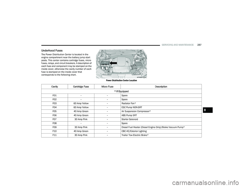
The Power Distribution Center is located in the
engine compartment near the battery jump start
posts. This center contains cartridge fuses, micro
fuses, relays, and circuit breakers. A description of
each fuse and component may be stamped on the
inside cover, otherwise the cavity number of each
fuse is stamped on the inside cover that
corresponds to the following chart.
Power Distribution Center Location
CavityCartridge Fuse Micro Fuse Description
* If Equipped
F01 ––Spare
F02 ––Spare
F03 60 Amp Yellow –Radiator Fan*
F04 60 Amp Yellow –ESC Pump NON-SRT
F05 40 Amp Green –Air Suspension Compressor*
F06 40 Amp Green –ABS Pump SRT
F07 30 Amp Pink –Starter Solenoid
F08 ––Spare
F09 30 Amp Pink –Diesel Fuel Heater (Diesel Engine Only)/Brake Vacuum Pump*
F10 40 Amp Green –CBC #2/Exterior Lighting
F11 30 Amp Pink –Trailer Tow Electric Brake*
8
21_WD_OM_EN_USC_t.book Page 287
Page 290 of 340
288SERVICING AND MAINTENANCE
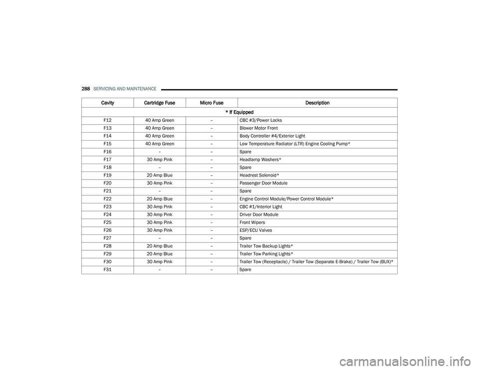
F12 40 Amp Green –CBC #3/Power Locks
F13 40 Amp Green –Blower Motor Front
F14 40 Amp Green –Body Controller #4/Exterior Light
F15 40 Amp Green –Low Temperature Radiator (LTR) Engine Cooling Pump*
F16 ––Spare
F17 30 Amp Pink –Headlamp Washers*
F18 ––Spare
F19 20 Amp Blue –Headrest Solenoid*
F20 30 Amp Pink –Passenger Door Module
F21 ––Spare
F22 20 Amp Blue –Engine Control Module/Power Control Module*
F23 30 Amp Pink –CBC #1/Interior Light
F24 30 Amp Pink –Driver Door Module
F25 30 Amp Pink –Front Wipers
F26 30 Amp Pink –ESP/ECU Valves
F27 ––Spare
F28 20 Amp Blue –Trailer Tow Backup Lights*
F29 20 Amp Blue –Trailer Tow Parking Lights*
F30 30 Amp Pink –Trailer Tow (Receptacle) / Trailer Tow (Separate E-Brake) / Trailer Tow (BUX)*
F31 ––Spare
Cavity Cartridge Fuse Micro Fuse Description
* If Equipped
21_WD_OM_EN_USC_t.book Page 288
Page 293 of 340
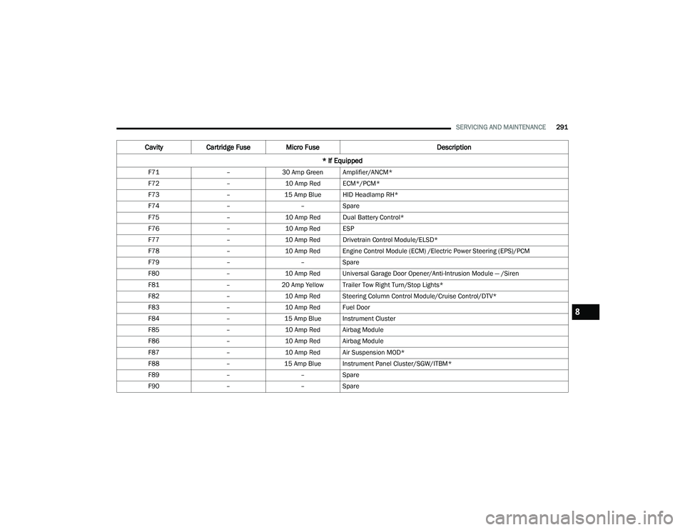
SERVICING AND MAINTENANCE291
F71 –30 Amp Green Amplifier/ANCM*
F72 –10 Amp Red ECM*/PCM*
F73 –15 Amp Blue HID Headlamp RH*
F74 ––Spare
F75 –10 Amp Red Dual Battery Control*
F76 –10 Amp Red ESP
F77 –10 Amp Red Drivetrain Control Module/ELSD*
F78 –10 Amp Red Engine Control Module (ECM) /Electric Power Steering (EPS)/PCM
F79 ––Spare
F80 –10 Amp Red Universal Garage Door Opener/Anti-Intrusion Module — /Siren
F81 –20 Amp Yellow Trailer Tow Right Turn/Stop Lights*
F82 –10 Amp Red Steering Column Control Module/Cruise Control/DTV*
F83 –10 Amp Red Fuel Door
F84 –15 Amp Blue Instrument Cluster
F85 –10 Amp Red Airbag Module
F86 –10 Amp Red Airbag Module
F87 –10 Amp Red Air Suspension MOD*
F88 –15 Amp Blue Instrument Panel Cluster/SGW/ITBM*
F89 ––Spare
F90 ––Spare
Cavity Cartridge Fuse Micro Fuse Description
* If Equipped
8
21_WD_OM_EN_USC_t.book Page 291
Page 299 of 340
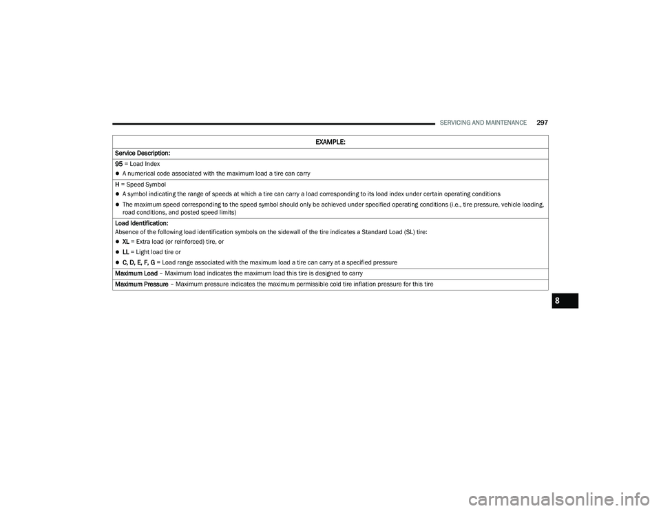
SERVICING AND MAINTENANCE297
Service Description:
95 = Load Index
A numerical code associated with the maximum load a tire can carry
H = Speed Symbol
A symbol indicating the range of speeds at which a tire can carry a load corresponding to its load index under certain operating conditions
The maximum speed corresponding to the speed symbol should only be achieved under specified operating conditions (i.e., tire pressure, vehicle loading,
road conditions, and posted speed limits)
Load Identification:
Absence of the following load identification symbols on the sidewall of the tire indicates a Standard Load (SL) tire:
XL = Extra load (or reinforced) tire, or
LL = Light load tire or
C, D, E, F, G = Load range associated with the maximum load a tire can carry at a specified pressure
Maximum Load – Maximum load indicates the maximum load this tire is designed to carry
Maximum Pressure – Maximum pressure indicates the maximum permissible cold tire inflation pressure for this tire
EXAMPLE:
8
21_WD_OM_EN_USC_t.book Page 297