change time DODGE DURANGO 2021 Owners Manual
[x] Cancel search | Manufacturer: DODGE, Model Year: 2021, Model line: DURANGO, Model: DODGE DURANGO 2021Pages: 340, PDF Size: 20.38 MB
Page 5 of 340
3
EXTERIOR LIGHTS.................................................. 48 Multifunction Lever ..........................................48
Headlight Switch ..............................................48
Daytime Running Lights (DRLs) ......................49
High/Low Beam Switch....................................49
Automatic High Beam — If Equipped ..............50
Flash-To-Pass ..................................................50
Automatic Headlights ......................................50
Parking Lights And Panel Lights ......................50
Automatic Headlights With Wipers..................50
Headlight Delay ................................................51
Lights-On Reminder..........................................51
Fog Lights — If Equipped ..................................51
Turn Signals ......................................................51
Lane Change Assist — If Equipped ..................51
Automatic Headlight Leveling —
If Equipped........................................................52
Battery Saver ....................................................52
INTERIOR LIGHTS ................................................. 52
Courtesy Lights .................................................52
WINDSHIELD WIPERS AND WASHERS .............. 53
Windshield Wiper Operation ...........................53
Rain Sensing Wipers — If Equipped ...............54
Rear Window Wiper/Washer ..........................55
CLIMATE CONTROLS ............................................. 55
Automatic Climate Control Descriptions And
Functions ..........................................................55
Automatic Temperature Control (ATC) ..........62
Climate Voice Recognition ...............................62
Operating Tips .................................................62 INTERIOR STORAGE AND EQUIPMENT ............... 64
Storage..............................................................64
USB/AUX Control .............................................67
Electrical Power Outlets .................................68
Power Inverter — If Equipped ..........................70
Wireless Charging Pad —
If Equipped .......................................................71
WINDOWS ..............................................................71
Power Windows ................................................71
Wind Buffeting .................................................73
POWER SUNROOF — IF EQUIPPED ...................... 73
Opening And Closing The Sunroof...................73
Sunshade Operation ........................................73
Pinch Protect Feature ......................................74
Venting Sunroof................................................74
Sunroof Maintenance ......................................74
Ignition Off Operation.......................................74
HOOD .......................................................................74
Opening The Hood............................................74
Closing The Hood .............................................75
LIFTGATE ................................................................. 75
Power Liftgate — If Equipped ...........................75
Cargo Area Features .......................................76
ROOF LUGGAGE RACK — IF EQUIPPED ............... 77
Deploying The Crossbars .................................78
Stowing The Crossbars ....................................80
GETTING TO KNOW YOUR
INSTRUMENT PANEL
INSTRUMENT CLUSTER ........................................ 82Instrument Cluster Descriptions ..................... 83
INSTRUMENT CLUSTER DISPLAY ........................ 83
Location And Controls...................................... 83
Engine Oil Life Reset ....................................... 85
Display And Messages ..................................... 86
Instrument Cluster Display Menu Items ........ 87
Battery Saver On/Battery Saver Mode
Message — Electrical Load Reduction
Actions — If Equipped ...................................... 89
WARNING LIGHTS AND MESSAGES ................... 91
Red Warning Lights ..........................................91
Yellow Warning Lights ...................................... 94
Yellow Indicator Lights ..................................... 97
Green Indicator Lights ..................................... 97
White Indicator Lights ...................................... 98
Blue Indicator Lights ........................................ 98
ONBOARD DIAGNOSTIC SYSTEM — OBD II ........ 99
Onboard Diagnostic System
(OBD II) Cybersecurity ...................................... 99
EMISSIONS INSPECTION AND MAINTENANCE
PROGRAMS .......................................................... 100
21_WD_OM_EN_USC_t.book Page 3
Page 10 of 340
8
INTRODUCTION
Dear Customer,
Congratulations on the purchase of your new Dodge vehicle. Be assured that it represents precision workmanship, distinctive styling, and high quality.
This is a specialized utility vehicle. It can go places and perform tasks that are not intended for conventional passenger vehicles. It handles and maneuvers
differently from many passenger vehicles both on-road and off-road, so take time to become familiar with your vehicle. If equipped, the two-wheel drive version
of this vehicle was designed for on-road use only. It is not intended for off-road driving or use in other severe conditions suited for a four-wheel drive vehicle.
Before you start to drive this vehicle, read the Owner’s Manual. Be sure you are familiar with all vehicle controls, particularly those used for braking, steering,
transmission, and transfer case shifting. Learn how your vehicle handles on different road surfaces. Your driving skills will improve with experience. When driving
off-road, or working the vehicle, don’t overload the vehicle or expect the vehicle to overcome the natural laws of physics. Always observe federal, state, provincial
and local laws wherever you drive. As with other vehicles of this type, failure to operate this vehicle correctly may result in loss of control or a collision Úpage 156.
This Owner's Manual has been prepared with the assistance of service and engineering specialists to acquaint you with the operation and maintenance of your
vehicle. It is supplemented by customer-oriented documents. Within this information, you will find a description of the services that FCA US LLC offers to its
customers as well as the details of the terms and conditions for maintaining its validity. Please take the time to read all of these publications carefully before
driving your vehicle for the first time. Following the instructions, recommendations, tips, and important warnings in this manual will help ensure safe and
enjoyable operation of your vehicle.
This Owner's Manual describes all versions of this vehicle. Options and equipment dedicated to specific markets or versions are not expressly indicated in the
text. Therefore, you should only consider the information that is related to the trim level, engine, and version that you have purchased. Any content introduced
throughout the Owner's Information, which may or may not be applicable to your vehicle, will be identified with the wording "If Equipped". All data contained in
this publication are intended to help you use your vehicle in the best possible way. FCA US LLC aims at a constant improvement of the vehicles produced. For
this reason, it reserves the right to make changes to the model described for technical and/or commercial reasons. For further information, contact an authorized
dealer.
When it comes to service, remember that authorized dealers know your Dodge best, have factory-trained technicians, genuine Mopar® parts, and care about
your satisfaction.
21_WD_OM_EN_USC_t.book Page 8
Page 22 of 340
20GETTING TO KNOW YOUR VEHICLE
The Remote Start system will turn the engine off
with another push and release of the Remote Start
button on the key fob, or if the engine is allowed to
run for the entire 15 minute cycle. Once the
ignition is placed in the ON/RUN position, the
climate controls will resume the previously set
operations (temperature, blower control, etc.).
NOTE:
To avoid unintentional shutdowns, the system
will disable for two seconds after receiving a
valid Remote Start request.
For vehicles equipped with the Keyless Enter ‘n
Go™ — Passive Entry feature, the message
“Remote Start Active — Push Start Button” will
display in the instrument cluster display until
you push the START/STOP ignition button.
REMOTE START FRONT DEFROST
A
CTIVATION — IF EQUIPPED
When Remote Start is active, and the outside
ambient temperature is 40°F (4.5°C) or below, the
system will automatically activate front defrost for
15 minutes or less. The time is dependent on the
ambient temperature. Once the timer expires, the
system will automatically adjust the settings
depending on ambient conditions. See “Remote
Start Comfort Systems — If Equipped” in the next
section for detailed operation.
REMOTE START COMFORT SYSTEMS —
I
F EQUIPPED
When Remote Start is activated, the front and rear
defrost will automatically turn on in cold weather.
The heated steering wheel and driver heated seat
feature will turn on if selected in the comfort menu
screen within Uconnect Settings Ú page 159. In
warm weather, the driver vented seat feature will
automatically turn on when Remote Start is
activated, if programmed in the comfort menu
screen. The vehicle will adjust the climate control
settings depending on the outside ambient
temperature.
Automatic Temperature Control (ATC) —
If Equipped
The climate controls will automatically adjust to
the optimal temperature and mode settings
depending on the outside ambient temperature.
This will occur until the ignition is placed in the
ON/RUN position, where the climate controls will
resume their previous settings. Manual Temperature Control (MTC) — If Equipped
In ambient temperatures at 40°F (4.5°C) or
below, the climate settings will default to
maximum heat, with fresh air entering the
cabin. If the front defrost timer expires, the
vehicle will enter Mix Mode.
In ambient temperatures from 40°F (4.5°C) to
78°F (26°C), the climate settings will be based
on the last settings selected by the driver.
In ambient temperatures at 78°F (26°C)
or above, the climate settings will default to
MAX A/C, Bi-Level Mode, and Recirculation on.
For more information on ATC, MTC, and climate
control settings, see Ú page 55.
NOTE:These features will stay on through the duration of
Remote Start until the ignition is placed in the
ON/RUN position. The climate control settings will
change if manually adjusted by the driver while the
vehicle is in Remote Start mode, and exit auto -
matic override. This includes the OFF button on the
climate controls, which will turn the system off.
21_WD_OM_EN_USC_t.book Page 20
Page 40 of 340
38GETTING TO KNOW YOUR VEHICLE
Front Heated Seats — If Equipped
The front heated seats control buttons are located
on the center stack below the radio screen, or
within the Uconnect system.
Push the heated seat switch once to turn the
HI setting on.
Push the heated seat switch a second time
to turn the MED setting on.
Push the heated seat switch a third time to
turn the LO setting on.
Push the heated seat switch a fourth time to
turn the heating elements off.
NOTE:
Once a heat setting is selected, heat will be felt
within two to five minutes.
The engine must be running for the heated
seats to operate.
The level of heat selected will stay on until the
operator changes it.
For information on use with the Remote Start
system, see Ú page 20.
Rear Heated Seats — If Equipped
The two second row outboard seats may be
equipped with heated seats. There are two heated
seat switches that allow the rear passengers to
operate the seats independently. The heated seat
switches for each heater are located on the rear of
the center console.
You can choose from HI, LO, or off heat settings.
Amber indicator lights in each switch indicate the
level of heat in use. Two indicator lights will
illuminate for HI, one for LO and none for off.
Push the switch once to turn the HI setting
on.
Push the switch a second time to turn the LO
setting on.
Push the switch a third time to turn the
heating elements off.
The level of heat selected will stay on until the
operator changes it.
NOTE:The engine must be running for the heated seats to
operate.
FRONT VENTILATED SEATS —
I
F EQUIPPED
The ventilated seats control buttons are located on
the center stack below the radio screen, or within
the Uconnect system. The fans operate at three
speeds: HI, MED, and LO.
Press the ventilated seat switch once to
choose HI.
Press the ventilated seat switch a second
time to choose MED.
Press the ventilated seat switch a third time
to choose LO.
Press the ventilated seat switch a fourth
time to turn the ventilation off.
NOTE:The engine must be running for the ventilated
seats to operate.
For information on use with the Remote Start
system, see Ú page 20.
21_WD_OM_EN_USC_t.book Page 38
Page 50 of 340
48GETTING TO KNOW YOUR VEHICLE
2. Place the hand-held transmitter 1 to 3 inches (3 to 8 cm) away from the HomeLink® button
you wish to program while keeping the
HomeLink® indicator light in view.
3. Continue to push and hold the HomeLink® button while you push and release (cycle) your
hand-held transmitter every two seconds until
HomeLink® has successfully accepted the
frequency signal. The indicator light will flash
slowly and then rapidly when fully trained.
4. Watch for the HomeLink® indicator to change flash rates. When it changes, it is
programmed. It may take up to 30 seconds or
longer in rare cases. The garage door may
open and close while you are programming.
5. Push and hold the programmed HomeLink® button and observe the indicator light.
NOTE:
If the indicator light stays on constantly,
programming is complete and the garage
door/device should activate when the
HomeLink® button is pushed.
To program the two remaining HomeLink®
buttons, repeat each step for each
remaining button. DO NOT erase the chan -
nels.
If you unplugged the garage door opener/device
for programming, plug it back in at this time.
EXTERIOR LIGHTS
MULTIFUNCTION LEVER
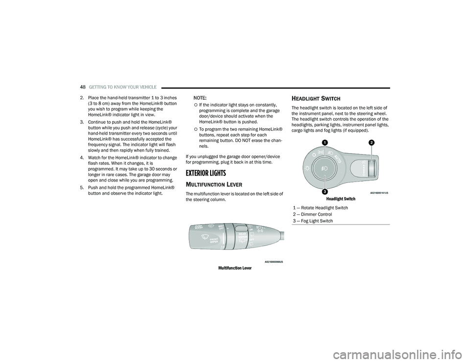
The multifunction lever is located on the left side of
the steering column.
Multifunction Lever
HEADLIGHT SWITCH
The headlight switch is located on the left side of
the instrument panel, next to the steering wheel.
The headlight switch controls the operation of the
headlights, parking lights, instrument panel lights,
cargo lights and fog lights (if equipped).
Headlight Switch
1 — Rotate Headlight Switch
2 — Dimmer Control
3 — Fog Light Switch
21_WD_OM_EN_USC_t.book Page 48
Page 53 of 340
GETTING TO KNOW YOUR VEHICLE51
HEADLIGHT DELAY
To assist when exiting the vehicle, the headlight
delay feature will leave the headlights on for up to
90 seconds. This delay is initiated when the
ignition is placed in the OFF position while the
headlight switch is on, and then the headlight
switch is cycled off. Headlight delay can be
canceled by either turning the headlight switch on
then off, or by placing the ignition in the ON
position.
NOTE:The headlight delay time is programmable through
the Uconnect system Úpage 159.
LIGHTS-ON REMINDER
If the headlights, parking lights, or cargo lights are
left on after the ignition is placed in the OFF
position, the vehicle will chime when the driver’s
door is opened.
FOG LIGHTS — IF EQUIPPED
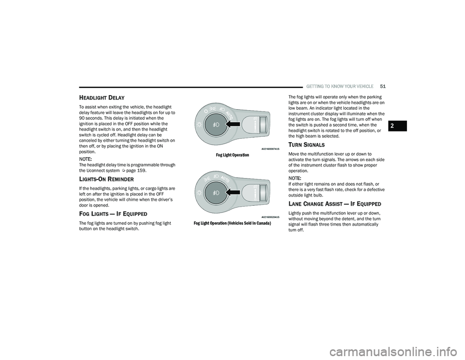
The fog lights are turned on by pushing fog light
button on the headlight switch.
Fog Light Operation
Fog Light Operation (Vehicles Sold In Canada)
The fog lights will operate only when the parking
lights are on or when the vehicle headlights are on
low beam. An indicator light located in the
instrument cluster display will illuminate when the
fog lights are on. The fog lights will turn off when
the switch is pushed a second time, when the
headlight switch is rotated to the off position, or
the high beam is selected.
TURN SIGNALS
Move the multifunction lever up or down to
activate the turn signals. The arrows on each side
of the instrument cluster flash to show proper
operation.
NOTE:If either light remains on and does not flash, or
there is a very fast flash rate, check for a defective
outside light bulb.
LANE CHANGE ASSIST — IF EQUIPPED
Lightly push the multifunction lever up or down,
without moving beyond the detent, and the turn
signal will flash three times then automatically
turn off.
2
21_WD_OM_EN_USC_t.book Page 51
Page 54 of 340
52GETTING TO KNOW YOUR VEHICLE
AUTOMATIC HEADLIGHT LEVELING —
I
F EQUIPPED
This feature prevents the headlights from
interfering with the vision of oncoming drivers.
Headlight leveling automatically adjusts the height
of the headlight beam in reaction to changes in
vehicle pitch.
BATTERY SAVER
Timers are set to both the interior and exterior
lights to protect the life of your vehicle’s battery.
After 10 minutes, if the ignition is OFF and any door
is left open or the dimmer control is rotated all the
way up to the dome light on position, the interior
lights will automatically turn off.
NOTE:Battery saver mode is canceled if the ignition is ON.
If the headlights remain on while the ignition is
placed in the OFF position, the exterior lights will
automatically turn off after eight minutes. If the
headlights are turned on and left on for eight
minutes while the ignition is OFF, the exterior lights
will automatically turn off.
INTERIOR LIGHTS
COURTESY LIGHTS
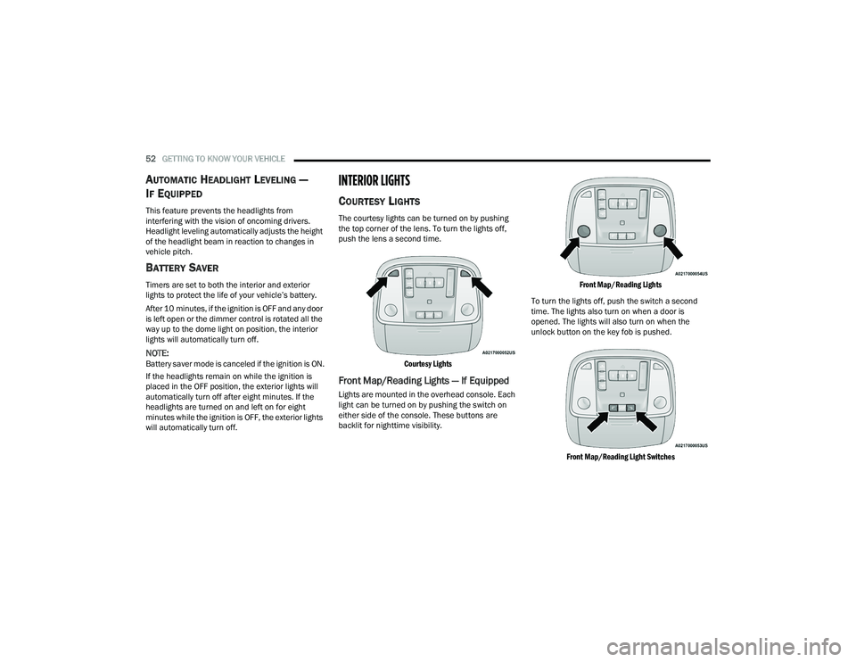
The courtesy lights can be turned on by pushing
the top corner of the lens. To turn the lights off,
push the lens a second time.
Courtesy Lights
Front Map/Reading Lights — If Equipped
Lights are mounted in the overhead console. Each
light can be turned on by pushing the switch on
either side of the console. These buttons are
backlit for nighttime visibility.
Front Map/Reading Lights
To turn the lights off, push the switch a second
time. The lights also turn on when a door is
opened. The lights will also turn on when the
unlock button on the key fob is pushed.
Front Map/Reading Light Switches
21_WD_OM_EN_USC_t.book Page 52
Page 71 of 340
GETTING TO KNOW YOUR VEHICLE69
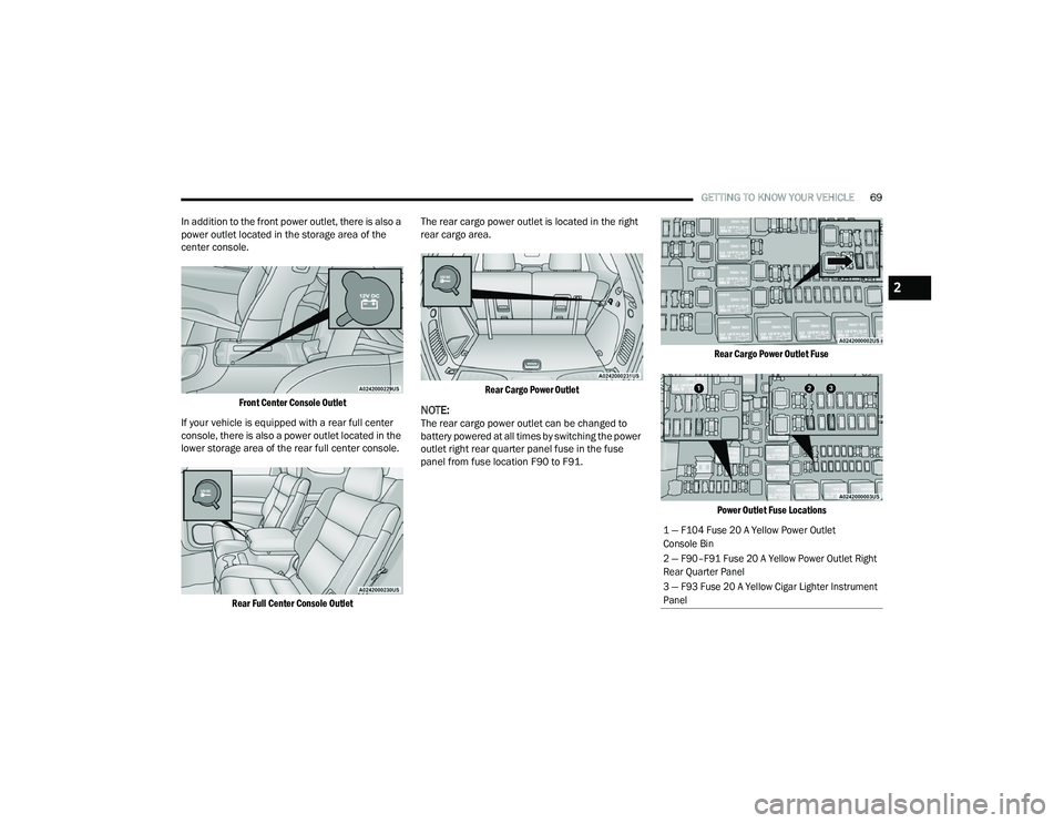
In addition to the front power outlet, there is also a
power outlet located in the storage area of the
center console.
Front Center Console Outlet
If your vehicle is equipped with a rear full center
console, there is also a power outlet located in the
lower storage area of the rear full center console.
Rear Full Center Console Outlet
The rear cargo power outlet is located in the right
rear cargo area.
Rear Cargo Power Outlet
NOTE:The rear cargo power outlet can be changed to
battery powered at all times by switching the power
outlet right rear quarter panel fuse in the fuse
panel from fuse location F90 to F91.
Rear Cargo Power Outlet Fuse
Power Outlet Fuse Locations
1 — F104 Fuse 20 A Yellow Power Outlet
Console Bin
2 — F90–F91 Fuse 20 A Yellow Power Outlet Right
Rear Quarter Panel
3 — F93 Fuse 20 A Yellow Cigar Lighter Instrument
Panel
2
21_WD_OM_EN_USC_t.book Page 69
Page 87 of 340
GETTING TO KNOW YOUR INSTRUMENT PANEL85
The instrument cluster display is located in the
center portion of the cluster and consist of multiple
sections:
Main Screen — The inner ring of the display will
illuminate in gray under normal conditions,
yellow for non critical warnings, red for critical
warnings, and white for on demand information.
Submenu Dots — Whenever there are
submenus available, the position within the
submenus is shown here.
Reconfigurable Telltales/Information
Gear Selector Status (PRND)
Driver Interactive Display (Compass, Temp,
Range to Empty, Trip A, Trip B, Average Fuel
Economy, Current Fuel Economy, Time, Trailer
Trip and Gain)
All Wheel Drive (AWD) Status — If Equipped
The instrument cluster display will normally display
the main menu or the screens of a selected feature
of the main menu. The main display area also
displays “pop-up” messages that consist of
approximately 60 possible warning or information
messages. These pop-up messages fall into
several categories:
Five Second Stored Messages
When the appropriate conditions occur, this
type of message takes control of the main
display area for five seconds and then returns to
the previous screen. Most of the messages of
this type are then stored (as long as the condi-
tion that activated it remains active) and can be
reviewed from the “Messages” main menu item.
Examples of this message type are “Right Front
Turn Signal Lamp Out” and “Low Tire Pressure.”
Unstored Messages
This message type is displayed indefinitely or
until the condition that activated the message is
cleared. Examples of this message type are
“Turn Signal On” (if a turn signal is left on) and
“Lights On” (if driver leaves the vehicle with the
lights on).
Unstored Messages Until RUN
These messages deal primarily with the Remote
Start feature. This message type is displayed
until the ignition is in the RUN state. Examples of
this message type are “Remote Start Canceled -
Door Ajar” and “Press Brake Pedal and Push
Button to Start.”
Five Second Unstored Messages
When the appropriate conditions occur, this
type of message takes control of the main
display area for five seconds and then returns to
the previous screen. An example of this
message type is “Automatic High Beams On.”
ENGINE OIL LIFE RESET
Oil Change Required
Your vehicle is equipped with an engine oil change
indicator system. The “Oil Change Required”
message will display in the instrument cluster
display for five seconds after a single chime has
sounded, to indicate the next scheduled oil change
interval. The engine oil change indicator system is
duty cycle based, which means the engine oil
change interval may fluctuate, dependent upon
your personal driving style.
Unless reset, this message will continue to display
each time the ignition is placed in the ON/RUN
position. To turn off the message temporarily, push
and release the OK or arrow buttons. To reset the
oil change indicator system (after performing the
scheduled maintenance), refer to the following
procedure.3
21_WD_OM_EN_USC_t.book Page 85
Page 88 of 340
86GETTING TO KNOW YOUR INSTRUMENT PANEL
Vehicles Equipped With Keyless Enter ‘n Go —
Ignition
Use the steering wheel instrument cluster display
controls for the following procedure(s):
1. Without pressing the brake pedal, push the ENGINE START/STOP button and place the
ignition in the ON/RUN position (do not start
the engine).
2. Push and release the down arrow button to
scroll downward through the main menu to
“Vehicle Info.”
3. Push and release the right arrow button to access the ”Oil Life” screen.
4. Push and hold the OK button to reset oil life. If
conditions are met, the gauge and numeric
display will update to show 100%. If conditions
are not met a pop-up message of “To reset oil
life engine must be off with ignition in run” will
be displayed (for five seconds), and the user
will remain at the Oil Life screen.
5. Push and release the up or down arrow
button to exit the submenu screen.
NOTE:If the indicator message illuminates when you start
the vehicle, the oil change indicator system did not
reset. If necessary, repeat this procedure. Secondary Method Of Resetting Engine Oil Life
1. Without pressing the brake pedal, push the
ENGINE START/STOP button and place the
ignition to the ON/RUN position (do not start
the engine).
2. Fully press the accelerator pedal, slowly, three times within 10 seconds.
3. Without pushing the brake pedal, push the ENGINE START/STOP button once to return the
ignition to the OFF position.
NOTE:If the indicator message illuminates when you start
the vehicle, the oil change indicator system did not
reset. If necessary, repeat this procedure.
DISPLAY AND MESSAGES
Includes the following, but not limited to:
Front Seat Belts Unbuckled
Driver Seat Belt Unbuckled
Passenger Seat Belt Unbuckled
Traction Control Off
Washer Fluid Low
Oil Pressure Low
Oil Change Due
Fuel Low
Service Anti-lock Brake System
Service Electronic Throttle Control
Service Power Steering
Cruise Off
Cruise Ready
ACC Override
Cruise Set To XXX mph or km/h
Tire Pressure Screen With Low Tire(s)
Service Tire Pressure System
Park Brake Engaged
Brake Fluid Low
Engine Temperature Hot
Lights On
Right Front Turn Signal Light Out
Right Rear Turn Signal Light Out
Left Front Turn Signal Light Out
Left Rear Turn Signal Light Out
Ignition or Accessory On
Vehicle Not In Park
Remote Start Active Push Start Button
Remote Start Canceled Fuel Low
Remote Start Canceled Door Open
Remote Start Canceled Hood Open
21_WD_OM_EN_USC_t.book Page 86