check engine DODGE DURANGO 2021 Owners Manual
[x] Cancel search | Manufacturer: DODGE, Model Year: 2021, Model line: DURANGO, Model: DODGE DURANGO 2021Pages: 340, PDF Size: 20.38 MB
Page 8 of 340
6
IN CASE OF EMERGENCY
HAZARD WARNING FLASHERS ........................ 243
ASSIST AND SOS MIRROR — IF EQUIPPED...... 243
JACKING AND TIRE CHANGING ........................ 247 Preparations For Jacking ............................ 247
Jack Location ................................................. 248
Spare Tire Stowage ....................................... 249
Spare Tire Removal ....................................... 249
Jacking Instructions ..................................... 251
JUMP STARTING .................................................. 255
Preparations For Jump Start......................... 255Jump Starting Procedure .............................. 256
REFUELING IN EMERGENCY –
IF EQUIPPED ........................................................ 257
IF YOUR ENGINE OVERHEATS ............................ 258
MANUAL PARK RELEASE ................................... 258
FREEING A STUCK VEHICLE .............................. 260
TOWING A DISABLED VEHICLE .........................261
Rear Wheel Drive Models ............................. 262
All Wheel Drive Models ................................. 263
ENHANCED ACCIDENT RESPONSE SYSTEM
(EARS) .................................................................. 263
EVENT DATA RECORDER (EDR) ......................... 263
SERVICING AND MAINTENANCE
SCHEDULED SERVICING ................................... 264
Maintenance Plan ......................................... 265
ENGINE COMPARTMENT .................................... 268
3.6L Engine ................................................... 268
5.7L Engine ................................................... 269
Checking Oil Level ......................................... 270
Adding Washer Fluid .................................... 270
Maintenance-Free Battery ........................... 270Pressure Washing ......................................... 271
VEHICLE MAINTENANCE..................................... 271
Engine Oil ...................................................... 271
Engine Oil Filter ............................................ 272
Engine Air Cleaner Filter ............................ 272
Air Conditioner Maintenance ..................... 273
Accessory Drive Belt Inspection ................... 275Body Lubrication .......................................... 276
Windshield Wiper Blades ............................. 276
Exhaust System ............................................ 279
Cooling System .............................................. 280
Brake System ............................................... 283
Automatic Transmission ............................... 284
Front/Rear Axle Fluid ................................... 285Transfer Case ............................................... 285
Fuses.............................................................. 286
Bulb Replacement......................................... 293 TIRES ..................................................................... 295
Tire Safety Information ................................. 295
Tires — General Information ........................ 303Tire Types....................................................... 306Spare Tires — If Equipped ............................ 307
Wheel And Wheel Trim Care ........................ 309Snow Traction Devices ................................. 310
Tire Rotation Recommendations ................ 312
DEPARTMENT OF TRANSPORTATION
UNIFORM TIRE QUALITY GRADES .................... 312
Treadwear...................................................... 312
Traction Grades ............................................. 313Temperature Grades..................................... 313
STORING THE VEHICLE .................................... 313
BODYWORK .......................................................... 313 Protection From Atmospheric Agents .......... 313
Body And Underbody Maintenance ............. 314
Preserving The Bodywork ............................. 314
INTERIORS ........................................................... 315
Seats And Fabric Parts ................................. 315
Plastic And Coated Parts .............................. 315
Leather Surfaces........................................... 316
Glass Surfaces ............................................. 316
21_WD_OM_EN_USC_t.book Page 6
Page 13 of 340
11
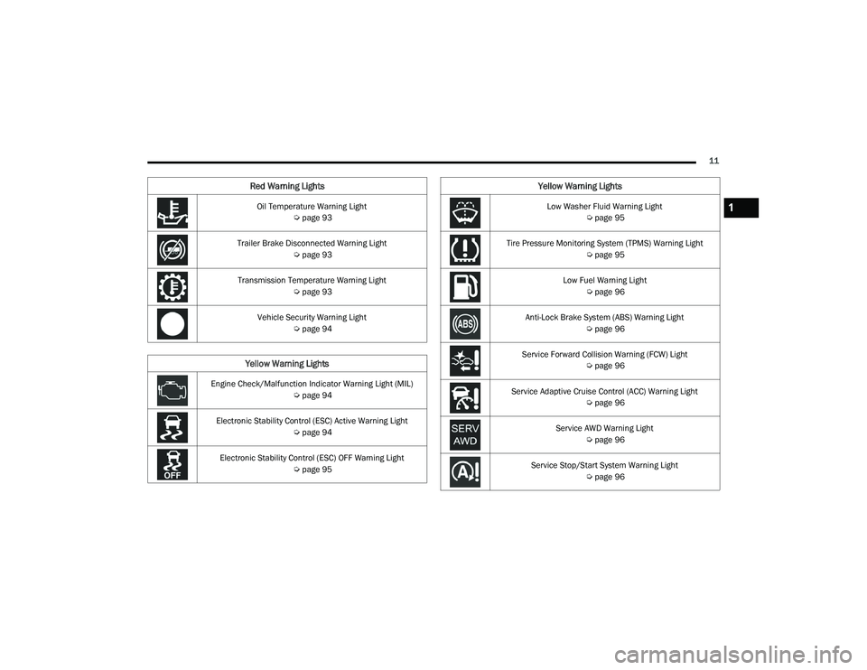
Oil Temperature Warning Light Úpage 93
Trailer Brake Disconnected Warning Light Úpage 93
Transmission Temperature Warning Light Úpage 93
Vehicle Security Warning Light Úpage 94
Yellow Warning Lights
Engine Check/Malfunction Indicator Warning Light (MIL)
Úpage 94
Electronic Stability Control (ESC) Active Warning Light Úpage 94
Electronic Stability Control (ESC) OFF Warning Light Úpage 95
Red Warning Lights
Low Washer Fluid Warning Light
Úpage 95
Tire Pressure Monitoring System (TPMS) Warning Light Úpage 95
Low Fuel Warning Light Úpage 96
Anti-Lock Brake System (ABS) Warning Light Úpage 96
Service Forward Collision Warning (FCW) Light Úpage 96
Service Adaptive Cruise Control (ACC) Warning Light Úpage 96
Service AWD Warning Light Úpage 96
Service Stop/Start System Warning Light Úpage 96
Yellow Warning Lights
1
21_WD_OM_EN_USC_t.book Page 11
Page 19 of 340
GETTING TO KNOW YOUR VEHICLE17
The system uses a key fob, keyless push button
ignition and a Radio Frequency (RF) receiver to
prevent unauthorized vehicle operation. Therefore,
only key fobs that are programmed to the vehicle
can be used to start and operate the vehicle. The
system will shut the engine off in two seconds if an
incorrect key fob is used to start the engine.
After placing the ignition in the ON/RUN position,
the Vehicle Security Light will turn on for three
seconds for a bulb check. If the light remains on
after the bulb check, it indicates that there is a
problem with the electronics. In addition, if the light
begins to flash after the bulb check, it indicates
that someone used an invalid key fob to start the
engine. Either of these conditions will result in the
engine being shut off after two seconds.
If the Vehicle Security Light turns on during normal
vehicle operation (vehicle running for longer than
10 seconds), it indicates that there is a fault in the
electronics. Should this occur, have the vehicle
serviced as soon as possible by an authorized
dealer. All of the key fobs provided with your new vehicle
have been programmed to the vehicle electronics
Ú
page 327.
IGNITION SWITCH
KEYLESS ENTER ‘N GO™ IGNITION
This feature allows the driver to operate the
ignition switch with the push of a button as long as
the key fob is in the passenger compartment.
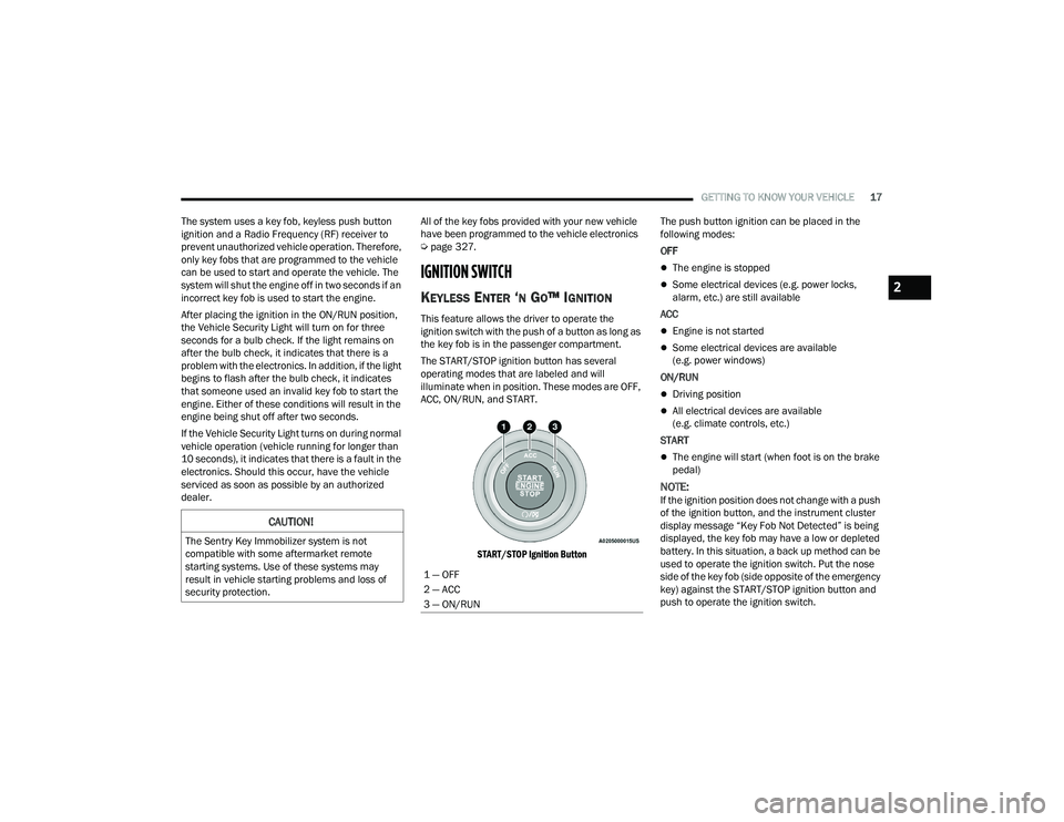
The START/STOP ignition button has several
operating modes that are labeled and will
illuminate when in position. These modes are OFF,
ACC, ON/RUN, and START.
START/STOP Ignition Button
The push button ignition can be placed in the
following modes:
OFF
The engine is stopped
Some electrical devices (e.g. power locks,
alarm, etc.) are still available
ACC
Engine is not started
Some electrical devices are available
(e.g. power windows)
ON/RUN
Driving position
All electrical devices are available
(e.g. climate controls, etc.)
START
The engine will start (when foot is on the brake
pedal)
NOTE:If the ignition position does not change with a push
of the ignition button, and the instrument cluster
display message “Key Fob Not Detected” is being
displayed, the key fob may have a low or depleted
battery. In this situation, a back up method can be
used to operate the ignition switch. Put the nose
side of the key fob (side opposite of the emergency
key) against the START/STOP ignition button and
push to operate the ignition switch.
CAUTION!
The Sentry Key Immobilizer system is not
compatible with some aftermarket remote
starting systems. Use of these systems may
result in vehicle starting problems and loss of
security protection.
1 — OFF
2 — ACC
3 — ON/RUN
2
21_WD_OM_EN_USC_t.book Page 17
Page 72 of 340
70GETTING TO KNOW YOUR VEHICLE
(Continued)
POWER INVERTER — IF EQUIPPED
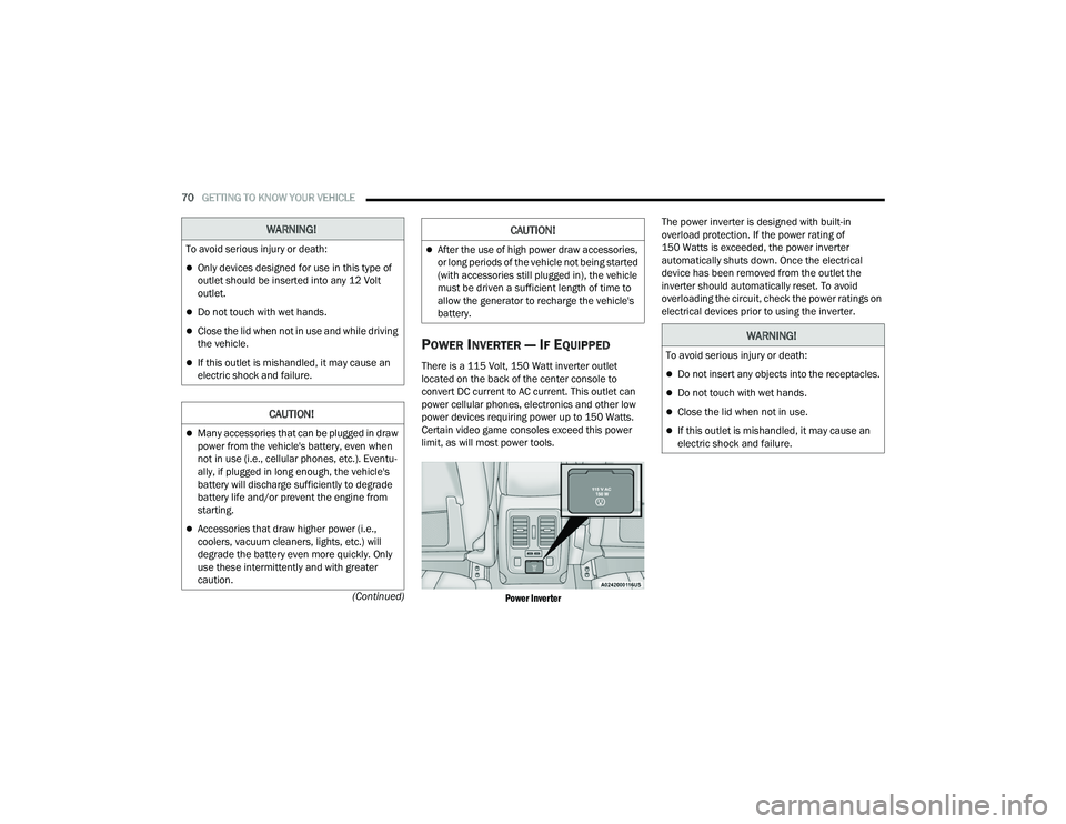
There is a 115 Volt, 150 Watt inverter outlet
located on the back of the center console to
convert DC current to AC current. This outlet can
power cellular phones, electronics and other low
power devices requiring power up to 150 Watts.
Certain video game consoles exceed this power
limit, as will most power tools.
Power Inverter
The power inverter is designed with built-in
overload protection. If the power rating of
150 Watts is exceeded, the power inverter
automatically shuts down. Once the electrical
device has been removed from the outlet the
inverter should automatically reset. To avoid
overloading the circuit, check the power ratings on
electrical devices prior to using the inverter.
WARNING!
To avoid serious injury or death:
Only devices designed for use in this type of
outlet should be inserted into any 12 Volt
outlet.
Do not touch with wet hands.
Close the lid when not in use and while driving
the vehicle.
If this outlet is mishandled, it may cause an
electric shock and failure.
CAUTION!
Many accessories that can be plugged in draw
power from the vehicle's battery, even when
not in use (i.e., cellular phones, etc.). Eventu
-
ally, if plugged in long enough, the vehicle's
battery will discharge sufficiently to degrade
battery life and/or prevent the engine from
starting.
Accessories that draw higher power (i.e.,
coolers, vacuum cleaners, lights, etc.) will
degrade the battery even more quickly. Only
use these intermittently and with greater
caution.
After the use of high power draw accessories,
or long periods of the vehicle not being started
(with accessories still plugged in), the vehicle
must be driven a sufficient length of time to
allow the generator to recharge the vehicle's
battery.
CAUTION!
WARNING!
To avoid serious injury or death:
Do not insert any objects into the receptacles.
Do not touch with wet hands.
Close the lid when not in use.
If this outlet is mishandled, it may cause an
electric shock and failure.
21_WD_OM_EN_USC_t.book Page 70
Page 85 of 340
GETTING TO KNOW YOUR INSTRUMENT PANEL83
INSTRUMENT CLUSTER DESCRIPTIONS
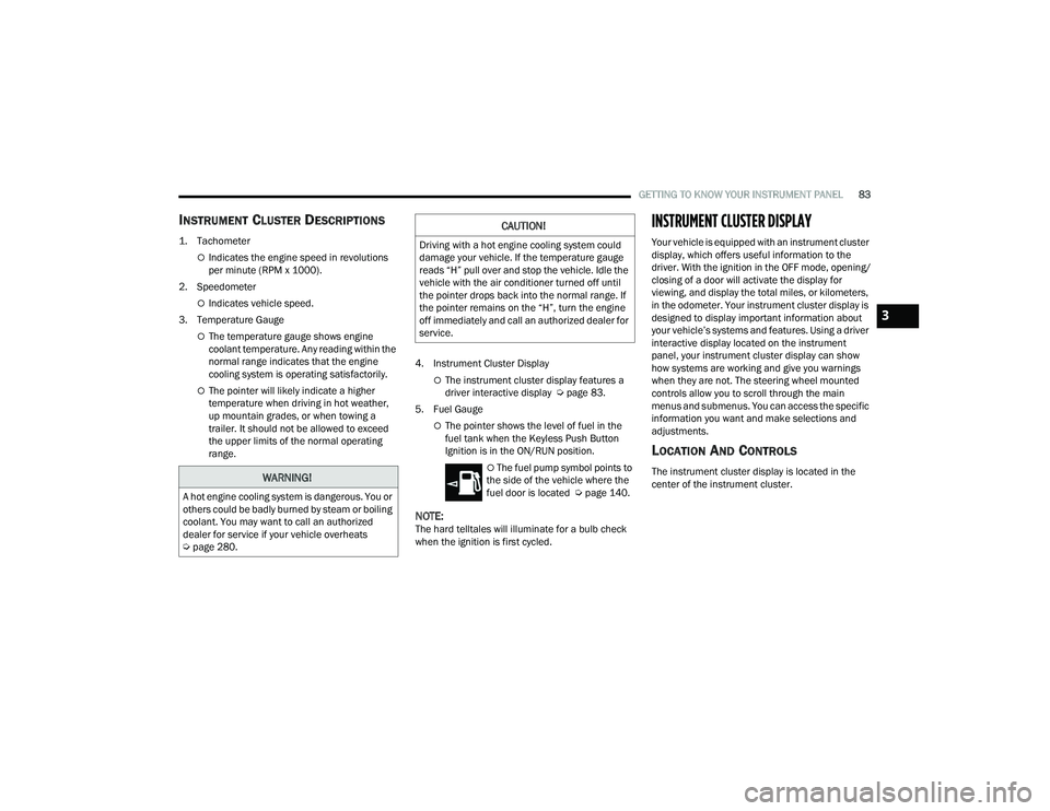
1. Tachometer
Indicates the engine speed in revolutions
per minute (RPM x 1000).
2. Speedometer
Indicates vehicle speed.
3. Temperature Gauge
The temperature gauge shows engine
coolant temperature. Any reading within the
normal range indicates that the engine
cooling system is operating satisfactorily.
The pointer will likely indicate a higher
temperature when driving in hot weather,
up mountain grades, or when towing a
trailer. It should not be allowed to exceed
the upper limits of the normal operating
range. 4. Instrument Cluster DisplayThe instrument cluster display features a
driver interactive display Ú
page 83.
5. Fuel Gauge
The pointer shows the level of fuel in the
fuel tank when the Keyless Push Button
Ignition is in the ON/RUN position.
The fuel pump symbol points to
the side of the vehicle where the
fuel door is located Ú page 140.
NOTE:The hard telltales will illuminate for a bulb check
when the ignition is first cycled.
INSTRUMENT CLUSTER DISPLAY
Your vehicle is equipped with an instrument cluster
display, which offers useful information to the
driver. With the ignition in the OFF mode, opening/
closing of a door will activate the display for
viewing, and display the total miles, or kilometers,
in the odometer. Your instrument cluster display is
designed to display important information about
your vehicle’s systems and features. Using a driver
interactive display located on the instrument
panel, your instrument cluster display can show
how systems are working and give you warnings
when they are not. The steering wheel mounted
controls allow you to scroll through the main
menus and submenus. You can access the specific
information you want and make selections and
adjustments.
LOCATION AND CONTROLS
The instrument cluster display is located in the
center of the instrument cluster.WARNING!
A hot engine cooling system is dangerous. You or
others could be badly burned by steam or boiling
coolant. You may want to call an authorized
dealer for service if your vehicle overheats
Úpage 280.
CAUTION!
Driving with a hot engine cooling system could
damage your vehicle. If the temperature gauge
reads “H” pull over and stop the vehicle. Idle the
vehicle with the air conditioner turned off until
the pointer drops back into the normal range. If
the pointer remains on the “H”, turn the engine
off immediately and call an authorized dealer for
service.
3
21_WD_OM_EN_USC_t.book Page 83
Page 92 of 340
90GETTING TO KNOW YOUR INSTRUMENT PANEL
When load reduction is activated, the message
“Battery Saver On” or “Battery Saver Mode” will
appear in the instrument cluster.
These messages indicate the vehicle battery has a
low state of charge and continues to lose electrical
charge at a rate that the charging system cannot
sustain.
NOTE:
The charging system is independent from load
reduction. The charging system performs a diag -
nostic on the charging system continuously.
If the Battery Charge Warning Light is on it may
indicate a problem with the charging system
Ú page 92.
The electrical loads that may be switched off
(if equipped), and vehicle functions which can be
affected by load reduction:
Heated Seat/Vented Seats/Heated Wheel
Rear Defroster And Heated Mirrors
HVAC System
115 Volt AC Power Inverter System
Audio and Telematics System Loss of the battery charge may indicate one or
more of the following conditions:
The charging system cannot deliver enough
electrical power to the vehicle system because
the electrical loads are larger than the capability
of the charging system. The charging system is
still functioning properly.
Turning on all possible vehicle electrical loads
(e.g. HVAC to max settings, exterior and interior
lights, overloaded power outlets +12 Volt,
115 Volt AC, USB ports) during certain driving
conditions (city driving, towing, frequent stop
-
ping, etc.).
Installing options like additional lights, upfitter
electrical accessories, audio systems, alarms
and similar devices.
Unusual driving cycles (short trips separated by
long parking periods).
The vehicle was parked for an extended period
of time (weeks, months).
The battery was recently replaced and was not
charged completely.
The battery was discharged by an electrical load
left on when the vehicle was parked.
The battery was used for an extended period
with the engine not running to supply radio,
lights, chargers, +12 Volt portable appliances
like vacuum cleaners, game consoles and
similar devices. What to do when an electrical load reduction
action message is present (“Battery Saver On” or
“Battery Saver Mode”)
During a trip:
Reduce power to unnecessary loads if possible:
Turn off redundant lights (interior or
exterior)
Check what may be plugged in to power
outlets +12 Volt, 115 Volt AC, USB ports
Check HVAC settings (blower, temperature)
Check the audio settings (volume)
After a trip:
Check if any aftermarket equipment was
installed (additional lights, upfitter electrical
accessories, audio systems, alarms) and review
specifications if any (load and Ignition Off Draw
currents).
Evaluate the latest driving cycles (distance,
driving time and parking time).
The vehicle should have service performed if
the message is still present during consecutive
trips, and if the evaluation and driving pattern of
the vehicle did not help to identify the cause.
21_WD_OM_EN_USC_t.book Page 90
Page 94 of 340
92GETTING TO KNOW YOUR INSTRUMENT PANEL
Vehicles equipped with the Anti-Lock Brake System
(ABS) are also equipped with Electronic Brake
Force Distribution (EBD). In the event of an EBD
failure, the Brake Warning Light will turn on along
with the ABS Light. Immediate repair to the ABS
system is required.
Operation of the Brake Warning Light can be
checked by turning the ignition switch from the OFF
position to the ON/RUN position. The light should
illuminate for approximately two seconds. The light
should then turn off unless the parking brake is
applied or a brake fault is detected. If the light does
not illuminate, have the light inspected by an
authorized dealer.
The light also will turn on when the parking brake
is applied with the ignition switch in the ON/RUN
position.
NOTE:This light shows only that the parking brake is
applied. It does not show the degree of brake appli -
cation.
Battery Charge Warning Light
This warning light will illuminate when the
battery is not charging properly. If it stays
on while the engine is running, there may
be a malfunction with the charging
system. Contact an authorized dealer as soon as
possible. This indicates a possible problem with the
electrical system or a related component.
Door Open Warning Light — If Equipped
This indicator will illuminate when a door
is ajar/open and not fully closed.
NOTE:If the vehicle is moving, there will also be a single
chime.
Electric Power Steering (EPS) Fault
Warning Light
This warning light will turn on when
there's a fault with the EPS system
Ú
page 117.
Electronic Throttle Control (ETC) Warning
Light
This warning light will illuminate to
indicate a problem with the ETC system.
If a problem is detected while the vehicle
is running, the light will either stay on or
flash depending on the nature of the problem.
Cycle the ignition when the vehicle is safely and
completely stopped and the transmission is placed
in the PARK (P) position. The light should turn off.
If the light remains on with the vehicle running,
your vehicle will usually be drivable; however, see
an authorized dealer for service as soon as
possible.
NOTE:This light may turn on if the accelerator and brake
pedals are pressed at the same time.
If the light continues to flash when the vehicle is
running, immediate service is required and you
may experience reduced performance, an
elevated/rough idle, or engine stall and your
vehicle may require towing. The light will come
on when the ignition is placed in the ON/RUN or
ACC/ON/RUN position and remain on briefly as a
bulb check. If the light does not come on during
starting, have the system checked by an
authorized dealer.
WARNING!
Continued operation with reduced assist could
pose a safety risk to yourself and others. Service
should be obtained as soon as possible.
21_WD_OM_EN_USC_t.book Page 92
Page 95 of 340
GETTING TO KNOW YOUR INSTRUMENT PANEL93
Engine Coolant Temperature Warning
Light
This warning light warns of an
overheated engine condition. If the
engine coolant temperature is too high,
this indicator will illuminate and a single
chime will sound. If the temperature reaches the
upper limit, a continuous chime will sound for four
minutes or until the engine is able to cool,
whichever comes first.
If the light turns on while driving, safely pull over
and stop the vehicle. If the Air Conditioning (A/C)
system is on, turn it off. Also, shift the transmission
into NEUTRAL (N) and idle the vehicle. If the
temperature reading does not return to normal,
turn the engine off immediately and call for service
Ú page 258.
Hood Open Warning Light
This warning light will illuminate when the
hood is left open and not fully closed.
NOTE:If the vehicle is moving, there will also be a single
chime.
Liftgate Open Warning Light
This warning light will illuminate when the
liftgate is open.
NOTE:If the vehicle is moving, there will also be a single
chime.
Oil Pressure Warning Light
This warning light will illuminate to
indicate low engine oil pressure. If the
light turns on while driving, stop the
vehicle, shut off the engine as soon as
possible, and contact an authorized dealer. A
chime will sound when this light turns on.
Do not operate the vehicle until the cause is
corrected. This light does not indicate how much oil
is in the engine. The engine oil level must be
checked under the hood.
Oil Temperature Warning Light
This warning light will illuminate to
indicate the engine oil temperature is
high. If the light turns on while driving,
stop the vehicle and shut off the engine
as soon as possible. Wait for oil temperature to
return to normal levels.
Trailer Brake Disconnected Warning Light
This warning light will illuminate when the
Trailer Brake has been disconnected
Ú page 147.
Transmission Temperature Warning
Light — If Equipped
This warning light will illuminate to warn
of a high transmission fluid temperature.
This may occur with strenuous usage
such as trailer towing. If this light turns
on, stop the vehicle and run the engine at idle or
slightly faster, with the transmission in PARK (P) or
NEUTRAL (N), until the light turns off. Once the light
turns off, you may continue to drive normally.
WARNING!
If you continue operating the vehicle when the
Transmission Temperature Warning Light is
illuminated you could cause the fluid to boil over,
come in contact with hot engine or exhaust
components and cause a fire.
CAUTION!
Continuous driving with the Transmission
Temperature Warning Light illuminated will
eventually cause severe transmission damage
or transmission failure.
3
21_WD_OM_EN_USC_t.book Page 93
Page 96 of 340
94GETTING TO KNOW YOUR INSTRUMENT PANEL
Vehicle Security Warning Light —
If Equipped
This light will flash at a fast rate for
approximately 15 seconds when the
vehicle security system is arming, and
then will flash slowly until the vehicle is
disarmed.
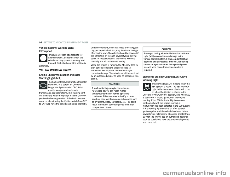
YELLOW WARNING LIGHTS
Engine Check/Malfunction Indicator
Warning Light (MIL)
The Engine Check/Malfunction Indicator
Light (MIL) is a part of an Onboard
Diagnostic System called OBD II that
monitors engine and automatic
transmission control systems. This warning light
will illuminate when the ignition is in the ON/RUN
position before engine start. If the bulb does not
come on when turning the ignition switch from OFF
to ON/RUN, have the condition checked promptly. Certain conditions, such as a loose or missing gas
cap, poor quality fuel, etc., may illuminate the light
after engine start. The vehicle should be serviced if
the light stays on through several typical driving
styles. In most situations, the vehicle will drive
normally and will not require towing.
When the engine is running, the MIL may flash to
alert serious conditions that could lead to
immediate loss of power or severe catalytic
converter damage. The vehicle should be serviced
by an authorized dealer as soon as possible if this
occurs.
Electronic Stability Control (ESC) Active
Warning Light
This warning light will indicate when the
ESC system is Active. The ESC Indicator
Light in the instrument cluster will come
on when the ignition is placed in the
ON/RUN or ACC/ON/RUN position, and when ESC
is activated. It should go out with the engine
running. If the ESC Indicator Light comes on
continuously with the engine running, a
malfunction has been detected in the ESC system.
If this warning light remains on after several
ignition cycles, and the vehicle has been driven
several miles (kilometers) at speeds greater than
30 mph (48 km/h), see an authorized dealer as
soon as possible to have the problem diagnosed
and corrected.WARNING!
A malfunctioning catalytic converter, as
referenced above, can reach higher
temperatures than in normal operating
conditions. This can cause a fire if you drive
slowly or park over flammable substances such
as dry plants, wood, cardboard, etc. This could
result in death or serious injury to the driver,
occupants or others.
CAUTION!
Prolonged driving with the Malfunction Indicator
Light (MIL) on could cause damage to the
vehicle control system. It also could affect fuel
economy and driveability. If the MIL is flashing,
severe catalytic converter damage and power
loss will soon occur. Immediate service is
required.
21_WD_OM_EN_USC_t.book Page 94
Page 102 of 340
100GETTING TO KNOW YOUR INSTRUMENT PANEL
EMISSIONS INSPECTION AND
MAINTENANCE PROGRAMS
In some localities, it may be a legal requirement to
pass an inspection of your vehicle's emissions
control system. Failure to pass could prevent
vehicle registration.
For states that require an Inspection and
Maintenance (I/M), this check verifies
the Malfunction Indicator Light (MIL) is
functioning and is not on when the
engine is running, and that the OBD II system is
ready for testing.
Normally, the OBD II system will be ready. The
OBD II system may not be ready if your vehicle was
recently serviced, recently had a depleted battery
or a battery replacement. If the OBD II system
should be determined not ready for the I/M test,
your vehicle may fail the test. Your vehicle has a simple ignition actuated test,
which you can use prior to going to the test station.
To check if your vehicle's OBD II system is ready,
you must do the following:
1. Cycle the ignition switch to the ON position,
but do not crank or start the engine.
NOTE:If you crank or start the engine, you will have to
start this test over.
2. As soon as you cycle the ignition switch to the ON position, you will see the Malfunction
Indicator Light (MIL) symbol come on as part of
a normal bulb check.
3. Approximately 15 seconds later, one of two things will happen:
The MIL will flash for about 10 seconds and
then return to being fully illuminated until
you turn OFF the ignition or start the engine.
This means that your vehicle's OBD II
system is not ready and you should not
proceed to the I/M station.
The MIL will not flash at all and will remain
fully illuminated until you place the ignition
in the off position or start the engine. This
means that your vehicle's OBD II system is
ready and you can proceed to the I/M
station. If your OBD II system is
not ready, you should see
an authorized dealer or repair facility. If your
vehicle was recently serviced or had a battery
failure or replacement, you may need to do nothing
more than drive your vehicle as you normally would
in order for your OBD II system to update. A
recheck with the above test routine may then
indicate that the system is now ready.
Regardless of whether your vehicle's OBD II system
is ready or not, if the MIL is illuminated during
normal vehicle operation you should have your
vehicle serviced before going to the I/M station.
The I/M station can fail your vehicle because the
MIL is on with the engine running.
21_WD_OM_EN_USC_t.book Page 100