ECO mode DODGE DURANGO 2022 User Guide
[x] Cancel search | Manufacturer: DODGE, Model Year: 2022, Model line: DURANGO, Model: DODGE DURANGO 2022Pages: 332, PDF Size: 19.82 MB
Page 51 of 332
GETTING TO KNOW YOUR VEHICLE49
To opt out of the Advanced Auto High-Beam
Sensitivity Control (default) and enter Reduced
High-Beam Sensitivity Control (not recom -
mended), toggle high beam lever six full on/off
cycles within 10 seconds of ignition ON. System
will return to default setting upon ignition off.
FLASH-TO-PASS
You can signal another vehicle with your headlights
by lightly pulling the multifunction lever toward you.
This will cause the high beam headlights to turn on,
and remain on, until the lever is released.
AUTOMATIC HEADLIGHTS
This system automatically turns the headlights on
or off according to ambient light levels. To turn the
system on, rotate the headlight switch
counterclockwise to the AUTO position. When the
system is on, the headlight time delay feature is
also on. This means the headlights will stay on for
up to 90 seconds after you place the ignition into
the OFF position. The headlight time delay can be
programmed 0/30/60/90 seconds within
Uconnect Settings Ú page 156.
To turn the automatic system off, move the
headlight switch out of the AUTO position.
NOTE:The engine must be running before the headlights
will come on in the automatic mode.
PARKING LIGHTS AND PANEL LIGHTS
To turn on the parking lights and instrument panel
lights, rotate the headlight switch clockwise. To
turn off the parking lights, rotate the headlight
switch back to the O (off) position.
NOTE:Vehicles sold in Canada are equipped with a head -
light switch with an AUTO and ON detent but
without an OFF detent. Headlights will be deacti -
vated when the headlight switch is placed in the
parking lights position. However, the Daytime
Running Lights (DRLs) will be activated along with
the front and rear marker lights. The DRLs may be
deactivated when the parking brake is engaged.
AUTOMATIC HEADLIGHTS WITH WIPERS
If your vehicle is equipped with Automatic
Headlights, it also has this
customer-programmable feature. When your
headlights are in the automatic mode and the
engine is running, they will automatically turn on
when the wiper system is on. This feature is
programmable through the Uconnect system
Ú page 156.
NOTE:When your headlights come on during the daytime,
the vehicle will monitor outside brightness and
decide if the instrument panel needs to be dimmed
or not Ú page 51.
HEADLIGHT DELAY
To assist when exiting the vehicle, the headlight
delay feature will leave the headlights on for up to
90 seconds. This delay is initiated when the
ignition is placed in the OFF position while the
headlight switch is on, and then the headlight
switch is cycled off. Headlight delay can be
canceled by either turning the headlight switch on
then off, or by placing the ignition in the ON
position.
NOTE:The headlight delay time is programmable through
the Uconnect system Ú page 156.
LIGHTS-ON REMINDER
If the headlights, parking lights, or cargo lights are
left on after the ignition is placed in the OFF
position, the vehicle will chime when the driver’s
door is opened.
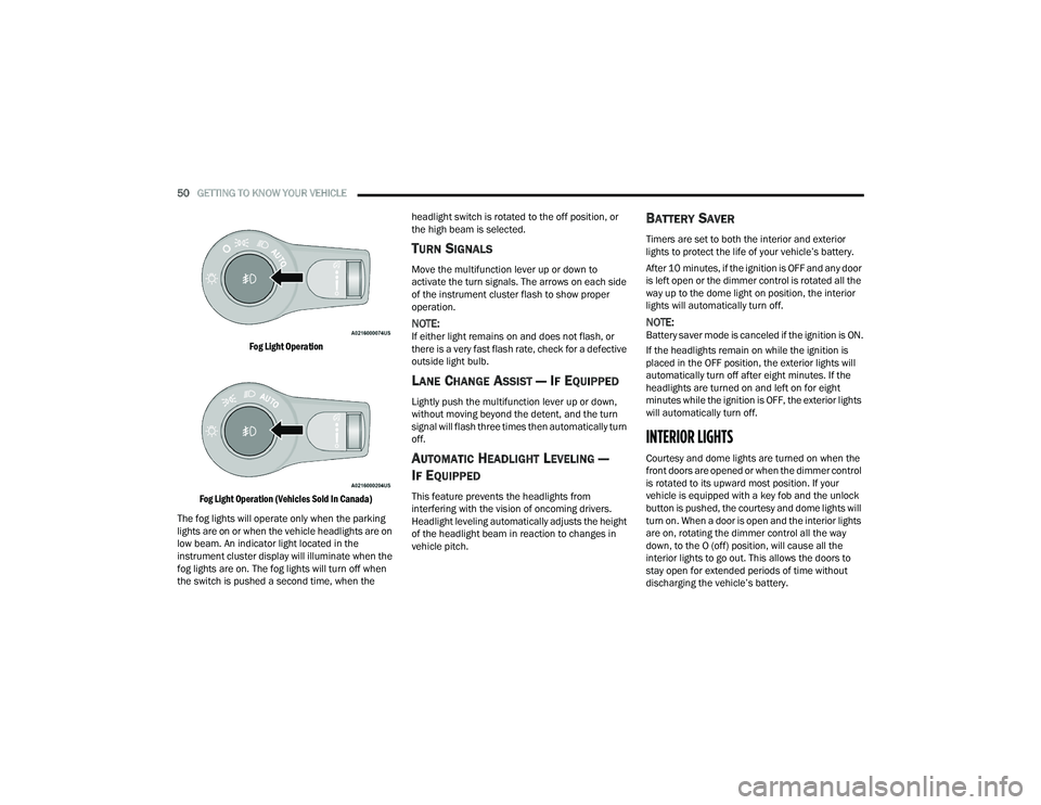
FOG LIGHTS — IF EQUIPPED
The fog lights are turned on by pushing fog light
button on the headlight switch.
2
22_WD_OM_EN_USC_t.book Page 49
Page 52 of 332
50GETTING TO KNOW YOUR VEHICLE
Fog Light Operation
Fog Light Operation (Vehicles Sold In Canada)
The fog lights will operate only when the parking
lights are on or when the vehicle headlights are on
low beam. An indicator light located in the
instrument cluster display will illuminate when the
fog lights are on. The fog lights will turn off when
the switch is pushed a second time, when the headlight switch is rotated to the off position, or
the high beam is selected.
TURN SIGNALS
Move the multifunction lever up or down to
activate the turn signals. The arrows on each side
of the instrument cluster flash to show proper
operation.
NOTE:If either light remains on and does not flash, or
there is a very fast flash rate, check for a defective
outside light bulb.
LANE CHANGE ASSIST — IF EQUIPPED
Lightly push the multifunction lever up or down,
without moving beyond the detent, and the turn
signal will flash three times then automatically turn
off.
AUTOMATIC HEADLIGHT LEVELING —
I
F EQUIPPED
This feature prevents the headlights from
interfering with the vision of oncoming drivers.
Headlight leveling automatically adjusts the height
of the headlight beam in reaction to changes in
vehicle pitch.
BATTERY SAVER
Timers are set to both the interior and exterior
lights to protect the life of your vehicle’s battery.
After 10 minutes, if the ignition is OFF and any door
is left open or the dimmer control is rotated all the
way up to the dome light on position, the interior
lights will automatically turn off.
NOTE:Battery saver mode is canceled if the ignition is ON.
If the headlights remain on while the ignition is
placed in the OFF position, the exterior lights will
automatically turn off after eight minutes. If the
headlights are turned on and left on for eight
minutes while the ignition is OFF, the exterior lights
will automatically turn off.
INTERIOR LIGHTS
Courtesy and dome lights are turned on when the
front doors are opened or when the dimmer control
is rotated to its upward most position. If your
vehicle is equipped with a key fob and the unlock
button is pushed, the courtesy and dome lights will
turn on. When a door is open and the interior lights
are on, rotating the dimmer control all the way
down, to the O (off) position, will cause all the
interior lights to go out. This allows the doors to
stay open for extended periods of time without
discharging the vehicle’s battery.
22_WD_OM_EN_USC_t.book Page 50
Page 56 of 332
54GETTING TO KNOW YOUR VEHICLE
REAR WINDOW WIPER/WASHER
The rear wiper/washer controls are located on the
multifunction lever on the left side of the steering
column. The rear wiper/washer is operated by
rotating a switch, located at the middle of the lever.
Rotate the center portion of the lever
upward to the first detent for intermittent
operation and to the second detent for
continuous rear wiper operation.
Rotate the center portion of the lever
upward to the third detent to activate the
washer. The washer will continue to
operate as long as the switch is held.
Rotate the center portion downward from the
OFF position to activate the rear washer. The
washer will continue to operate as long as the
switch is held.
NOTE:As a protective measure, the pump will stop if the
switch is held for more than 20 seconds. Once the
switch is released the pump will resume normal
operation.
If the rear wiper is operating when the ignition is
placed in the OFF position, the wiper will
automatically return to the “park” position.
CLIMATE CONTROLS
The Climate Control system allows you to regulate
the temperature, air flow, and direction of air
circulating throughout the vehicle. The controls are
located on the touchscreen and on the instrument
panel below the radio.
AUTOMATIC CLIMATE CONTROL
D
ESCRIPTIONS AND FUNCTIONS
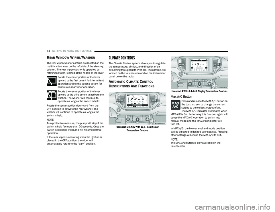
Uconnect 5/5 NAV With 10.1–inch Display
Temperature Controls Uconnect 4 With 8.4–inch Display Temperature Controls
Max A/C Button
Press and release the MAX A/C button on
the touchscreen to change the current
setting to the coldest output of air.
The MAX A/C indicator illuminates when
MAX A/C is ON. Performing this function again will
cause the MAX A/C operation to switch into
manual mode and the MAX A/C indicator will
turn off.
In MAX A/C, the blower level and mode position
can be adjusted to desired user settings. Pressing
other settings will cause the MAX A/C to exit.
NOTE:The MAX A/C button is only available on the
touchscreen.
22_WD_OM_EN_USC_t.book Page 54
Page 57 of 332
GETTING TO KNOW YOUR VEHICLE55
(Continued)
A/C Button
Press and release this button on the
touchscreen to change the current
setting. The A/C indicator illuminates
when A/C is on.
The Air Conditioning (A/C) button allows the
operator to manually activate or deactivate the air
conditioning system. When the air conditioning
system is turned on, cool dehumidified air will flow
through the outlets into the cabin.
NOTE:If fog or mist appears on the windshield or side
glass, select Defrost mode and increase blower
speed if needed. If your air conditioning perfor -
mance seems lower than expected, check the front
of the A/C condenser (located in front of the
radiator), for an accumulation of dirt or insects.
Clean with a gentle water spray from the front of
the radiator and through the condenser.
Recirculation Button
Press and release this button to change
the system between recirculation mode
and outside air mode. The Recirculation
indicator and the A/C indicator illuminate
when the Recirculation button is pressed.
Recirculation can be used when outside conditions
such as smoke, odors, dust, or high humidity are
present. Recirculation can be used in all modes.
Recirculation may be unavailable (button on the touchscreen greyed out) if conditions exist that
could create fogging on the inside of the
windshield. The A/C can be deselected manually
without disturbing the mode control selection.
Continuous use of Recirculation mode may make
the inside air stuffy and window fogging may occur.
Extended use of this mode is not recommended.
Recirculation mode may automatically adjust to
optimize customer experience for warming,
cooling, dehumidification, etc.
AUTO Button
Press and release this button on the
touchscreen, or push the button on the
faceplate, to change the current setting.
The AUTO button automatically controls
the interior cabin temperature by adjusting
distribution and amount of airflow. Air Conditioning
(A/C) may be active during AUTO operation to
improve performance. Performing this function will
cause the system to switch between manual mode
and automatic modes. AUTO mode is highly
recommended for efficiency Ú page 60.
Front Defrost Button
Press and release the touchscreen
button, or push and release the
button on the faceplate, to change the
current airflow setting to Defrost mode.
The Front Defrost indicator illuminates when
the Front Defrost is on. Air comes from the
windshield and side window demist outlets. When the defrost button is selected, the blower
level may increase. Use Defrost mode with
maximum temperature settings for best
windshield and side window defrosting and
defogging. When toggling the Front Defrost mode
button, the climate system will return to the
previous setting.
Rear Defrost Button
Press and release the button on the
touchscreen, or push and release the
button on the faceplate, to turn on the
rear window defroster and the heated
outside mirrors (if equipped). The Rear Defrost
indicator illuminates when the rear window
defroster is on. The rear window defroster
automatically turns off after 10 minutes.
CAUTION!
Failure to follow these cautions can cause
damage to the heating elements:
Use care when washing the inside of the rear
window. Do not use abrasive window cleaners
on the interior surface of the window. Use a
soft cloth and a mild washing solution, wiping
parallel to the heating elements. Labels can
be peeled off after soaking with warm water.
2
22_WD_OM_EN_USC_t.book Page 55
Page 62 of 332
60GETTING TO KNOW YOUR VEHICLE
Rear Lock
Pressing the Rear Temperature Lock button on the
Uconnect touchscreen, illuminates a lock symbol
in the rear display. The rear temperature and air
source are controlled from the front Uconnect
system.
Rear second row occupants can only adjust the
rear ATC control when the Rear Temperature Lock
button is turned off.
The rear ATC is located in the headliner, near the
center of the vehicle.
Press the Rear Temperature Lock button on the
Uconnect touchscreen. This turns off the Rear
Temperature Lock icon in the rear temperature
knob.
Rotate the Rear Blower, Rear Temperature and
the Rear Mode Control knobs to suit your
comfort needs.
ATC is selected by adjusting the rear blower
knob counterclockwise to AUTO.
Once the desired temperature is displayed, the
ATC System will automatically achieve and
maintain that comfort level. When the system is
set up for your comfort level, it is not necessary to
change the settings. You will experience the
greatest efficiency by simply allowing the system to
function automatically.
AUTOMATIC TEMPERATURE CONTROL
(ATC)
Automatic Operation
1. Push the AUTO button on the front Automatic
Temperature Control (ATC) Panel and the
word “AUTO” will illuminate in the front ATC
display, along with two temperatures for the
driver and front passenger. The system will
then automatically regulate the amount of
airflow.
2. Adjust the temperature you would like the system to maintain, by adjusting the driver,
passenger, and rear temperatures. Once the
desired temperature is displayed, the system
will achieve and automatically maintain that
comfort level.
3. When the system is set up for your comfort level, it is not necessary to change the
settings. You will experience the greatest
efficiency by simply allowing the system to
function automatically.
NOTE:It is not necessary to move the temperature
settings. The system automatically adjusts the
temperature, mode and fan speed to provide
comfort as quickly as possible.
To provide you with maximum comfort in the
automatic mode, during cold start-ups, the blower fan will remain on low until the engine warms up.
The fan will engage immediately if the Defrost
mode is selected, or by changing the front blower
knob setting.
Manual Operation Override
This system offers a full complement of manual
override features. The AUTO symbol in the front
ATC display will be turned off when the system is
being used in the manual mode.
NOTE:The system will not automatically sense the
presence of fog, mist or ice on the windshield.
Defrost mode must be manually selected to clear
the windshield and side glass.
CLIMATE VOICE RECOGNITION
Adjust vehicle temperatures hands-free and keep
everyone comfortable while you keep moving
ahead.
Push the VR button on the steering wheel. After the
beep, say one of the following commands:
“
Set driver temperature to 70 degrees ”
“Set passenger temperature to 70 degrees ”
Did you know: Voice Command for Climate may
only be used to adjust the interior temperature of
your vehicle. Voice Command will not work to
adjust the heated seats or steering wheel if
equipped.
22_WD_OM_EN_USC_t.book Page 60
Page 63 of 332
GETTING TO KNOW YOUR VEHICLE61
OPERATING TIPS
Refer to the chart at the end of this section for
suggested control settings for various weather
conditions.
Summer Operation
The engine cooling system must be protected with
a high-quality antifreeze coolant to provide proper
corrosion protection and to protect against engine
overheating. A solution of 50% OAT (Organic
Additive Technology) coolant that meets the
requirements of FCA Material Standard MS.90032
and 50% water is recommended Úpage 312.
Winter Operation
To ensure the best possible heater and defroster
performance, make sure the engine cooling
system is functioning properly and the proper
amount, type, and concentration of coolant is
used. Use of the Air Recirculation mode during
Winter months is not recommended, because it
may cause window fogging.
Vacation/Storage
For information on maintaining the Climate Control
system when the vehicle is being stored for an
extended period of time, see Úpage 304.
Window Fogging
Interior fogging on the windshield can be quickly
removed by turning the mode selector to Defrost.
The Defrost/Floor mode can be used to maintain a
clear windshield and provide sufficient heating.
If side window fogging becomes objectionable,
increase blower speed to improve airflow and
clearing of the side windows. Vehicle windows tend
to fog on the inside in mild but rainy or humid
weather.
NOTE:
Recirculate without A/C should not be used for
long periods, as fogging may occur.
Automatic Temperature Controls (ATC) will auto -
matically adjust the climate control settings to
reduce or eliminate window fogging on the front
windshield. When this occurs, recirculation will
be unavailable.
Outside Air Intake
Make sure the air intake, located directly in front of
the windshield, is free of obstructions, such as
leaves. Leaves collected in the air intake may
reduce airflow, and if they enter the air distribution
box, they could plug the water drains. In Winter
months, make sure the air intake is clear of ice,
slush, and snow.
Cabin Air Filter
The Climate Control system filters out dust and
pollen from the air. Contact an authorized dealer to
service your cabin air filter, and to have it replaced
when needed Ú page 262.
Stop/Start System — If Equipped
While in an Autostop, the Climate Control system
may automatically adjust airflow to maintain cabin
comfort. Customer settings will be maintained
upon return to an engine running condition.
CAUTION!
Interior air enters the Rear Automatic
Temperature Control system through an intake
grille, located in the right side trim panel behind
the third row seats. The heater outlets are
located in the right side trim panel, just behind
the passenger second row door. Do not block or
place objects directly in front of the inlet grille or
heater outlets. The electrical system could
overload causing damage to the blower motor.
2
22_WD_OM_EN_USC_t.book Page 61
Page 74 of 332
72GETTING TO KNOW YOUR VEHICLE
OPENING AND CLOSING THE SUNROOF
Express Open/Close
Push the switch rearward and release it within
one-half second; the sunroof and sunshade will
open automatically and stop at full open position.
Push the switch forward and release it within
one-half second and the sunroof will close
automatically from any position.
During Express Open or Express Close operation,
any movement of the sunshade switch will stop the
shade.
Manual Open/Close
Push and hold the switch rearward; the sunroof
and sunshade will open and automatically stop at
full open position.
Push and hold the switch forward and the sunroof
will close from any position and stop at a full closed
position.
Any release of the switch during open or close
operation will stop the sunroof movement. The
sunroof will remain in a partially opened position
until the switch is operated and held again. Venting The Sunroof
Push and release the "Vent" button within one-half
second and the sunroof will open to the vent
position. This is called “Express Vent”, and it will
occur regardless of sunroof position. During
Express Vent operation, any movement of the
switch will stop the sunroof.
SUNSHADE OPERATION
The sunshade can be opened manually. However,
the sunshade will open automatically as the
sunroof opens.
NOTE:The sunshade cannot be closed if the sunroof is
open.
PINCH PROTECT FEATURE
This feature will detect an obstruction in the
closing of the sunroof during the Express Close
operation. If an obstruction in the path of the
sunroof is detected, the sunroof will automatically
retract. Remove the obstruction if this occurs.
NOTE:If three consecutive sunroof close attempts result
in Pinch Protect reversals, Pinch Protect will
disable and the sunroof must be closed in Manual
Mode.
SUNROOF MAINTENANCE
Use only a non-abrasive cleaner and a soft cloth to
clean the glass panel. Periodically check for and
clear out any debris that may have collected in
the tracks.
IGNITION OFF OPERATION
NOTE:
The power sunroof switch can remain active in
Accessory Delay for up to approximately
10 minutes after the vehicle’s ignition is placed
to the OFF position. Opening either front door
will cancel this feature.
This feature is programmable using the
Uconnect system Ú
page 156.
WARNING!
There is no anti-pinch protection when the sunroof
is almost closed. To avoid personal injury be sure
to clear your arms, hands, fingers and all objects
from the top’s path before closing.
22_WD_OM_EN_USC_t.book Page 72
Page 75 of 332
GETTING TO KNOW YOUR VEHICLE73
HOOD
OPENING THE HOOD
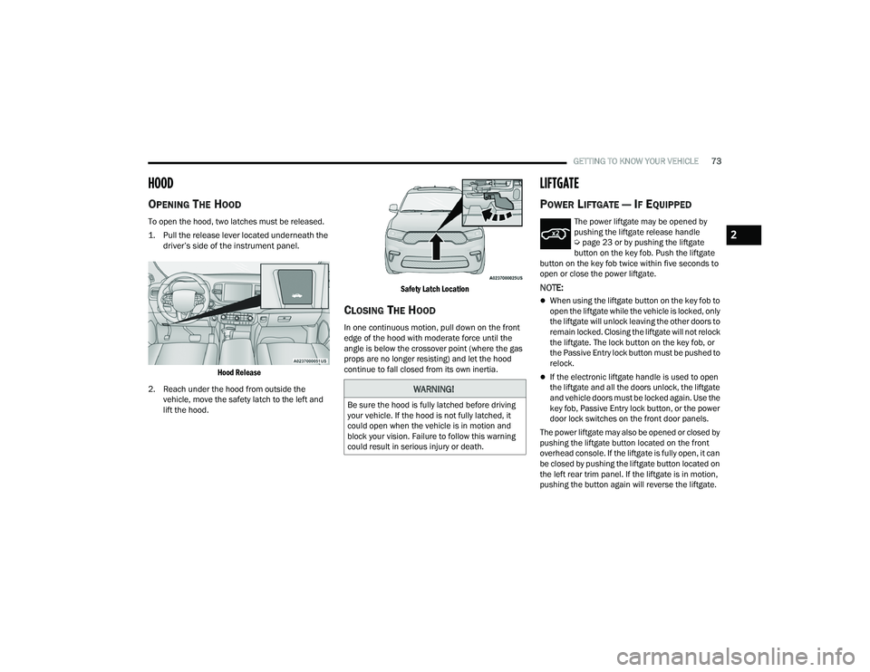
To open the hood, two latches must be released.
1. Pull the release lever located underneath the
driver’s side of the instrument panel.
Hood Release
2. Reach under the hood from outside the vehicle, move the safety latch to the left and
lift the hood.
Safety Latch Location
CLOSING THE HOOD
In one continuous motion, pull down on the front
edge of the hood with moderate force until the
angle is below the crossover point (where the gas
props are no longer resisting) and let the hood
continue to fall closed from its own inertia.
LIFTGATE
POWER LIFTGATE — IF EQUIPPED
The power liftgate may be opened by
pushing the liftgate release handle
Ú
page 23 or by pushing the liftgate
button on the key fob. Push the liftgate
button on the key fob twice within five seconds to
open or close the power liftgate.
NOTE:
When using the liftgate button on the key fob to
open the liftgate while the vehicle is locked, only
the liftgate will unlock leaving the other doors to
remain locked. Closing the liftgate will not relock
the liftgate. The lock button on the key fob, or
the Passive Entry lock button must be pushed to
relock.
If the electronic liftgate handle is used to open
the liftgate and all the doors unlock, the liftgate
and vehicle doors must be locked again. Use the
key fob, Passive Entry lock button, or the power
door lock switches on the front door panels.
The power liftgate may also be opened or closed by
pushing the liftgate button located on the front
overhead console. If the liftgate is fully open, it can
be closed by pushing the liftgate button located on
the left rear trim panel. If the liftgate is in motion,
pushing the button again will reverse the liftgate.
WARNING!
Be sure the hood is fully latched before driving
your vehicle. If the hood is not fully latched, it
could open when the vehicle is in motion and
block your vision. Failure to follow this warning
could result in serious injury or death.
2
22_WD_OM_EN_USC_t.book Page 73
Page 90 of 332
88GETTING TO KNOW YOUR INSTRUMENT PANEL
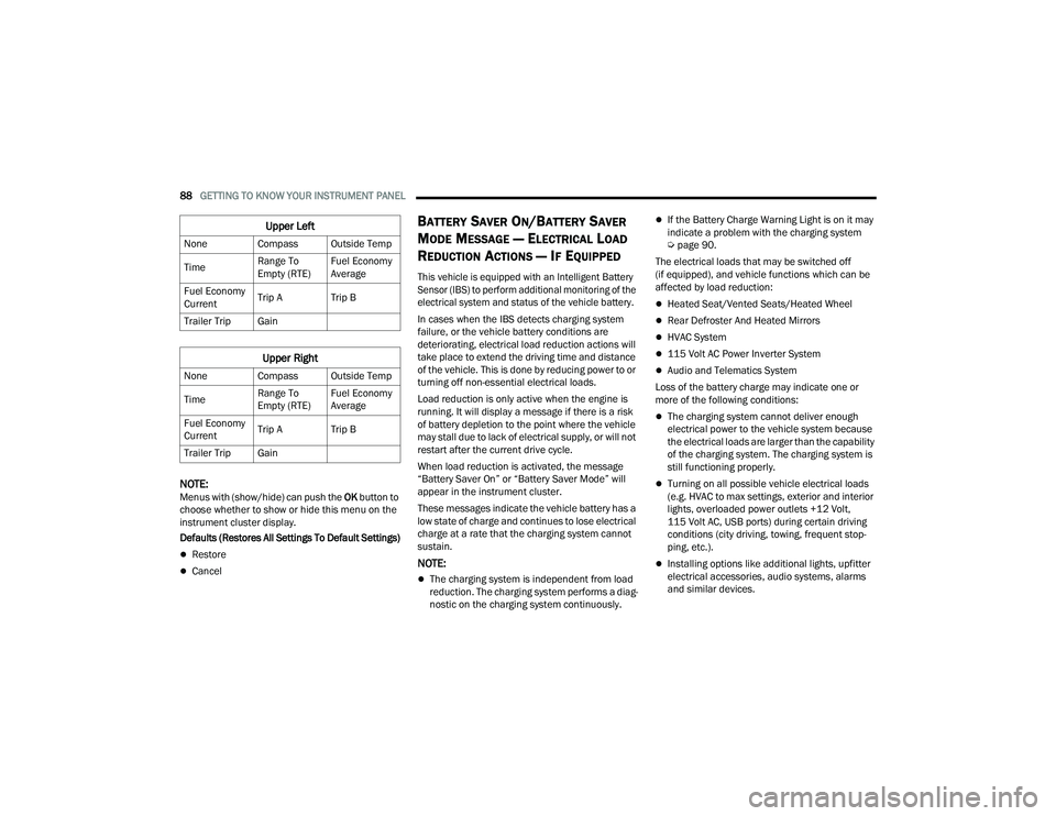
NOTE:Menus with (show/hide) can push the OK button to
choose whether to show or hide this menu on the
instrument cluster display.
Defaults (Restores All Settings To Default Settings)
Restore
Cancel
BATTERY SAVER ON/BATTERY SAVER
M
ODE MESSAGE — ELECTRICAL LOAD
R
EDUCTION ACTIONS — IF EQUIPPED
This vehicle is equipped with an Intelligent Battery
Sensor (IBS) to perform additional monitoring of the
electrical system and status of the vehicle battery.
In cases when the IBS detects charging system
failure, or the vehicle battery conditions are
deteriorating, electrical load reduction actions will
take place to extend the driving time and distance
of the vehicle. This is done by reducing power to or
turning off non-essential electrical loads.
Load reduction is only active when the engine is
running. It will display a message if there is a risk
of battery depletion to the point where the vehicle
may stall due to lack of electrical supply, or will not
restart after the current drive cycle.
When load reduction is activated, the message
“Battery Saver On” or “Battery Saver Mode” will
appear in the instrument cluster.
These messages indicate the vehicle battery has a
low state of charge and continues to lose electrical
charge at a rate that the charging system cannot
sustain.
NOTE:
The charging system is independent from load
reduction. The charging system performs a diag -
nostic on the charging system continuously.
If the Battery Charge Warning Light is on it may
indicate a problem with the charging system
Ú page 90.
The electrical loads that may be switched off
(if equipped), and vehicle functions which can be
affected by load reduction:
Heated Seat/Vented Seats/Heated Wheel
Rear Defroster And Heated Mirrors
HVAC System
115 Volt AC Power Inverter System
Audio and Telematics System
Loss of the battery charge may indicate one or
more of the following conditions:
The charging system cannot deliver enough
electrical power to the vehicle system because
the electrical loads are larger than the capability
of the charging system. The charging system is
still functioning properly.
Turning on all possible vehicle electrical loads
(e.g. HVAC to max settings, exterior and interior
lights, overloaded power outlets +12 Volt,
115 Volt AC, USB ports) during certain driving
conditions (city driving, towing, frequent stop -
ping, etc.).
Installing options like additional lights, upfitter
electrical accessories, audio systems, alarms
and similar devices.
Upper Left
None Compass Outside Temp
Time Range To
Empty (RTE)Fuel Economy
Average
Fuel Economy
Current Trip A Trip B
Trailer Trip Gain
Upper Right
None Compass Outside Temp
Time Range To
Empty (RTE)Fuel Economy
Average
Fuel Economy
Current Trip A Trip B
Trailer Trip Gain
22_WD_OM_EN_USC_t.book Page 88
Page 91 of 332
GETTING TO KNOW YOUR INSTRUMENT PANEL89
Unusual driving cycles (short trips separated by
long parking periods).
The vehicle was parked for an extended period
of time (weeks, months).
The battery was recently replaced and was not
charged completely.
The battery was discharged by an electrical load
left on when the vehicle was parked.
The battery was used for an extended period
with the engine not running to supply radio,
lights, chargers, +12 Volt portable appliances
like vacuum cleaners, game consoles and
similar devices.
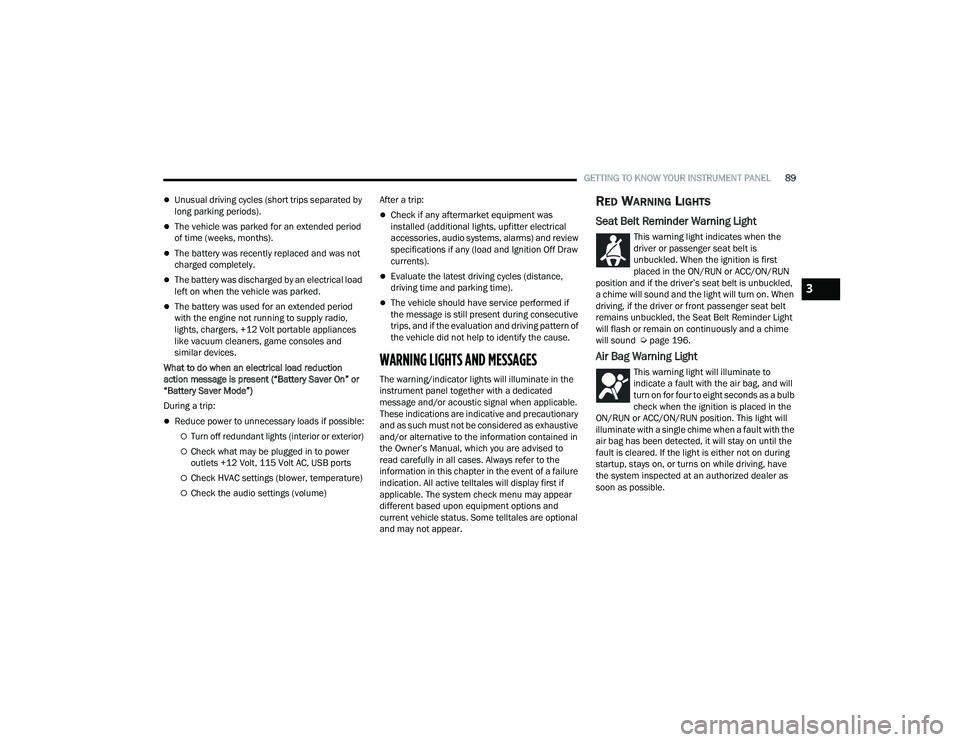
What to do when an electrical load reduction
action message is present (“Battery Saver On” or
“Battery Saver Mode”)
During a trip:
Reduce power to unnecessary loads if possible:
Turn off redundant lights (interior or exterior)
Check what may be plugged in to power
outlets +12 Volt, 115 Volt AC, USB ports
Check HVAC settings (blower, temperature)
Check the audio settings (volume) After a trip:
Check if any aftermarket equipment was
installed (additional lights, upfitter electrical
accessories, audio systems, alarms) and review
specifications if any (load and Ignition Off Draw
currents).
Evaluate the latest driving cycles (distance,
driving time and parking time).
The vehicle should have service performed if
the message is still present during consecutive
trips, and if the evaluation and driving pattern of
the vehicle did not help to identify the cause.
WARNING LIGHTS AND MESSAGES
The warning/indicator lights will illuminate in the
instrument panel together with a dedicated
message and/or acoustic signal when applicable.
These indications are indicative and precautionary
and as such must not be considered as exhaustive
and/or alternative to the information contained in
the Owner’s Manual, which you are advised to
read carefully in all cases. Always refer to the
information in this chapter in the event of a failure
indication. All active telltales will display first if
applicable. The system check menu may appear
different based upon equipment options and
current vehicle status. Some telltales are optional
and may not appear.
RED WARNING LIGHTS
Seat Belt Reminder Warning Light
This warning light indicates when the
driver or passenger seat belt is
unbuckled. When the ignition is first
placed in the ON/RUN or ACC/ON/RUN
position and if the driver’s seat belt is unbuckled,
a chime will sound and the light will turn on. When
driving, if the driver or front passenger seat belt
remains unbuckled, the Seat Belt Reminder Light
will flash or remain on continuously and a chime
will sound Ú page 196.
Air Bag Warning Light
This warning light will illuminate to
indicate a fault with the air bag, and will
turn on for four to eight seconds as a bulb
check when the ignition is placed in the
ON/RUN or ACC/ON/RUN position. This light will
illuminate with a single chime when a fault with the
air bag has been detected, it will stay on until the
fault is cleared. If the light is either not on during
startup, stays on, or turns on while driving, have
the system inspected at an authorized dealer as
soon as possible.
3
22_WD_OM_EN_USC_t.book Page 89