climate control DODGE DURANGO 2022 User Guide
[x] Cancel search | Manufacturer: DODGE, Model Year: 2022, Model line: DURANGO, Model: DODGE DURANGO 2022Pages: 332, PDF Size: 19.82 MB
Page 62 of 332
60GETTING TO KNOW YOUR VEHICLE
Rear Lock
Pressing the Rear Temperature Lock button on the
Uconnect touchscreen, illuminates a lock symbol
in the rear display. The rear temperature and air
source are controlled from the front Uconnect
system.
Rear second row occupants can only adjust the
rear ATC control when the Rear Temperature Lock
button is turned off.
The rear ATC is located in the headliner, near the
center of the vehicle.
Press the Rear Temperature Lock button on the
Uconnect touchscreen. This turns off the Rear
Temperature Lock icon in the rear temperature
knob.
Rotate the Rear Blower, Rear Temperature and
the Rear Mode Control knobs to suit your
comfort needs.
ATC is selected by adjusting the rear blower
knob counterclockwise to AUTO.
Once the desired temperature is displayed, the
ATC System will automatically achieve and
maintain that comfort level. When the system is
set up for your comfort level, it is not necessary to
change the settings. You will experience the
greatest efficiency by simply allowing the system to
function automatically.
AUTOMATIC TEMPERATURE CONTROL
(ATC)
Automatic Operation
1. Push the AUTO button on the front Automatic
Temperature Control (ATC) Panel and the
word “AUTO” will illuminate in the front ATC
display, along with two temperatures for the
driver and front passenger. The system will
then automatically regulate the amount of
airflow.
2. Adjust the temperature you would like the system to maintain, by adjusting the driver,
passenger, and rear temperatures. Once the
desired temperature is displayed, the system
will achieve and automatically maintain that
comfort level.
3. When the system is set up for your comfort level, it is not necessary to change the
settings. You will experience the greatest
efficiency by simply allowing the system to
function automatically.
NOTE:It is not necessary to move the temperature
settings. The system automatically adjusts the
temperature, mode and fan speed to provide
comfort as quickly as possible.
To provide you with maximum comfort in the
automatic mode, during cold start-ups, the blower fan will remain on low until the engine warms up.
The fan will engage immediately if the Defrost
mode is selected, or by changing the front blower
knob setting.
Manual Operation Override
This system offers a full complement of manual
override features. The AUTO symbol in the front
ATC display will be turned off when the system is
being used in the manual mode.
NOTE:The system will not automatically sense the
presence of fog, mist or ice on the windshield.
Defrost mode must be manually selected to clear
the windshield and side glass.
CLIMATE VOICE RECOGNITION
Adjust vehicle temperatures hands-free and keep
everyone comfortable while you keep moving
ahead.
Push the VR button on the steering wheel. After the
beep, say one of the following commands:
“
Set driver temperature to 70 degrees ”
“Set passenger temperature to 70 degrees ”
Did you know: Voice Command for Climate may
only be used to adjust the interior temperature of
your vehicle. Voice Command will not work to
adjust the heated seats or steering wheel if
equipped.
22_WD_OM_EN_USC_t.book Page 60
Page 63 of 332
GETTING TO KNOW YOUR VEHICLE61
OPERATING TIPS
Refer to the chart at the end of this section for
suggested control settings for various weather
conditions.
Summer Operation
The engine cooling system must be protected with
a high-quality antifreeze coolant to provide proper
corrosion protection and to protect against engine
overheating. A solution of 50% OAT (Organic
Additive Technology) coolant that meets the
requirements of FCA Material Standard MS.90032
and 50% water is recommended Úpage 312.
Winter Operation
To ensure the best possible heater and defroster
performance, make sure the engine cooling
system is functioning properly and the proper
amount, type, and concentration of coolant is
used. Use of the Air Recirculation mode during
Winter months is not recommended, because it
may cause window fogging.
Vacation/Storage
For information on maintaining the Climate Control
system when the vehicle is being stored for an
extended period of time, see Úpage 304.
Window Fogging
Interior fogging on the windshield can be quickly
removed by turning the mode selector to Defrost.
The Defrost/Floor mode can be used to maintain a
clear windshield and provide sufficient heating.
If side window fogging becomes objectionable,
increase blower speed to improve airflow and
clearing of the side windows. Vehicle windows tend
to fog on the inside in mild but rainy or humid
weather.
NOTE:
Recirculate without A/C should not be used for
long periods, as fogging may occur.
Automatic Temperature Controls (ATC) will auto -
matically adjust the climate control settings to
reduce or eliminate window fogging on the front
windshield. When this occurs, recirculation will
be unavailable.
Outside Air Intake
Make sure the air intake, located directly in front of
the windshield, is free of obstructions, such as
leaves. Leaves collected in the air intake may
reduce airflow, and if they enter the air distribution
box, they could plug the water drains. In Winter
months, make sure the air intake is clear of ice,
slush, and snow.
Cabin Air Filter
The Climate Control system filters out dust and
pollen from the air. Contact an authorized dealer to
service your cabin air filter, and to have it replaced
when needed Ú page 262.
Stop/Start System — If Equipped
While in an Autostop, the Climate Control system
may automatically adjust airflow to maintain cabin
comfort. Customer settings will be maintained
upon return to an engine running condition.
CAUTION!
Interior air enters the Rear Automatic
Temperature Control system through an intake
grille, located in the right side trim panel behind
the third row seats. The heater outlets are
located in the right side trim panel, just behind
the passenger second row door. Do not block or
place objects directly in front of the inlet grille or
heater outlets. The electrical system could
overload causing damage to the blower motor.
2
22_WD_OM_EN_USC_t.book Page 61
Page 69 of 332
GETTING TO KNOW YOUR VEHICLE67
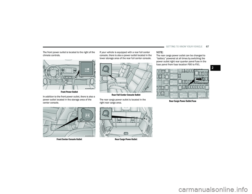
The front power outlet is located to the right of the
climate controls.
Front Power Outlet
In addition to the front power outlet, there is also a
power outlet located in the storage area of the
center console.
Front Center Console Outlet
If your vehicle is equipped with a rear full center
console, there is also a power outlet located in the
lower storage area of the rear full center console.
Rear Full Center Console Outlet
The rear cargo power outlet is located in the
right rear cargo area.
Rear Cargo Power Outlet
NOTE:The rear cargo power outlet can be changed to
“battery” powered at all times by switching the
power outlet right rear quarter panel fuse in the
fuse panel from fuse location F90 to F91.
Rear Cargo Power Outlet Fuse
2
22_WD_OM_EN_USC_t.book Page 67
Page 76 of 332
74GETTING TO KNOW YOUR VEHICLE
(Continued)
When the liftgate button on the key fob is pushed
two times, the turn signals will flash to signal that
the liftgate is opening or closing (if Flash Lamps
with Lock is enabled in the Uconnect settings), and
the liftgate chime will be audible. The chime can be
turned on or off through the Uconnect Settings
Ú
page 156.
NOTE:
In the event of a power malfunction to the lift -
gate, an emergency liftgate latch release can be
used to open the liftgate. The emergency liftgate
latch release can be accessed through a snap-in
cover located on the liftgate trim panel.
If liftgate is left open for an extended period of
time, the liftgate may need to be closed manu -
ally to reset power liftgate functionality.
NOTE:
The power liftgate buttons will not operate if the
vehicle is in gear or the vehicle speed is above
0 mph (0 km/h).
The power liftgate will not operate in tempera -
tures below −22°F (−30°C) or temperatures
above 150°F (65°C). Be sure to remove any
buildup of snow or ice from the liftgate before
pushing any of the power liftgate switches.
If anything obstructs the power liftgate while it is
closing or opening, the liftgate will automatically
reverse to the closed or open position. After
multiple obstructions in the same cycle, the lift -
gate will automatically stop and must be opened
or closed manually.
There are also pinch sensors attached to the
side of the liftgate. Light pressure anywhere
along these strips will cause the liftgate to
return to the open position.
If the liftgate is only partially open, push the lift -
gate button on the key fob twice to operate the
liftgate.
If the liftgate release handle is pushed while the
power liftgate is opening, the liftgate motor will
disengage to allow manual operation.
CARGO AREA FEATURES
Cargo Storage
There is a removable storage bin located on the
left side of the rear cargo area.
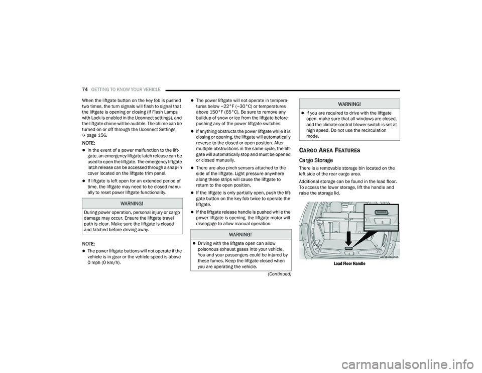
Additional storage can be found in the load floor.
To access the lower storage, lift the handle and
raise the storage lid.
Load Floor Handle
WARNING!
During power operation, personal injury or cargo
damage may occur. Ensure the liftgate travel
path is clear. Make sure the liftgate is closed
and latched before driving away.
WARNING!
Driving with the liftgate open can allow
poisonous exhaust gases into your vehicle.
You and your passengers could be injured by
these fumes. Keep the liftgate closed when
you are operating the vehicle.
If you are required to drive with the liftgate
open, make sure that all windows are closed,
and the climate control blower switch is set at
high speed. Do not use the recirculation
mode.
WARNING!
22_WD_OM_EN_USC_t.book Page 74
Page 104 of 332
102STARTING AND OPERATING
(Continued)
4. If the engine fails to start after eight attempts,
allow the starter to cool for at least
10 minutes, then repeat the procedure.
IF ENGINE FAILS TO START
If the engine fails to start after you have followed
the “Normal Starting” procedure and the vehicle
has not experienced an extended park condition
as defined previously, it may be flooded. Push the
accelerator pedal all the way to the floor and hold
it there while the engine is cranking. This should
clear any excess fuel in case the engine is flooded.
The starter motor will engage automatically, run for
10 seconds, and then disengage. Once this occurs,
release the accelerator pedal and brake pedal,
wait 10 to 15 seconds, then repeat the “Normal
Starting” procedure.
COLD WEATHER OPERATION
(BELOW –22°F OR −30°C)
To ensure reliable starting at these temperatures,
use of an externally powered electric engine block
heater (available from an authorized dealer) is
recommended.
AFTER STARTING
The idle speed is controlled automatically, and it
will decrease as the engine warms up.
ENGINE BREAK-IN RECOMMENDATIONS
A long break-in period is not required for the engine
and drivetrain (transmission and axle) in your
vehicle.
Drive moderately during the first 300 miles
(500 km). After the initial 60 miles (100 km),
speeds up to 50 or 55 mph (80 or 90 km/h) are
desirable.
Brief full-throttle acceleration within the limits of
local traffic laws contributes to a good break-in.
Wide-open throttle acceleration in low gear can be
detrimental and should be avoided.
The engine oil installed in the engine at the factory
is a high-quality energy conserving type lubricant.
Oil changes should be consistent with anticipated
climate conditions under which vehicle operations
will occur. For the recommended viscosity and
quality grades see Ú page 312.
CAUTION!
To prevent damage to the starter, do not crank
continuously for more than 10 seconds at a
time. Wait 10 to 15 seconds before trying again.
WARNING!
Never pour fuel or other flammable liquid into
the throttle body air inlet opening in an
attempt to start the vehicle. This could result
in flash fire causing serious personal injury.
Do not attempt to push or tow your vehicle to
get it started. Vehicles equipped with an auto -
matic transmission cannot be started this
way. Unburned fuel could enter the catalytic
converter and once the engine has started,
ignite and damage the converter and vehicle.
If the vehicle has a discharged battery,
booster cables may be used to obtain a start
from a booster battery or the battery in
another vehicle. This type of start can be
dangerous if done improperly Ú page 246.
CAUTION!
To prevent damage to the starter, do not
continuously crank the engine for more than
10 seconds at a time. Wait 10 to 15 seconds
before trying again.
WARNING!
CAUTION!
Never use Non-Detergent Oil or Straight Mineral
Oil in the engine or damage may result.
22_WD_OM_EN_USC_t.book Page 102
Page 236 of 332
234SAFETY
(Continued)
Lights
Have someone observe the operation of brake
lights and exterior lights while you work the
controls. Check turn signal and high beam
indicator lights on the instrument panel.
Door Latches
Check for proper closing, latching, and locking.
Fluid Leaks
Check area under the vehicle after overnight
parking for fuel, coolant, oil, or other fluid leaks.
Also, if gasoline fumes are detected or if fuel or
brake fluid leaks are suspected, the cause should
be located and corrected immediately.
EXHAUST GAS
The best protection against carbon monoxide entry
into the vehicle body is a properly maintained
engine exhaust system.
Whenever a change is noticed in the sound of the
exhaust system, when exhaust fumes can be
detected inside the vehicle, or when the underside
or rear of the vehicle is damaged, have an
authorized dealer inspect the complete exhaust
system and adjacent body areas for broken,
damaged, deteriorated, or mispositioned parts.
Open seams or loose connections could permit
exhaust fumes to seep into the passenger
compartment. In addition, inspect the exhaust
system each time the vehicle is raised for
lubrication or oil change. Replace as required.
CARBON MONOXIDE WARNINGS
WARNING!
Exhaust gases can injure or kill. They contain
carbon monoxide (CO), which is colorless and
odorless. Breathing it can make you
unconscious and can eventually poison you.
To avoid breathing (CO), follow these safety tips:
Do not run the engine in a closed garage or in
confined areas any longer than needed to
move your vehicle in or out of the area.
If you are required to drive with the trunk/lift -
gate/rear doors open, make sure that all
windows are closed and the climate control
BLOWER switch is set at high speed. DO NOT
use the recirculation mode.
If it is necessary to sit in a parked vehicle with
the engine running, adjust your heating or
cooling controls to force outside air into the
vehicle. Set the blower at high speed.
WARNING!
WARNING!
Carbon monoxide (CO) in exhaust gases is
deadly. Follow the precautions below to prevent
carbon monoxide poisoning:
Do not inhale exhaust gases. They contain
carbon monoxide, a colorless and odorless
gas, which can kill. Never run the engine in a
closed area, such as a garage, and never sit in
a parked vehicle with the engine running for
an extended period. If the vehicle is stopped in
an open area with the engine running for more
than a short period, adjust the ventilation
system to force fresh, outside air into the
vehicle.
Guard against carbon monoxide with proper
maintenance. Have the exhaust system
inspected every time the vehicle is raised.
Have any abnormal conditions repaired
promptly. Until repaired, drive with all side
windows fully open.
22_WD_OM_EN_USC_t.book Page 234
Page 237 of 332
235
IN CASE OF EMERGENCY
HAZARD WARNING FLASHERS
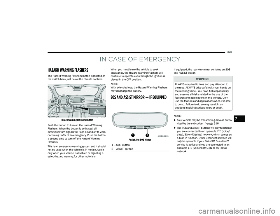
The Hazard Warning Flashers button is located on
the switch bank just below the climate controls.
Hazard Warning Flashers Button
Push the button to turn on the Hazard Warning
Flashers. When the button is activated, all
directional turn signals will flash on and off to warn
oncoming traffic of an emergency. Push the button
a second time to turn off the Hazard Warning
Flashers.
This is an emergency warning system and it should
not be used when the vehicle is in motion. Use it
only when your vehicle is disabled or signaling a
safety hazard warning for other motorists. When you must leave the vehicle to seek
assistance, the Hazard Warning Flashers will
continue to operate even though the ignition is
placed in the OFF position.
NOTE:With extended use, the Hazard Warning Flashers
may discharge the battery.
SOS AND ASSIST MIRROR — IF EQUIPPED
Assist And SOS Mirror
If equipped, the rearview mirror contains an SOS
and ASSIST button.
NOTE:
Your vehicle may be transmitting data as autho
-
rized by the subscriber Ú page 316.
The SOS and ASSIST buttons will only function if
you are connected to an operable LTE (voice/
data), 3G or 4G (data) network, which comes as
a built in function. Other Uconnect services will
only be operable if your SiriusXM Guardian™
service is active and you are connected to an
operable LTE (voice/data), 3G or 4G (data)
network.
1 — SOS Button
2 — ASSIST Button
WARNING!
ALWAYS obey traffic laws and pay attention to
the road. ALWAYS drive safely with your hands on
the steering wheel. You have full responsibility
and assume all risks related to the use of the
features and applications in this vehicle. Only
use the features and applications when it is safe
to do so. Failure to do so may result in an
accident involving serious injury or death.
7
22_WD_OM_EN_USC_t.book Page 235
Page 305 of 332
SERVICING AND MAINTENANCE303
DEPARTMENT OF TRANSPORTATION
UNIFORM TIRE QUALITY GRADES
The following tire grading categories
were established by the National
Highway Traffic Safety Administration.
The specific grade rating assigned by the
tire's manufacturer in each category is
shown on the sidewall of the tires on
your vehicle.
All passenger vehicle tires must conform
to Federal safety requirements in
addition to these grades.
TREADWEAR
The Treadwear grade is a comparative
rating, based on the wear rate of the tire
when tested under controlled conditions
on a specified government test course.
For example, a tire graded 150 would
wear one and one-half times as well on
the government course as a tire graded
100. The relative performance of tires
depends upon the actual conditions of
their use, however, and may depart
significantly from the norm due to variations in driving habits, service
practices, and differences in road
characteristics and climate.
TRACTION GRADES
The Traction grades, from highest to
lowest, are AA, A, B, and C. These grades
represent the tire's ability to stop on wet
pavement, as measured under
controlled conditions on specified
government test surfaces of asphalt and
concrete. A tire marked C may have poor
traction performance.
TEMPERATURE GRADES
The Temperature grades are A (the
highest), B, and C, representing the tire's
resistance to the generation of heat and
its ability to dissipate heat, when tested
under controlled conditions on a
specified indoor laboratory test wheel.
Sustained high temperature can cause
the material of the tire to degenerate
and reduce tire life, and excessive
temperature can lead to sudden tire
failure. The grade C corresponds to a
level of performance, which all
passenger vehicle tires must meet
under the Federal Motor Vehicle Safety
Standard No. 109. Grades B and A
represent higher levels of performance
on the laboratory test wheel, than the
minimum required by law.
WARNING!
The traction grade assigned to this tire is based
on straight-ahead braking traction tests, and
does not include acceleration, cornering,
hydroplaning, or peak traction characteristics.WARNING!
The temperature grade for this tire is
established for a tire that is properly inflated and
not overloaded. Excessive speed, underinflation,
or excessive loading, either separately or in
combination, can cause heat buildup and
possible tire failure.
8
22_WD_OM_EN_USC_t.book Page 303
Page 320 of 332
318 B
Battery
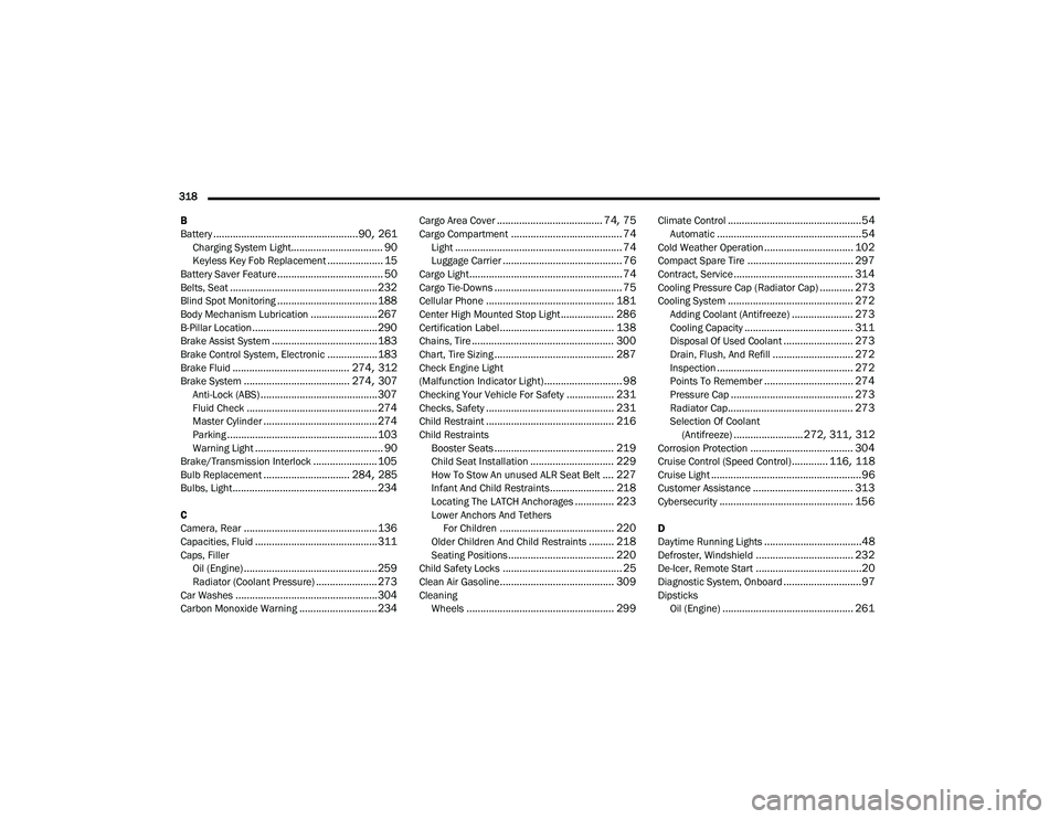
.................................................... 90, 261Charging System Light................................. 90Keyless Key Fob Replacement.................... 15Battery Saver Feature...................................... 50Belts, Seat..................................................... 232Blind Spot Monitoring.................................... 188Body Mechanism Lubrication........................ 267B-Pillar Location............................................. 290Brake Assist System...................................... 183Brake Control System, Electronic.................. 183Brake Fluid.......................................... 274, 312Brake System...................................... 274, 307Anti-Lock (ABS).......................................... 307Fluid Check............................................... 274Master Cylinder......................................... 274Parking...................................................... 103Warning Light.............................................. 90Brake/Transmission Interlock....................... 105Bulb Replacement............................... 284, 285Bulbs, Light.................................................... 234
C
Camera, Rear................................................ 136Capacities, Fluid............................................ 311Caps, Filler Oil (Engine)................................................ 259Radiator (Coolant Pressure)...................... 273Car Washes................................................... 304Carbon Monoxide Warning............................ 234
Cargo Area Cover...................................... 74, 75Cargo Compartment........................................ 74Light............................................................ 74Luggage Carrier........................................... 76Cargo Light....................................................... 74Cargo Tie-Downs.............................................. 75Cellular Phone.............................................. 181Center High Mounted Stop Light................... 286Certification Label......................................... 138Chains, Tire................................................... 300Chart, Tire Sizing........................................... 287Check Engine Light
(Malfunction Indicator Light)............................ 98Checking Your Vehicle For Safety................. 231Checks, Safety.............................................. 231Child Restraint.............................................. 216Child RestraintsBooster Seats........................................... 219Child Seat Installation.............................. 229How To Stow An unused ALR Seat Belt.... 227Infant And Child Restraints....................... 218Locating The LATCH Anchorages.............. 223Lower Anchors And TethersFor Children......................................... 220Older Children And Child Restraints......... 218Seating Positions...................................... 220Child Safety Locks........................................... 25Clean Air Gasoline......................................... 309CleaningWheels..................................................... 299
Climate Control................................................54Automatic....................................................54Cold Weather Operation................................ 102Compact Spare Tire...................................... 297Contract, Service........................................... 314Cooling Pressure Cap (Radiator Cap)............ 273Cooling System............................................. 272Adding Coolant (Antifreeze)...................... 273Cooling Capacity....................................... 311Disposal Of Used Coolant......................... 273Drain, Flush, And Refill............................. 272Inspection................................................. 272Points To Remember................................ 274Pressure Cap............................................ 273Radiator Cap............................................. 273Selection Of Coolant(Antifreeze)......................... 272, 311, 312Corrosion Protection..................................... 304Cruise Control (Speed Control)............. 116, 118Cruise Light......................................................96Customer Assistance.................................... 313Cybersecurity................................................ 156
D
Daytime Running Lights...................................48Defroster, Windshield................................... 232De-Icer, Remote Start......................................20Diagnostic System, Onboard............................97DipsticksOil (Engine)............................................... 261
22_WD_OM_EN_USC_t.book Page 318