tow DODGE DURANGO 2022 User Guide
[x] Cancel search | Manufacturer: DODGE, Model Year: 2022, Model line: DURANGO, Model: DODGE DURANGO 2022Pages: 332, PDF Size: 19.82 MB
Page 55 of 332
GETTING TO KNOW YOUR VEHICLE53
Intermittent Wipers
Use one of the four intermittent wiper settings
when weather conditions make a single wiping
cycle, with a variable delay between cycles,
desirable. At driving speeds above 10 mph
(16 km/h), the delay can be regulated from a
maximum of approximately 18 seconds between
cycles (first detent), to a cycle every one second
(fourth detent). If the vehicle is moving less than
10 mph (16 km/h), delay times will be doubled.
Windshield Washers
To use the washer, push on the end of the lever
(toward the steering wheel) and hold. If the lever is
pushed while in the intermittent setting, the wipers
will turn on and operate for several cycles after the
end of the lever is released, and then resume the
intermittent interval previously selected.
If the end of the lever is pushed while the wipers
are in the off position, the wipers will operate for
several cycles, then turn off.
NOTE:As a protective measure, the washer will stop if the
switch is held for more than 20 seconds. Once the
switch is released the washer will resume normal
operation. Mist
Rotate the end of the lever downward to the MIST
position and release for a single wiping cycle.
NOTE:The Mist feature does not activate the washer
pump; therefore, no washer fluid will be sprayed on
the windshield. The wash function must be used in
order to spray the windshield with washer fluid.
For information on wiper care and replacement,
see Ú
page 268.
RAIN SENSING WIPERS — IF EQUIPPED
This feature senses rain or snowfall on the
windshield and automatically activates the wipers.
Rotate the end of the multifunction lever to one of
four detent positions to activate this feature.
The sensitivity of the system can be adjusted with
the multifunction lever. Wiper delay position one is
the least sensitive, and wiper delay position four is
the most sensitive. Setting three is preferred by the average driver
during normal rain conditions.
NOTE:
The Rain Sensing feature will not operate when
the wiper switch is in the low or high-speed posi
-
tion.
The Rain Sensing feature may not function prop -
erly when ice, or dried salt water is present on
the windshield.
Use of Rain-X or products containing wax or sili-
cone may reduce Rain Sensing performance.
The Rain Sensing feature can be turned on and
off using the Uconnect system Ú page 156.
The Rain Sensing system has protection features
for the wiper blades and arms, and will not operate
under the following conditions:
Low Ambient Temperature — When the ignition
is first placed in the ON position, the Rain
Sensing system will not operate until the wiper
switch is moved, vehicle speed is greater than
3 mph (5 km/h), or the outside temperature is
greater than 32°F (0°C).
Transmission In NEUTRAL Position — When the
ignition is in the ON position, and the gear
selector is in NEUTRAL, the Rain Sensing system
will not operate until the wiper switch is moved,
vehicle speed is greater than 3 mph (5 km/h),
or the gear selector is moved out of NEUTRAL.
WARNING!
Sudden loss of visibility through the windshield
could lead to a collision. You might not see other
vehicles or other obstacles. To avoid sudden
icing of the windshield during freezing weather,
warm the windshield with the defroster before
and during windshield washer use.
2
22_WD_OM_EN_USC_t.book Page 53
Page 58 of 332
56GETTING TO KNOW YOUR VEHICLE
Driver And Passenger Temperature
Buttons
These buttons provide the driver and passenger
with independent temperature control.
Push the Up button on the faceplate or
press and slide the temperature bar
towards the red arrow button on
the touchscreen for warmer
temperature settings.
Push the Down button on the faceplate or
press and slide the temperature bar
towards the blue arrow button on
the touchscreen for cooler
temperature settings.
SYNC Button
Press the SYNC button on the
touchscreen to toggle the SYNC feature
on/off. The SYNC indicator illuminates
when SYNC is on. SYNC is used to
synchronize the front passenger temperature and rear passenger temperature, mode, and blower
settings with the driver temperature, mode, and
blower settings. Changing the front passenger
temperature or rear passenger temperature,
mode, and blower settings while in SYNC will
automatically exit this feature.
NOTE:The SYNC setting is only available on the touch
-
screen.
Blower Control
Blower Control is used to regulate the
amount of air forced through the Climate
Control system. There are seven blower
speeds available. Adjusting the blower
will cause automatic mode to switch to manual
operation. The speeds can be selected using either
the blower control knob on the faceplate or the
buttons on the touchscreen.
Faceplate: The blower speed increases as you
turn the blower control knob clockwise from the
lowest blower setting. The blower speed
decreases as you turn the blower control knob
counterclockwise.
Touchscreen: Use the small blower icon to
reduce the blower setting and the large blower
icon to increase the blower setting. Blower
speed can also be selected by pressing the
blower bar area between the icons.
Mode Control
Select Mode by pressing the Mode
button on the faceplate, or one of the
Mode buttons on the touchscreen to
change the airflow distribution mode.
The airflow distribution mode can be adjusted so
air comes from the instrument panel outlets, floor
outlets, defrost outlets and demist outlets.
Panel Mode
Air comes from the outlets in the
instrument panel. Each of these outlets
can be individually adjusted to direct the
flow of air. The air vanes of the center
outlets and outboard outlets can be moved up and
down or side to side to regulate airflow direction.
There is a shut-off wheel located below the air
vanes to shut off or adjust the amount of airflow
from these outlets.
Bi-Level Mode
Air comes from the instrument panel
outlets and floor outlets. A slight amount
of air is directed through the defrost and
side window demister outlets.
NOTE:Bi-Level mode is designed under comfort condi -
tions to provide cooler air out of the panel outlets
and warmer air from the floor outlets.
Do not use scrapers, sharp instruments, or
abrasive window cleaners on the interior
surface of the window.
Keep all objects a safe distance from the
window.
CAUTION!
22_WD_OM_EN_USC_t.book Page 56
Page 78 of 332
76GETTING TO KNOW YOUR VEHICLE
ROOF LUGGAGE RACK — IF EQUIPPED
The crossbars and side rails are designed to carry
weight on vehicles equipped with a luggage rack.
The load must not exceed 150 lb (68 kg), and
should be uniformly distributed over the luggage
rack crossbars.
The crossbars on your vehicle are delivered stowed
within the roof rack side rails. Crossbars should
always be used whenever cargo is placed on the
roof rack. Check the straps frequently to be sure
that the load remains securely attached.
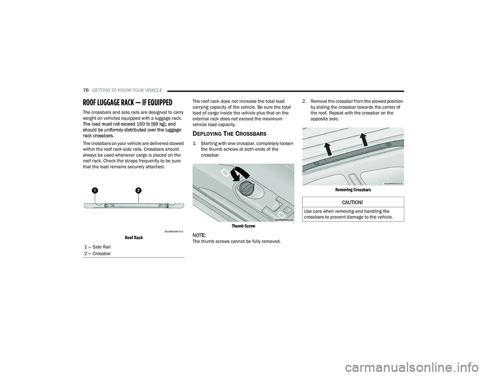
Roof Rack
The roof rack does not increase the total load
carrying capacity of the vehicle. Be sure the total
load of cargo inside the vehicle plus that on the
external rack does not exceed the maximum
vehicle load capacity.
DEPLOYING THE CROSSBARS
1. Starting with one crossbar, completely loosen
the thumb screws at both ends of the
crossbar.
Thumb Screw
NOTE:The thumb screws cannot be fully removed. 2. Remove the crossbar from the stowed position
by sliding the crossbar towards the center of
the roof. Repeat with the crossbar on the
opposite side.
Removing Crossbars
1 — Side Rail
2 — Crossbar
CAUTION!
Use care when removing and handling the
crossbars to prevent damage to the vehicle.
22_WD_OM_EN_USC_t.book Page 76
Page 79 of 332
GETTING TO KNOW YOUR VEHICLE77
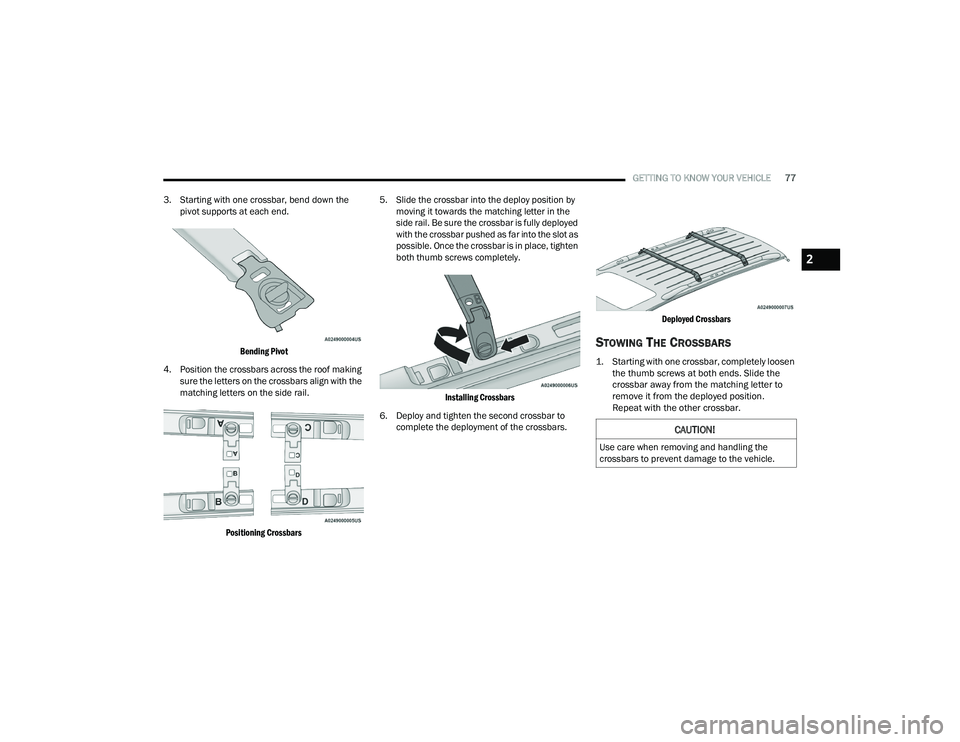
3. Starting with one crossbar, bend down the pivot supports at each end.
Bending Pivot
4. Position the crossbars across the roof making sure the letters on the crossbars align with the
matching letters on the side rail.
Positioning Crossbars
5. Slide the crossbar into the deploy position by
moving it towards the matching letter in the
side rail. Be sure the crossbar is fully deployed
with the crossbar pushed as far into the slot as
possible. Once the crossbar is in place, tighten
both thumb screws completely.
Installing Crossbars
6. Deploy and tighten the second crossbar to complete the deployment of the crossbars.
Deployed Crossbars
STOWING THE CROSSBARS
1. Starting with one crossbar, completely loosen
the thumb screws at both ends. Slide the
crossbar away from the matching letter to
remove it from the deployed position.
Repeat with the other crossbar.
CAUTION!
Use care when removing and handling the
crossbars to prevent damage to the vehicle.
2
22_WD_OM_EN_USC_t.book Page 77
Page 80 of 332
78GETTING TO KNOW YOUR VEHICLE
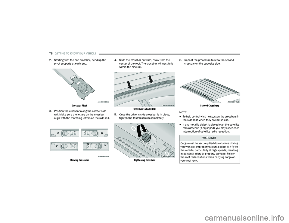
2. Starting with the one crossbar, bend up the pivot supports at each end.
Crossbar Pivot
3. Position the crossbar along the correct side rail. Make sure the letters on the crossbar
align with the matching letters on the side rail.
Stowing Crossbars
4. Slide the crossbar outward, away from the
center of the roof. The crossbar will nest fully
within the side rail.
Crossbar To Side Rail
5. Once the driver’s side crossbar is in place, tighten the thumb screws completely.
Tightening Crossbar
6. Repeat the procedure to stow the second
crossbar on the opposite side.
Stowed Crossbars
NOTE:
To help control wind noise, stow the crossbars in
the side rails when they are not in use.
If any metallic object is placed over the satellite
radio antenna (if equipped), you may experience
interruption of satellite radio reception.
WARNING!
Cargo must be securely tied down before driving
your vehicle. Improperly secured loads can fly off
the vehicle, particularly at high speeds, resulting
in personal injury or property damage. Follow
the roof rack cautions when carrying cargo on
your roof rack.
22_WD_OM_EN_USC_t.book Page 78
Page 83 of 332
GETTING TO KNOW YOUR INSTRUMENT PANEL81
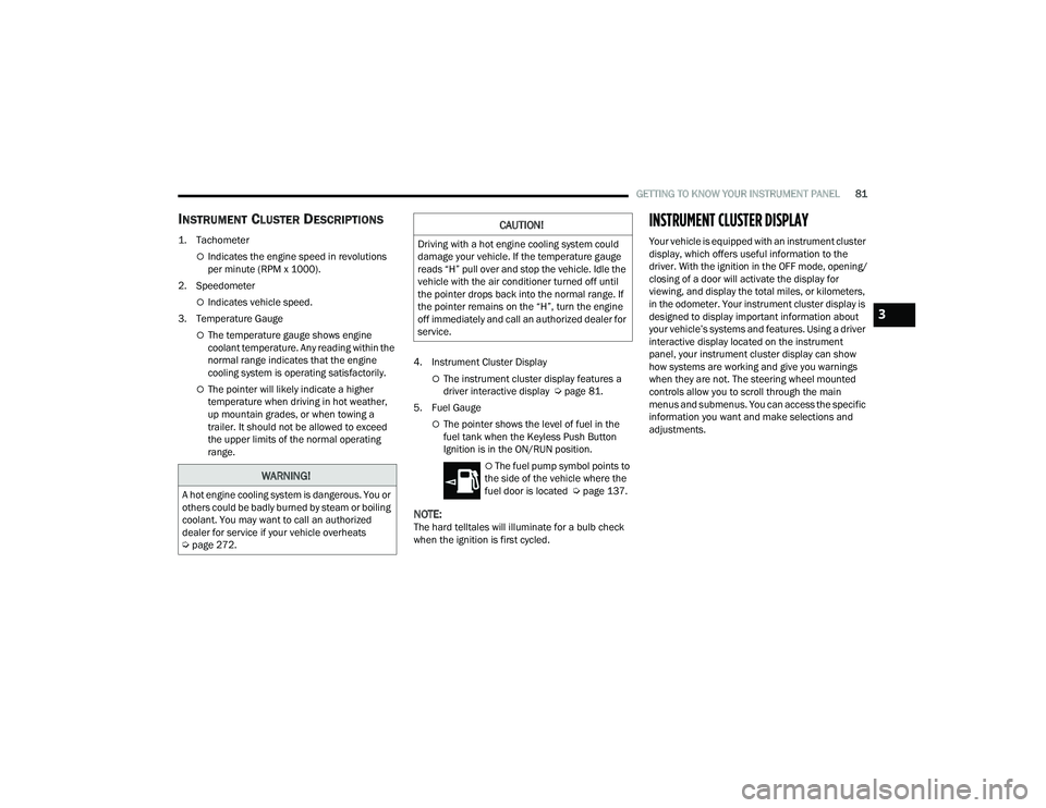
INSTRUMENT CLUSTER DESCRIPTIONS
1. Tachometer
Indicates the engine speed in revolutions
per minute (RPM x 1000).
2. Speedometer
Indicates vehicle speed.
3. Temperature Gauge
The temperature gauge shows engine
coolant temperature. Any reading within the
normal range indicates that the engine
cooling system is operating satisfactorily.
The pointer will likely indicate a higher
temperature when driving in hot weather,
up mountain grades, or when towing a
trailer. It should not be allowed to exceed
the upper limits of the normal operating
range. 4. Instrument Cluster DisplayThe instrument cluster display features a
driver interactive display Ú
page 81.
5. Fuel Gauge
The pointer shows the level of fuel in the
fuel tank when the Keyless Push Button
Ignition is in the ON/RUN position.
The fuel pump symbol points to
the side of the vehicle where the
fuel door is located Ú page 137.
NOTE:The hard telltales will illuminate for a bulb check
when the ignition is first cycled.
INSTRUMENT CLUSTER DISPLAY
Your vehicle is equipped with an instrument cluster
display, which offers useful information to the
driver. With the ignition in the OFF mode, opening/
closing of a door will activate the display for
viewing, and display the total miles, or kilometers,
in the odometer. Your instrument cluster display is
designed to display important information about
your vehicle’s systems and features. Using a driver
interactive display located on the instrument
panel, your instrument cluster display can show
how systems are working and give you warnings
when they are not. The steering wheel mounted
controls allow you to scroll through the main
menus and submenus. You can access the specific
information you want and make selections and
adjustments.
WARNING!
A hot engine cooling system is dangerous. You or
others could be badly burned by steam or boiling
coolant. You may want to call an authorized
dealer for service if your vehicle overheats
Úpage 272.
CAUTION!
Driving with a hot engine cooling system could
damage your vehicle. If the temperature gauge
reads “H” pull over and stop the vehicle. Idle the
vehicle with the air conditioner turned off until
the pointer drops back into the normal range. If
the pointer remains on the “H”, turn the engine
off immediately and call an authorized dealer for
service.
3
22_WD_OM_EN_USC_t.book Page 81
Page 89 of 332
GETTING TO KNOW YOUR INSTRUMENT PANEL87
Trip
Push and release the up or down arrow
button until the Trip icon/title is highlighted in the
instrument cluster display, then push and release
the left or right arrow button to select Trip A
or Trip B.
The Trip A and Trip B information will display the
following:
Distance
Average Fuel Economy
Elapsed Time
Hold the OK button to reset all the information.
Trailer Tow — If Equipped
Push and release the up or down arrow
button until the Trailer Tow Menu icon/title is
highlighted in the instrument cluster display. Push
and release the left or right arrow button to
select Trailer Trip or Trailer Brake.
Trailer Trip will display the following:
Distance
NOTE:Press and hold the OK button to reset all the
information. Trailer Brake will display the following:
Output
Type
Gain
Stop/Start – If Equipped
Push and release the
up or down
arrow button on the steering wheel to
scroll to the Stop/Start menu in the driver
interactive display Ú page 114.
Audio
Push and release the up or down arrow
button until the Audio Menu icon/title is
highlighted in the instrument cluster display. This
menu will display the audio source information,
including the Song name, Artist name, and audio
source with an accompanying graphic.
Messages
Push and release the up or down arrow
button until the Messages Menu item is
highlighted. This feature shows the number of
stored warning messages. Pushing the left or
right arrow button will allow you to see what the
stored messages are.
When no messages are present, main menu icon
will be a closed envelope.
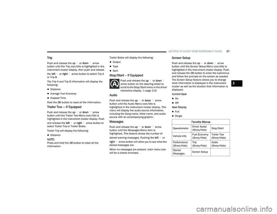
Screen Setup
Push and release the up or down arrow
button until the Screen Setup Menu icon/title is
highlighted in the instrument cluster display. Push
and release the OK button to enter the submenus
and follow the prompts on the screen as needed.
The Screen Setup feature allows you to change
what information is displayed in the instrument
cluster as well as the location that information is
displayed.
Current Gear
On
Off
Gear Display
Full
Single
Favorite Menus
Speedometer Driver Assist
(Show/Hide)Stop/Start
Vehicle Info Fuel Economy
(Show/Hide)Trailer Tow
(Show/Hide)
Performance
(Show/Hide) Trip
(Show/Hide)Audio
(Show/Hide)
Stored
Messages Screen Setup
3
22_WD_OM_EN_USC_t.book Page 87
Page 90 of 332
88GETTING TO KNOW YOUR INSTRUMENT PANEL
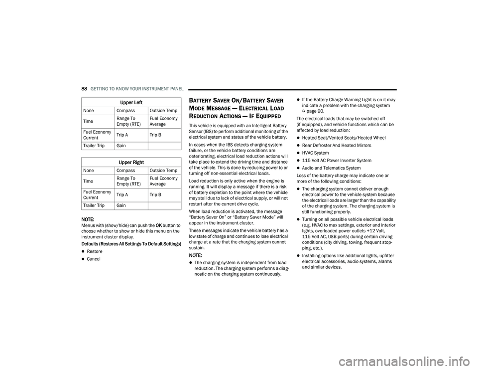
NOTE:Menus with (show/hide) can push the OK button to
choose whether to show or hide this menu on the
instrument cluster display.
Defaults (Restores All Settings To Default Settings)
Restore
Cancel
BATTERY SAVER ON/BATTERY SAVER
M
ODE MESSAGE — ELECTRICAL LOAD
R
EDUCTION ACTIONS — IF EQUIPPED
This vehicle is equipped with an Intelligent Battery
Sensor (IBS) to perform additional monitoring of the
electrical system and status of the vehicle battery.
In cases when the IBS detects charging system
failure, or the vehicle battery conditions are
deteriorating, electrical load reduction actions will
take place to extend the driving time and distance
of the vehicle. This is done by reducing power to or
turning off non-essential electrical loads.
Load reduction is only active when the engine is
running. It will display a message if there is a risk
of battery depletion to the point where the vehicle
may stall due to lack of electrical supply, or will not
restart after the current drive cycle.
When load reduction is activated, the message
“Battery Saver On” or “Battery Saver Mode” will
appear in the instrument cluster.
These messages indicate the vehicle battery has a
low state of charge and continues to lose electrical
charge at a rate that the charging system cannot
sustain.
NOTE:
The charging system is independent from load
reduction. The charging system performs a diag -
nostic on the charging system continuously.
If the Battery Charge Warning Light is on it may
indicate a problem with the charging system
Ú page 90.
The electrical loads that may be switched off
(if equipped), and vehicle functions which can be
affected by load reduction:
Heated Seat/Vented Seats/Heated Wheel
Rear Defroster And Heated Mirrors
HVAC System
115 Volt AC Power Inverter System
Audio and Telematics System
Loss of the battery charge may indicate one or
more of the following conditions:
The charging system cannot deliver enough
electrical power to the vehicle system because
the electrical loads are larger than the capability
of the charging system. The charging system is
still functioning properly.
Turning on all possible vehicle electrical loads
(e.g. HVAC to max settings, exterior and interior
lights, overloaded power outlets +12 Volt,
115 Volt AC, USB ports) during certain driving
conditions (city driving, towing, frequent stop -
ping, etc.).
Installing options like additional lights, upfitter
electrical accessories, audio systems, alarms
and similar devices.
Upper Left
None Compass Outside Temp
Time Range To
Empty (RTE)Fuel Economy
Average
Fuel Economy
Current Trip A Trip B
Trailer Trip Gain
Upper Right
None Compass Outside Temp
Time Range To
Empty (RTE)Fuel Economy
Average
Fuel Economy
Current Trip A Trip B
Trailer Trip Gain
22_WD_OM_EN_USC_t.book Page 88
Page 93 of 332
GETTING TO KNOW YOUR INSTRUMENT PANEL91
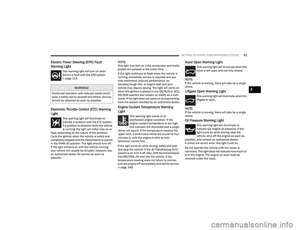
Electric Power Steering (EPS) Fault
Warning Light
This warning light will turn on when
there's a fault with the EPS system
Úpage 114.
Electronic Throttle Control (ETC) Warning
Light
This warning light will illuminate to
indicate a problem with the ETC system.
If a problem is detected while the vehicle
is running, the light will either stay on or
flash depending on the nature of the problem.
Cycle the ignition when the vehicle is safely and
completely stopped and the transmission is placed
in the PARK (P) position. The light should turn off.
If the light remains on with the vehicle running,
your vehicle will usually be drivable; however, see
an authorized dealer for service as soon as
possible.
NOTE:This light may turn on if the accelerator and brake
pedals are pressed at the same time.
If the light continues to flash when the vehicle is
running, immediate service is required and you
may experience reduced performance, an
elevated/rough idle, or engine stall and your
vehicle may require towing. The light will come on
when the ignition is placed in the ON/RUN or ACC/
ON/RUN position and remain on briefly as a bulb
check. If the light does not come on during starting,
have the system checked by an authorized dealer.
Engine Coolant Temperature Warning
Light
This warning light warns of an
overheated engine condition. If the
engine coolant temperature is too high,
this indicator will illuminate and a single
chime will sound. If the temperature reaches the
upper limit, a continuous chime will sound for four
minutes or until the engine is able to cool,
whichever comes first.
If the light turns on while driving, safely pull over
and stop the vehicle. If the Air Conditioning (A/C)
system is on, turn it off. Also, shift the transmission
into NEUTRAL (N) and idle the vehicle. If the
temperature reading does not return to normal,
turn the engine off immediately and call for service
Ú page 249.
Hood Open Warning Light
This warning light will illuminate when the
hood is left open and not fully closed.
NOTE:If the vehicle is moving, there will also be a single
chime.
Liftgate Open Warning Light
This warning light will illuminate when the
liftgate is open.
NOTE:If the vehicle is moving, there will also be a single
chime.
Oil Pressure Warning Light
This warning light will illuminate to
indicate low engine oil pressure. If the
light turns on while driving, stop the
vehicle, shut off the engine as soon as
possible, and contact an authorized dealer.
A chime will sound when this light turns on.
Do not operate the vehicle until the cause is
corrected. This light does not indicate how much oil
is in the engine. The engine oil level must be
checked under the hood.
WARNING!
Continued operation with reduced assist could
pose a safety risk to yourself and others. Service
should be obtained as soon as possible.3
22_WD_OM_EN_USC_t.book Page 91
Page 94 of 332
92GETTING TO KNOW YOUR INSTRUMENT PANEL
Oil Temperature Warning Light
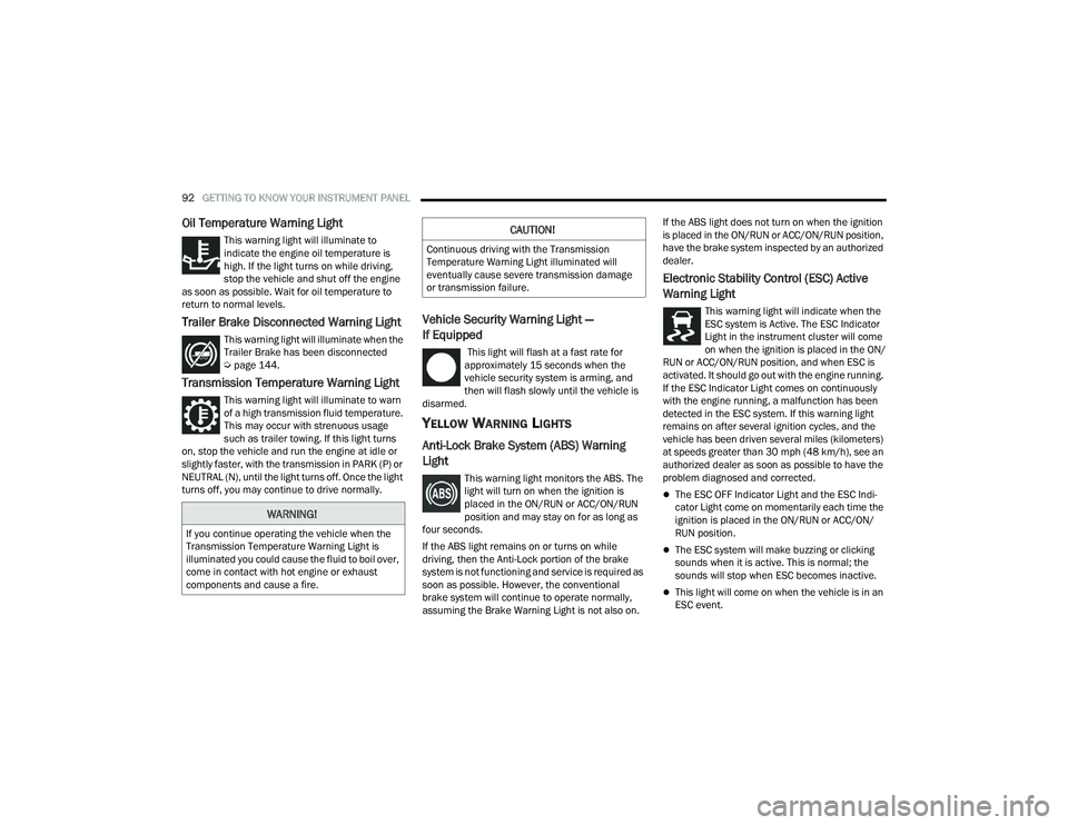
This warning light will illuminate to
indicate the engine oil temperature is
high. If the light turns on while driving,
stop the vehicle and shut off the engine
as soon as possible. Wait for oil temperature to
return to normal levels.
Trailer Brake Disconnected Warning Light
This warning light will illuminate when the
Trailer Brake has been disconnected
Ú page 144.
Transmission Temperature Warning Light
This warning light will illuminate to warn
of a high transmission fluid temperature.
This may occur with strenuous usage
such as trailer towing. If this light turns
on, stop the vehicle and run the engine at idle or
slightly faster, with the transmission in PARK (P) or
NEUTRAL (N), until the light turns off. Once the light
turns off, you may continue to drive normally.
Vehicle Security Warning Light —
If Equipped
This light will flash at a fast rate for
approximately 15 seconds when the
vehicle security system is arming, and
then will flash slowly until the vehicle is
disarmed.
YELLOW WARNING LIGHTS
Anti-Lock Brake System (ABS) Warning
Light
This warning light monitors the ABS. The
light will turn on when the ignition is
placed in the ON/RUN or ACC/ON/RUN
position and may stay on for as long as
four seconds.
If the ABS light remains on or turns on while
driving, then the Anti-Lock portion of the brake
system is not functioning and service is required as
soon as possible. However, the conventional
brake system will continue to operate normally,
assuming the Brake Warning Light is not also on. If the ABS light does not turn on when the ignition
is placed in the ON/RUN or ACC/ON/RUN position,
have the brake system inspected by an authorized
dealer.
Electronic Stability Control (ESC) Active
Warning Light
This warning light will indicate when the
ESC system is Active. The ESC Indicator
Light in the instrument cluster will come
on when the ignition is placed in the ON/
RUN or ACC/ON/RUN position, and when ESC is
activated. It should go out with the engine running.
If the ESC Indicator Light comes on continuously
with the engine running, a malfunction has been
detected in the ESC system. If this warning light
remains on after several ignition cycles, and the
vehicle has been driven several miles (kilometers)
at speeds greater than 30 mph (48 km/h), see an
authorized dealer as soon as possible to have the
problem diagnosed and corrected.
The ESC OFF Indicator Light and the ESC Indi -
cator Light come on momentarily each time the
ignition is placed in the ON/RUN or ACC/ON/
RUN position.
The ESC system will make buzzing or clicking
sounds when it is active. This is normal; the
sounds will stop when ESC becomes inactive.
This light will come on when the vehicle is in an
ESC event.
WARNING!
If you continue operating the vehicle when the
Transmission Temperature Warning Light is
illuminated you could cause the fluid to boil over,
come in contact with hot engine or exhaust
components and cause a fire.
CAUTION!
Continuous driving with the Transmission
Temperature Warning Light illuminated will
eventually cause severe transmission damage
or transmission failure.
22_WD_OM_EN_USC_t.book Page 92