tow DODGE DURANGO 2022 Workshop Manual
[x] Cancel search | Manufacturer: DODGE, Model Year: 2022, Model line: DURANGO, Model: DODGE DURANGO 2022Pages: 332, PDF Size: 19.82 MB
Page 171 of 332
MULTIMEDIA169
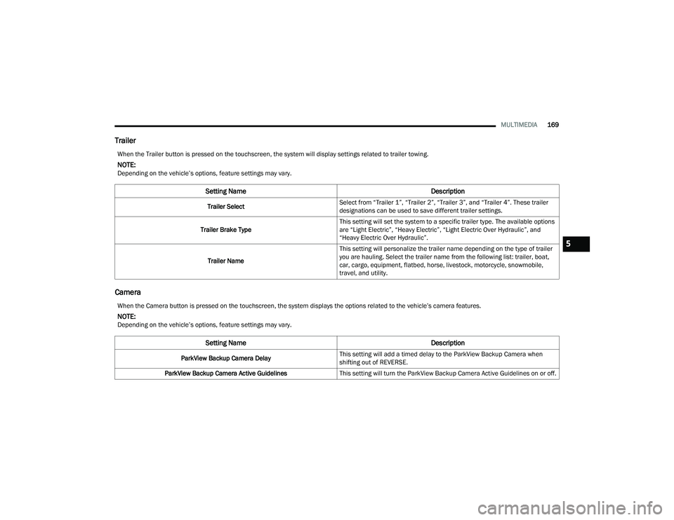
Trailer
Camera
When the Trailer button is pressed on the touchscreen, the system will display settings related to trailer towing.
NOTE:Depending on the vehicle’s options, feature settings may vary.
Setting Name Description
Trailer SelectSelect from “Trailer 1”, “Trailer 2”, “Trailer 3”, and “Trailer 4”. These trailer
designations can be used to save different trailer settings.
Trailer Brake Type This setting will set the system to a specific trailer type. The available options
are “Light Electric”, “Heavy Electric”, “Light Electric Over Hydraulic”, and
“Heavy Electric Over Hydraulic”.
Trailer Name This setting will personalize the trailer name depending on the type of trailer
you are hauling. Select the trailer name from the following list: trailer, boat,
car, cargo, equipment, flatbed, horse, livestock, motorcycle, snowmobile,
travel, and utility.
When the Camera button is pressed on the touchscreen, the system displays the options related to the vehicle’s camera features.
NOTE:Depending on the vehicle’s options, feature settings may vary.
Setting Name
Description
ParkView Backup Camera DelayThis setting will add a timed delay to the ParkView Backup Camera when
shifting out of REVERSE.
ParkView Backup Camera Active Guidelines This setting will turn the ParkView Backup Camera Active Guidelines on or off.
5
22_WD_OM_EN_USC_t.book Page 169
Page 189 of 332
SAFETY187
Disabling And Enabling HSA
This feature can be turned on or turned off.
To change the current setting see Ú page 156.
Towing With HSA
HSA will also provide assistance to mitigate roll
back while towing a trailer.
Rain Brake Support (RBS)
RBS may improve braking performance in wet
conditions. It will periodically apply a small amount
of brake pressure to remove any water buildup on
the front brake rotors. It functions when the
windshield wipers are in LO or HI speed. When Rain
Brake Support is active, there is no notification to
the driver and no driver interaction is required.
Ready Alert Braking (RAB)
RAB may reduce the time required to reach full
braking during emergency braking situations. It
anticipates when an emergency braking situation
may occur by monitoring how fast the throttle is
released by the driver. The Electronic Brake
Controller (EBC) will prepare the brake system for
a panic stop.
Traction Control System (TCS)
The TCS monitors the amount of wheel spin of
each of the driven wheels. If wheel spin is
detected, the TCS may apply brake pressure to the
spinning wheel(s) and/or reduce engine power to
provide enhanced acceleration and stability. A
feature of the TCS, Brake Limited Differential (BLD)
functions similarly to a limited slip differential and
controls the wheel spin across a driven axle. If one
wheel on a driven axle is spinning faster than the other, the system will apply the brake of the
spinning wheel. This will allow more engine power
to be applied to the wheel that is not spinning.
BLD may remain enabled even if TCS and ESC are
in reduced modes.
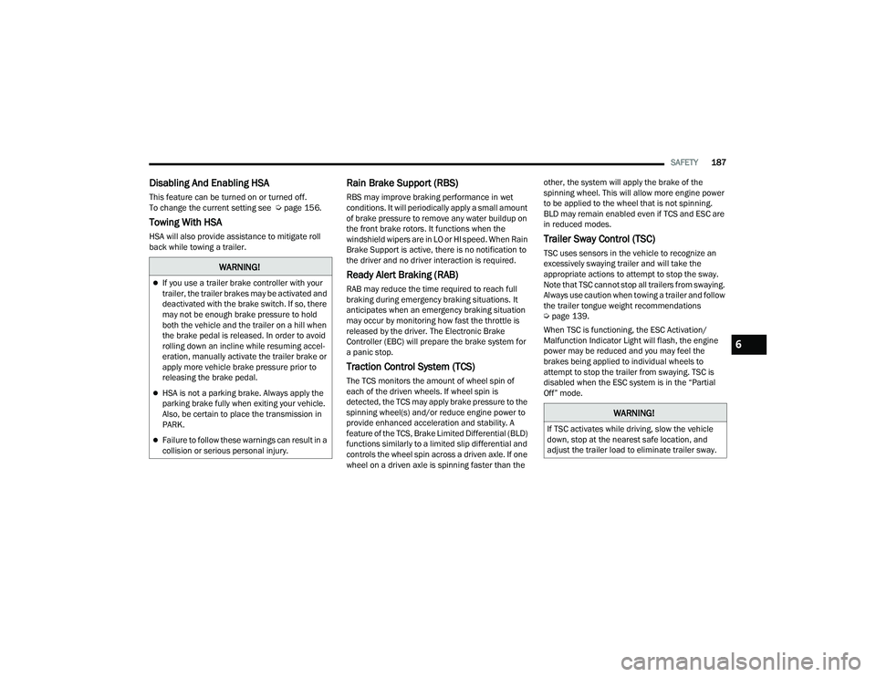
Trailer Sway Control (TSC)
TSC uses sensors in the vehicle to recognize an
excessively swaying trailer and will take the
appropriate actions to attempt to stop the sway.
Note that TSC cannot stop all trailers from swaying.
Always use caution when towing a trailer and follow
the trailer tongue weight recommendations
Ú
page 139.
When TSC is functioning, the ESC Activation/
Malfunction Indicator Light will flash, the engine
power may be reduced and you may feel the
brakes being applied to individual wheels to
attempt to stop the trailer from swaying. TSC is
disabled when the ESC system is in the “Partial
Off” mode.
WARNING!
If you use a trailer brake controller with your
trailer, the trailer brakes may be activated and
deactivated with the brake switch. If so, there
may not be enough brake pressure to hold
both the vehicle and the trailer on a hill when
the brake pedal is released. In order to avoid
rolling down an incline while resuming accel -
eration, manually activate the trailer brake or
apply more vehicle brake pressure prior to
releasing the brake pedal.
HSA is not a parking brake. Always apply the
parking brake fully when exiting your vehicle.
Also, be certain to place the transmission in
PARK.
Failure to follow these warnings can result in a
collision or serious personal injury.
WARNING!
If TSC activates while driving, slow the vehicle
down, stop at the nearest safe location, and
adjust the trailer load to eliminate trailer sway.
6
22_WD_OM_EN_USC_t.book Page 187
Page 190 of 332
188SAFETY
AUXILIARY DRIVING SYSTEMS
BLIND SPOT MONITORING (BSM) —
I
F EQUIPPED
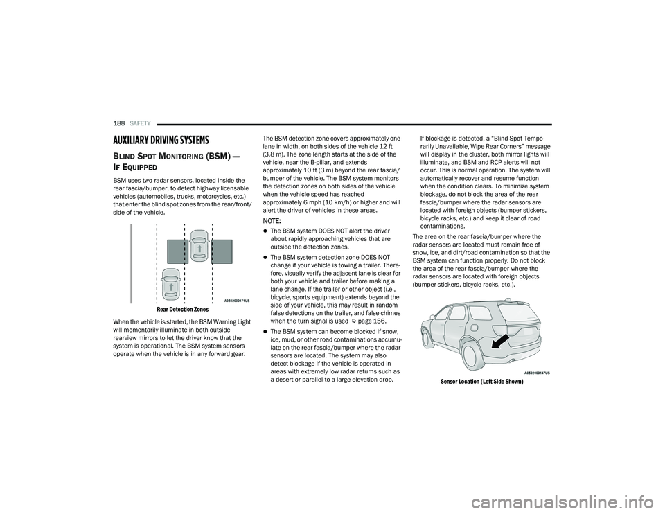
BSM uses two radar sensors, located inside the
rear fascia/bumper, to detect highway licensable
vehicles (automobiles, trucks, motorcycles, etc.)
that enter the blind spot zones from the rear/front/
side of the vehicle.
Rear Detection Zones
When the vehicle is started, the BSM Warning Light
will momentarily illuminate in both outside
rearview mirrors to let the driver know that the
system is operational. The BSM system sensors
operate when the vehicle is in any forward gear. The BSM detection zone covers approximately one
lane in width, on both sides of the vehicle 12 ft
(3.8 m). The zone length starts at the side of the
vehicle, near the B-pillar, and extends
approximately 10 ft (3 m) beyond the rear fascia/
bumper of the vehicle. The BSM system monitors
the detection zones on both sides of the vehicle
when the vehicle speed has reached
approximately 6 mph (10 km/h) or higher and will
alert the driver of vehicles in these areas.
NOTE:
The BSM system DOES NOT alert the driver
about rapidly approaching vehicles that are
outside the detection zones.
The BSM system detection zone DOES NOT
change if your vehicle is towing a trailer. There
-
fore, visually verify the adjacent lane is clear for
both your vehicle and trailer before making a
lane change. If the trailer or other object (i.e.,
bicycle, sports equipment) extends beyond the
side of your vehicle, this may result in random
false detections on the trailer, and false chimes
when the turn signal is used Ú page 156.
The BSM system can become blocked if snow,
ice, mud, or other road contaminations accumu -
late on the rear fascia/bumper where the radar
sensors are located. The system may also
detect blockage if the vehicle is operated in
areas with extremely low radar returns such as
a desert or parallel to a large elevation drop. If blockage is detected, a “Blind Spot Tempo-
rarily Unavailable, Wipe Rear Corners” message
will display in the cluster, both mirror lights will
illuminate, and BSM and RCP alerts will not
occur. This is normal operation. The system will
automatically recover and resume function
when the condition clears. To minimize system
blockage, do not block the area of the rear
fascia/bumper where the radar sensors are
located with foreign objects (bumper stickers,
bicycle racks, etc.) and keep it clear of road
contaminations.
The area on the rear fascia/bumper where the
radar sensors are located must remain free of
snow, ice, and dirt/road contamination so that the
BSM system can function properly. Do not block
the area of the rear fascia/bumper where the
radar sensors are located with foreign objects
(bumper stickers, bicycle racks, etc.).
Sensor Location (Left Side Shown)
22_WD_OM_EN_USC_t.book Page 188
Page 192 of 332
190SAFETY
Overtaking/Passing
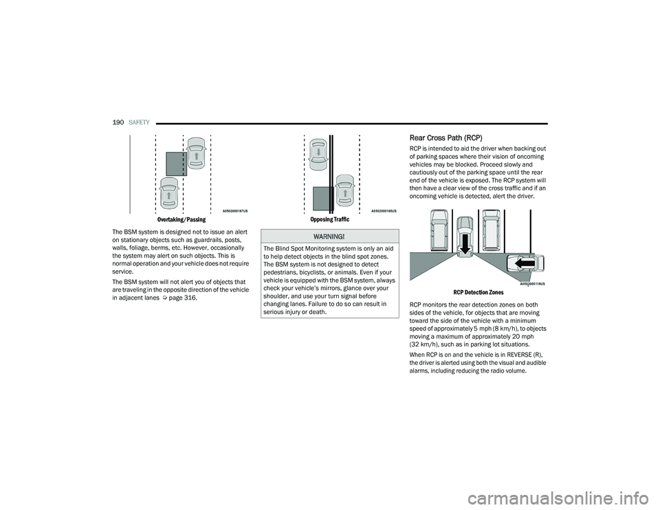
The BSM system is designed not to issue an alert
on stationary objects such as guardrails, posts,
walls, foliage, berms, etc. However, occasionally
the system may alert on such objects. This is
normal operation and your vehicle does not require
service.
The BSM system will not alert you of objects that
are traveling in the opposite direction of the vehicle
in adjacent lanes Ú page 316.
Opposing Traffic
Rear Cross Path (RCP)
RCP is intended to aid the driver when backing out
of parking spaces where their vision of oncoming
vehicles may be blocked. Proceed slowly and
cautiously out of the parking space until the rear
end of the vehicle is exposed. The RCP system will
then have a clear view of the cross traffic and if an
oncoming vehicle is detected, alert the driver.
RCP Detection Zones
RCP monitors the rear detection zones on both
sides of the vehicle, for objects that are moving
toward the side of the vehicle with a minimum
speed of approximately 5 mph (8 km/h), to objects
moving a maximum of approximately 20 mph
(32 km/h), such as in parking lot situations.
When RCP is on and the vehicle is in REVERSE (R),
the driver is alerted using both the visual and audible
alarms, including reducing the radio volume.
WARNING!
The Blind Spot Monitoring system is only an aid
to help detect objects in the blind spot zones.
The BSM system is not designed to detect
pedestrians, bicyclists, or animals. Even if your
vehicle is equipped with the BSM system, always
check your vehicle’s mirrors, glance over your
shoulder, and use your turn signal before
changing lanes. Failure to do so can result in
serious injury or death.
22_WD_OM_EN_USC_t.book Page 190
Page 200 of 332
198SAFETY
(Continued)
Initial Indication
If the driver is unbuckled when the ignition switch
is first in the START or ON/RUN position, a chime
will signal for a few seconds. If the driver or
outboard front seat passenger (if equipped with
outboard front passenger seat BeltAlert) is
unbuckled when the ignition switch is first in the
START or ON/RUN position the Seat Belt Reminder
Light will turn on and remain on until both outboard
front seat belts are buckled. The outboard front
passenger seat BeltAlert is not active when an
outboard front passenger seat is unoccupied.
BeltAlert Warning Sequence
The BeltAlert warning sequence is activated when
the vehicle is moving above a specified vehicle
speed range and the driver or outboard front seat
passenger is unbuckled (if equipped with outboard
front passenger seat BeltAlert) (the outboard front
passenger seat BeltAlert is not active when the
outboard front passenger seat is unoccupied). The
BeltAlert warning sequence starts by blinking the
Seat Belt Reminder Light and sounding an
intermittent chime. Once the BeltAlert warning
sequence has completed, the Seat Belt Reminder
Light will remain on until the seat belts are
buckled. The BeltAlert warning sequence may
repeat based on vehicle speed until the driver and
occupied outboard front seat passenger seat belts
are buckled. The driver should instruct all
occupants to buckle their seat belts.
Change Of Status
If the driver or outboard front seat passenger
(if equipped with outboard front passenger seat
BeltAlert) unbuckles their seat belt while the
vehicle is traveling, the BeltAlert warning sequence
will begin until the seat belts are buckled again.
The outboard front passenger seat BeltAlert is not
active when the outboard front passenger seat is
unoccupied. BeltAlert may be triggered when an
animal or other items are placed on the outboard
front passenger seat or when the seat is folded flat
(if equipped). It is recommended that pets be
restrained in the rear seat (if equipped) in pet
harnesses or pet carriers that are secured by
seat belts, and cargo is properly stowed.
BeltAlert can be activated or deactivated by an
authorized dealer. FCA US LLC does not
recommend deactivating BeltAlert.
NOTE:If BeltAlert has been deactivated and the driver or
outboard front seat passenger (if equipped with
outboard front passenger seat BeltAlert) is
unbuckled the Seat Belt Reminder Light will turn
on and remain on until the driver and outboard
front seat passenger seat belts are buckled.
Lap/Shoulder Belts
All seating positions in your vehicle are equipped
with lap/shoulder belts.
The seat belt webbing retractor will lock only during
very sudden stops or collisions. This feature allows
the shoulder part of the seat belt to move freely
with you under normal conditions. However, in a
collision the seat belt will lock and reduce your risk
of striking the inside of the vehicle or being thrown
out of the vehicle.
WARNING!
Relying on the air bags alone could lead to
more severe injuries in a collision. The air
bags work with your seat belt to restrain you
properly. In some collisions, the air bags won’t
deploy at all. Always wear your seat belt even
though you have air bags.
In a collision, you and your passengers can
suffer much greater injuries if you are not
properly buckled up. You can strike the inte
-
rior of your vehicle or other passengers, or you
can be thrown out of the vehicle. Always be
sure you and others in your vehicle are
buckled up properly.
It is dangerous to ride in a cargo area, inside
or outside of a vehicle. In a collision, people
riding in these areas are more likely to be seri -
ously injured or killed.
Do not allow people to ride in any area of your
vehicle that is not equipped with seats and
seat belts.
22_WD_OM_EN_USC_t.book Page 198
Page 202 of 332
200SAFETY
Lap/Shoulder Belt Operating Instructions
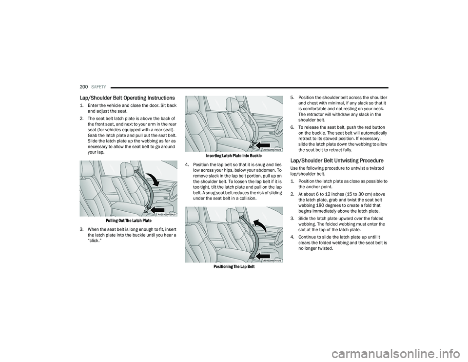
1. Enter the vehicle and close the door. Sit back
and adjust the seat.
2. The seat belt latch plate is above the back of the front seat, and next to your arm in the rear
seat (for vehicles equipped with a rear seat).
Grab the latch plate and pull out the seat belt.
Slide the latch plate up the webbing as far as
necessary to allow the seat belt to go around
your lap.
Pulling Out The Latch Plate
3. When the seat belt is long enough to fit, insert the latch plate into the buckle until you hear a
“click.”
Inserting Latch Plate Into Buckle
4. Position the lap belt so that it is snug and lies low across your hips, below your abdomen. To
remove slack in the lap belt portion, pull up on
the shoulder belt. To loosen the lap belt if it is
too tight, tilt the latch plate and pull on the lap
belt. A snug seat belt reduces the risk of sliding
under the seat belt in a collision.
Positioning The Lap Belt
5. Position the shoulder belt across the shoulder
and chest with minimal, if any slack so that it
is comfortable and not resting on your neck.
The retractor will withdraw any slack in the
shoulder belt.
6. To release the seat belt, push the red button on the buckle. The seat belt will automatically
retract to its stowed position. If necessary,
slide the latch plate down the webbing to allow
the seat belt to retract fully.
Lap/Shoulder Belt Untwisting Procedure
Use the following procedure to untwist a twisted
lap/shoulder belt.
1. Position the latch plate as close as possible to the anchor point.
2. At about 6 to 12 inches (15 to 30 cm) above the latch plate, grab and twist the seat belt
webbing 180 degrees to create a fold that
begins immediately above the latch plate.
3. Slide the latch plate upward over the folded webbing. The folded webbing must enter the
slot at the top of the latch plate.
4. Continue to slide the latch plate up until it clears the folded webbing and the seat belt is
no longer twisted.
22_WD_OM_EN_USC_t.book Page 200
Page 217 of 332
SAFETY215
(Continued)
After an accident, if the vehicle will not start after
performing the reset procedure, the vehicle must
be towed to an authorized dealer to be inspected
and to have the Enhanced Accident Response
System reset.
Maintaining Your Air Bag System
Event Data Recorder (EDR)
This vehicle is equipped with an event data
recorder (EDR). The main purpose of an EDR is to
record, in certain crash or near crash-like
situations, such as an air bag deployment or hitting
a road obstacle, data that will assist in
understanding how a vehicle’s systems performed.
The EDR is designed to record data related to
vehicle dynamics and safety systems for a short
period of time, typically 30 seconds or less. The EDR in this vehicle is designed to record such
data as:
How various systems in your vehicle were oper
-
ating;
Whether or not the driver and passenger safety
belts were buckled/fastened;
How far (if at all) the driver was depressing the
accelerator and/or brake pedal; and,
How fast the vehicle was traveling.
These data can help provide a better
understanding of the circumstances in which
crashes and injuries occur.
NOTE:EDR data are recorded by your vehicle only if a
non-trivial crash situation occurs; no data are
recorded by the EDR under normal driving condi -
tions and no personal data (e.g., name, gender,
age, and crash location) are recorded. However,
other parties, such as law enforcement, could
combine the EDR data with the type of personally
identifying data routinely acquired during a crash
investigation.
WARNING!
Modifications to any part of the air bag system
could cause it to fail when you need it. You
could be injured if the air bag system is not
there to protect you. Do not modify the compo -
nents or wiring, including adding any kind of
badges or stickers to the steering wheel hub
trim cover or the upper passenger side of the
instrument panel. Do not modify the front
fascia/bumper, vehicle body structure, or add
aftermarket side steps or running boards.
It is dangerous to try to repair any part of the
air bag system yourself. Be sure to tell anyone
who works on your vehicle that it has an air
bag system.
Do not attempt to modify any part of your air
bag system. The air bag may inflate acciden -
tally or may not function properly if modifica -
tions are made. Take your vehicle to an
authorized dealer for any air bag system
service. If your seat, including your trim cover
and cushion, needs to be serviced in any way
(including removal or loosening/tightening of
seat attachment bolts), take the vehicle to an
authorized dealer. Only manufacturer
approved seat accessories may be used. If it is
necessary to modify the air bag system for
persons with disabilities, contact an autho -
rized dealer.
WARNING!
6
22_WD_OM_EN_USC_t.book Page 215
Page 228 of 332
226SAFETY
Vehicle With A Center Arm Rest Tether —
Five Or Seven Passenger Seating Only
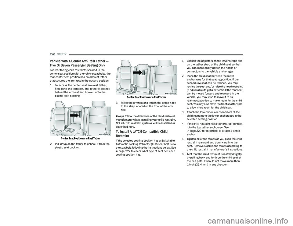
For rear-facing child restraints secured in the
center seat position with the vehicle seat belts, the
rear center seat position has an armrest tether
that secures the arm rest in the upward position.
1. To access the center seat arm rest tether,
first lower the arm rest. The tether is located
behind the armrest and hooked onto the
plastic seat backing.
Center Seat Position Arm Rest Tether
2. Pull down on the tether to unhook it from the plastic seat backing.
Center Seat Position Arm Rest Tether
3. Raise the armrest and attach the tether hook to the strap located on the front of the arm
rest.
Always follow the directions of the child restraint
manufacturer when installing your child restraint.
Not all child restraint systems will be installed as
described here.
To Install A LATCH-Compatible Child
Restraint
If the selected seating position has a Switchable
Automatic Locking Retractor (ALR) seat belt, stow
the seat belt, following the instructions below. See
Ú page 227 to check what type of seat belt each
seating position has.
1. Loosen the adjusters on the lower straps and
on the tether strap of the child seat so that
you can more easily attach the hooks or
connectors to the vehicle anchorages.
2. Place the child seat between the lower anchorages for that seating position. If the
second row seat can be reclined, you may
recline the seat and/or raise the head restraint
(if adjustable) to get a better fit. If the rear seat
can be moved forward and rearward in the
vehicle, you may wish to move it to its
rear-most position to make room for the child
seat. You may also move the front seat forward
to allow more room for the child seat.
3. Attach the lower hooks or connectors of the child restraint to the lower anchorages in the
selected seating position.
4. If the child restraint has a tether strap, connect it to the top tether anchorage. See
Úpage 229 for directions to attach a tether
anchor.
5. Tighten all of the straps as you push the child restraint rearward and downward into the
seat. Remove slack in the straps according to
the child restraint manufacturer’s instructions.
6. Test that the child restraint is installed tightly by pulling back and forth on the child seat at
the belt path. It should not move more than
1 inch (25.4 mm) in any direction.
22_WD_OM_EN_USC_t.book Page 226
Page 229 of 332
SAFETY227
(Continued)
How To Stow An Unused Switchable-ALR
(ALR) Seat Belt:
When using the LATCH attaching system to install
a child restraint, stow all ALR seat belts that are not
being used by other occupants or being used to
secure child restraints. An unused belt could injure
a child if they play with it and accidentally lock the
seat belt retractor. Before installing a child
restraint using the LATCH system, buckle the seat
belt behind the child restraint and out of the child’s
reach. If the buckled seat belt interferes with the
child restraint installation, instead of buckling it
behind the child restraint, route the seat belt
through the child restraint belt path and then
buckle it. Do not lock the seat belt. Remind all
children in the vehicle that the seat belts are not
toys and that they should not play with them.
Installing Child Restraints Using The
Vehicle Seat Belt
Child restraint systems are designed to be secured
in vehicle seats by lap belts or the lap belt portion
of a lap/shoulder belt. The seat belts in the passenger seating positions
are equipped with a Switchable Automatic Locking
Retractor (ALR) that is designed to keep the lap
portion of the seat belt tight around the child
restraint so that it is not necessary to use a locking
clip. The ALR retractor can be “switched” into a
locked mode by pulling all of the webbing out of the
retractor and then letting the webbing retract back
into the retractor. If it is locked, the ALR will make
a clicking noise while the webbing is pulled back
into the retractor Ú
page 202.
Please see the table below and the following
sections for more information.
WARNING!
Improper installation of a child restraint to the
LATCH anchorages can lead to failure of the
restraint. The child could be badly injured or
killed. Follow the child restraint manufac -
turer’s directions exactly when installing an
infant or child restraint.
Child restraint anchorages are designed to
withstand only those loads imposed by
correctly-fitted child restraints. Under no
circumstances are they to be used for adult
seat belts, harnesses, or for attaching other
items or equipment to the vehicle.
WARNING!
Improper installation or failure to properly
secure a child restraint can lead to failure of
the restraint. The child could be badly injured
or killed.
Follow the child restraint manufacturer’s
directions exactly when installing an infant or
child restraint.
WARNING!
6
22_WD_OM_EN_USC_t.book Page 227
Page 235 of 332
SAFETY233
(Continued)
(Continued)
PERIODIC SAFETY CHECKS YOU SHOULD
M
AKE OUTSIDE THE VEHICLE
Tires
Examine tires for excessive tread wear and uneven
wear patterns. Check for stones, nails, glass, or
other objects lodged in the tread or sidewall.
Inspect the tread for cuts and cracks. Inspect
sidewalls for cuts, cracks, and bulges. Check the
lug nut/bolt torque for tightness. Check the tires
(including spare) for proper cold inflation pressure.
WARNING!
An improperly attached, damaged, folded, or
stacked floor mat, or damaged floor mat
fasteners may cause your floor mat to interfere
with the accelerator, brake, or clutch pedals and
cause a loss of vehicle control. To prevent
SERIOUS INJURY or DEATH:
ALWAYS securely attach your
floor mat using the floor mat
fasteners. DO NOT install your
floor mat upside down or turn your
floor mat over. Lightly pull to confirm mat is
secured using the floor mat fasteners on a
regular basis.
ALWAYS REMOVE THE EXISTING
FLOOR MAT FROM THE VEHICLE
before installing any other floor mat.
NEVER install or stack an additional
floor mat on top of an existing floor mat.
ONLY install floor mats designed to fit your
vehicle. NEVER install a floor mat that cannot
be properly attached and secured to your
vehicle. If a floor mat needs to be replaced,
only use a FCA approved floor mat for the
specific make, model, and year of your
vehicle.
ONLY use the driver’s side floor mat on the
driver’s side floor area. To check for interfer -
ence, with the vehicle properly parked with the
engine off, fully depress the accelerator, the
brake, and the clutch pedal (if present) to
check for interference. If your floor mat inter -
feres with the operation of any pedal, or is not
secure to the floor, remove the floor mat from
the vehicle and place the floor mat in your
trunk.
ONLY use the passenger’s side floor mat on
the passenger’s side floor area.
ALWAYS make sure objects cannot fall or slide
into the driver’s side floor area when the
vehicle is moving. Objects can become
trapped under accelerator, brake, or clutch
pedals and could cause a loss of vehicle
control.
NEVER place any objects under the floor mat
(e.g., towels, keys, etc.). These objects could
change the position of the floor mat and may
cause interference with the accelerator,
brake, or clutch pedals.
WARNING!
If the vehicle carpet has been removed and
re-installed, always properly attach carpet to
the floor and check the floor mat fasteners are
secure to the vehicle carpet. Fully depress
each pedal to check for interference with the
accelerator, brake, or clutch pedals then
re-install the floor mats.
It is recommended to only use mild soap and
water to clean your floor mats. After cleaning,
always check your floor mat has been properly
installed and is secured to your vehicle using
the floor mat fasteners by lightly pulling mat.
WARNING!
6
22_WD_OM_EN_USC_t.book Page 233