turn signal DODGE DURANGO 2022 User Guide
[x] Cancel search | Manufacturer: DODGE, Model Year: 2022, Model line: DURANGO, Model: DODGE DURANGO 2022Pages: 332, PDF Size: 19.82 MB
Page 85 of 332
GETTING TO KNOW YOUR INSTRUMENT PANEL83
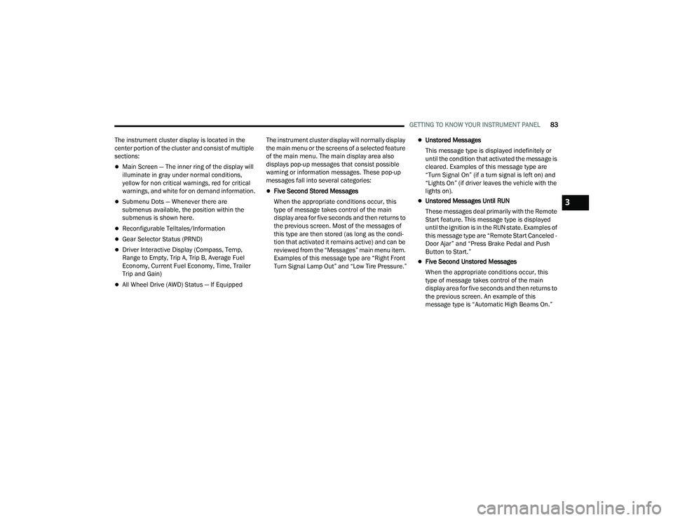
The instrument cluster display is located in the
center portion of the cluster and consist of multiple
sections:
Main Screen — The inner ring of the display will
illuminate in gray under normal conditions,
yellow for non critical warnings, red for critical
warnings, and white for on demand information.
Submenu Dots — Whenever there are
submenus available, the position within the
submenus is shown here.
Reconfigurable Telltales/Information
Gear Selector Status (PRND)
Driver Interactive Display (Compass, Temp,
Range to Empty, Trip A, Trip B, Average Fuel
Economy, Current Fuel Economy, Time, Trailer
Trip and Gain)
All Wheel Drive (AWD) Status — If Equipped The instrument cluster display will normally display
the main menu or the screens of a selected feature
of the main menu. The main display area also
displays pop-up messages that consist possible
warning or information messages. These pop-up
messages fall into several categories:
Five Second Stored Messages
When the appropriate conditions occur, this
type of message takes control of the main
display area for five seconds and then returns to
the previous screen. Most of the messages of
this type are then stored (as long as the condi-
tion that activated it remains active) and can be
reviewed from the “Messages” main menu item.
Examples of this message type are “Right Front
Turn Signal Lamp Out” and “Low Tire Pressure.”
Unstored Messages
This message type is displayed indefinitely or
until the condition that activated the message is
cleared. Examples of this message type are
“Turn Signal On” (if a turn signal is left on) and
“Lights On” (if driver leaves the vehicle with the
lights on).
Unstored Messages Until RUN
These messages deal primarily with the Remote
Start feature. This message type is displayed
until the ignition is in the RUN state. Examples of
this message type are “Remote Start Canceled -
Door Ajar” and “Press Brake Pedal and Push
Button to Start.”
Five Second Unstored Messages
When the appropriate conditions occur, this
type of message takes control of the main
display area for five seconds and then returns to
the previous screen. An example of this
message type is “Automatic High Beams On.”
3
22_WD_OM_EN_USC_t.book Page 83
Page 87 of 332
GETTING TO KNOW YOUR INSTRUMENT PANEL85
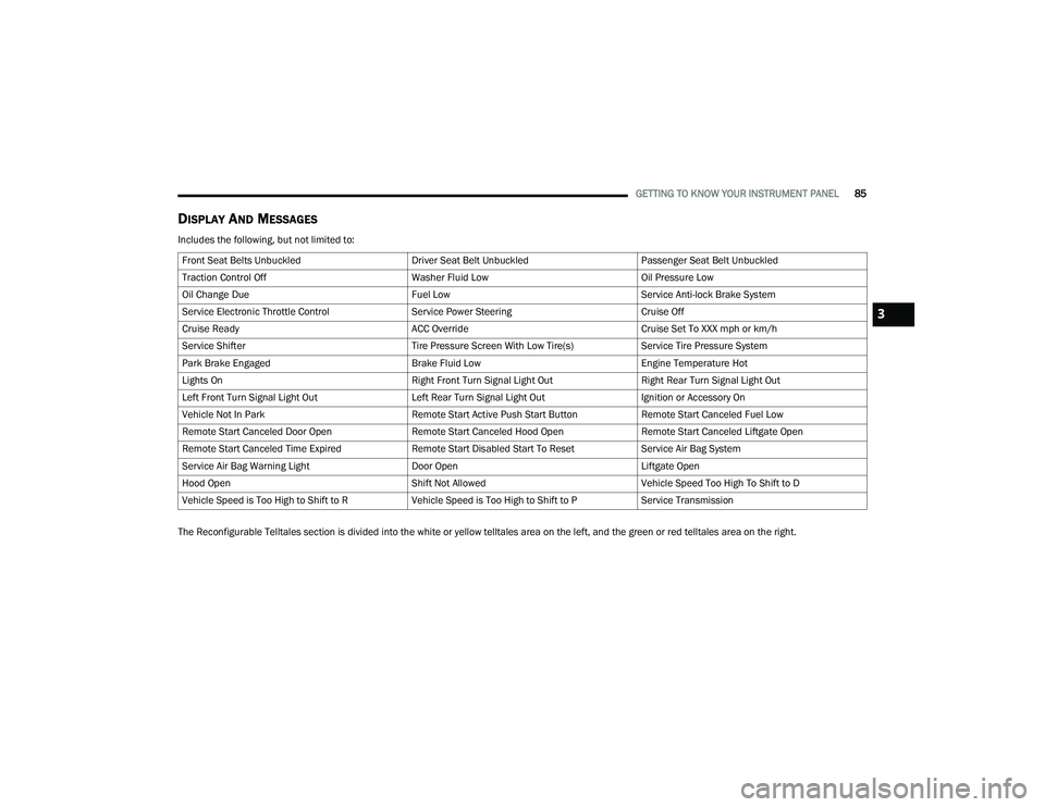
DISPLAY AND MESSAGES
Includes the following, but not limited to:
The Reconfigurable Telltales section is divided into the white or yellow telltales area on the left, and the green or red telltales area on the right.Front Seat Belts Unbuckled
Driver Seat Belt UnbuckledPassenger Seat Belt Unbuckled
Traction Control Off Washer Fluid LowOil Pressure Low
Oil Change Due Fuel LowService Anti-lock Brake System
Service Electronic Throttle Control Service Power SteeringCruise Off
Cruise Ready ACC OverrideCruise Set To XXX mph or km/h
Service Shifter Tire Pressure Screen With Low Tire(s)Service Tire Pressure System
Park Brake Engaged Brake Fluid LowEngine Temperature Hot
Lights On Right Front Turn Signal Light OutRight Rear Turn Signal Light Out
Left Front Turn Signal Light Out Left Rear Turn Signal Light OutIgnition or Accessory On
Vehicle Not In Park Remote Start Active Push Start ButtonRemote Start Canceled Fuel Low
Remote Start Canceled Door Open Remote Start Canceled Hood OpenRemote Start Canceled Liftgate Open
Remote Start Canceled Time Expired Remote Start Disabled Start To ResetService Air Bag System
Service Air Bag Warning Light Door OpenLiftgate Open
Hood Open Shift Not AllowedVehicle Speed Too High To Shift to D
Vehicle Speed is Too High to Shift to R Vehicle Speed is Too High to Shift to PService Transmission
3
22_WD_OM_EN_USC_t.book Page 85
Page 91 of 332
GETTING TO KNOW YOUR INSTRUMENT PANEL89
Unusual driving cycles (short trips separated by
long parking periods).
The vehicle was parked for an extended period
of time (weeks, months).
The battery was recently replaced and was not
charged completely.
The battery was discharged by an electrical load
left on when the vehicle was parked.
The battery was used for an extended period
with the engine not running to supply radio,
lights, chargers, +12 Volt portable appliances
like vacuum cleaners, game consoles and
similar devices.
What to do when an electrical load reduction
action message is present (“Battery Saver On” or
“Battery Saver Mode”)
During a trip:
Reduce power to unnecessary loads if possible:
Turn off redundant lights (interior or exterior)
Check what may be plugged in to power
outlets +12 Volt, 115 Volt AC, USB ports
Check HVAC settings (blower, temperature)
Check the audio settings (volume) After a trip:
Check if any aftermarket equipment was
installed (additional lights, upfitter electrical
accessories, audio systems, alarms) and review
specifications if any (load and Ignition Off Draw
currents).
Evaluate the latest driving cycles (distance,
driving time and parking time).
The vehicle should have service performed if
the message is still present during consecutive
trips, and if the evaluation and driving pattern of
the vehicle did not help to identify the cause.
WARNING LIGHTS AND MESSAGES
The warning/indicator lights will illuminate in the
instrument panel together with a dedicated
message and/or acoustic signal when applicable.
These indications are indicative and precautionary
and as such must not be considered as exhaustive
and/or alternative to the information contained in
the Owner’s Manual, which you are advised to
read carefully in all cases. Always refer to the
information in this chapter in the event of a failure
indication. All active telltales will display first if
applicable. The system check menu may appear
different based upon equipment options and
current vehicle status. Some telltales are optional
and may not appear.
RED WARNING LIGHTS
Seat Belt Reminder Warning Light
This warning light indicates when the
driver or passenger seat belt is
unbuckled. When the ignition is first
placed in the ON/RUN or ACC/ON/RUN
position and if the driver’s seat belt is unbuckled,
a chime will sound and the light will turn on. When
driving, if the driver or front passenger seat belt
remains unbuckled, the Seat Belt Reminder Light
will flash or remain on continuously and a chime
will sound Ú page 196.
Air Bag Warning Light
This warning light will illuminate to
indicate a fault with the air bag, and will
turn on for four to eight seconds as a bulb
check when the ignition is placed in the
ON/RUN or ACC/ON/RUN position. This light will
illuminate with a single chime when a fault with the
air bag has been detected, it will stay on until the
fault is cleared. If the light is either not on during
startup, stays on, or turns on while driving, have
the system inspected at an authorized dealer as
soon as possible.
3
22_WD_OM_EN_USC_t.book Page 89
Page 98 of 332
96GETTING TO KNOW YOUR INSTRUMENT PANEL
Cruise Control Set Indicator Light —
If Equipped
This indicator light will illuminate when
the cruise control is set to the desired
speed Úpage 116.
Front Fog Indicator Light — If Equipped
This indicator light will illuminate when
the front fog lights are on Ú page 47.
LaneSense Indicator Light —
If Equipped
The LaneSense indicator light illuminates
solid green when both lane markings
have been detected and the system is
“armed” and ready to provide visual and
torque warnings if an unintentional lane departure
occurs Ú page 133.
Parking/Headlights On Indicator Light
This indicator light will illuminate when
the parking lights or headlights are
turned on Ú page 47.
Sport Mode Indicator Light
This light will turn on when Sport Mode is
active Úpage 109.
Stop/Start Active Indicator Light —
If Equipped
This indicator light will illuminate when
the Stop/Start function is in “Autostop”
mode Úpage 114.
Turn Signal Indicator Lights
When the left or right turn signal is
activated, the turn signal indicator
will flash independently and the
corresponding exterior turn signal lamps
will flash. Turn signals can be activated when the
multifunction lever is moved down (left) or
up (right).
NOTE:
A continuous chime will sound if the vehicle is
driven more than 1 mile (1.6 km) with either
turn signal on.
Check for an inoperative outside light bulb if
either indicator flashes at a rapid rate.
WHITE INDICATOR LIGHTS
Adaptive Cruise Control (ACC) Ready
Light — If Equipped
This light will turn on when ACC has been
turned on, but is not set Ú page 118.
Cruise Control Ready Indicator Light
This indicator light will illuminate when
the cruise control is ready, but not set
Úpage 116.
LaneSense Indicator Light — If Equipped
When the LaneSense system is ON, but
not armed, the LaneSense indicator light
illuminates solid white. This occurs when
only left, right, or neither lane line has
been detected. If a single lane line is detected, the
system is ready to provide only visual warnings if
an unintentional lane departure occurs on the
detected lane line Ú page 133.
BLUE INDICATOR LIGHTS
High Beam Indicator Light
This indicator light will illuminate to
indicate that the high beam headlights
are on. With the low beams activated,
push the multifunction lever forward
(toward the front of the vehicle) to turn on the high
beams. Pull the multifunction lever rearward
(toward the rear of the vehicle) to turn off the high
beams. If the high beams are off, pull the lever
toward you for a temporary high beam on, “flash to
pass” scenario.
22_WD_OM_EN_USC_t.book Page 96
Page 125 of 332
STARTING AND OPERATING123
If there is no vehicle ahead, the vehicle will
maintain the set speed. If a slower moving vehicle
is detected in the same lane, the instrument
cluster display will show the ACC Set With Target
Detected Indicator Light. The system will then
adjust the vehicle speed automatically to maintain
the distance setting, regardless of the set speed.
The vehicle will then maintain the set distance
until:
The vehicle ahead accelerates to a speed above
the set speed.
The vehicle ahead moves out of your lane or
view of the sensor.
The distance setting is changed.
The system disengages Ú page 120.
The maximum braking applied by ACC is limited;
however, the driver can always apply the brakes
manually, if necessary.
NOTE:The brake lights will illuminate whenever the ACC
system applies the brakes.
A Proximity Warning will alert the driver if ACC
predicts that its maximum braking level is not
sufficient to maintain the set distance. If this
occurs, a visual alert “BRAKE!” will flash in the
instrument cluster display and a chime will sound
while ACC continues to apply its maximum braking
capacity.
NOTE:The “BRAKE!” screen in the instrument cluster
display is a warning for the driver to take action
and does not necessarily mean that the Forward
Collision Warning system is applying the brakes
autonomously.
Overtake Aid
When driving with Adaptive Cruise Control (ACC)
engaged and following a vehicle, the system will
provide an additional acceleration up to the ACC
set speed to assist in passing the vehicle. This
additional acceleration is triggered when the driver
utilizes the left turn signal and will only be active
when passing on the left hand side.
ACC Operation At Stop
If the ACC system brings your vehicle to a standstill
while following a vehicle ahead, your vehicle will
resume motion, without any driver interaction, if
the vehicle ahead starts moving within two
seconds of your vehicle coming to a standstill.
If the target vehicle does not start moving within
two seconds of your vehicle coming to a standstill,
the ACC with Stop system will cancel and the
brakes will release. A cancel message will display
on the instrument cluster display and produce a
warning chime. Driver intervention will be required
at this moment. While ACC with Stop is holding your vehicle at a
standstill, if the driver seat belt is unbuckled or the
driver door is opened, the ACC with Stop system
will cancel and the brakes will release. A cancel
message will display on the instrument cluster
display and produce a warning chime. The driver
must now manually operate the vehicle’s
accelerator and brakes.Display Warnings And Maintenance
“WIPE FRONT RADAR SENSOR IN FRONT OF
VEHICLE” WARNING
The “ACC/FCW Unavailable Wipe Front Radar
Sensor” warning will display and a chime will
sound when conditions temporarily limit system
performance.
This most often occurs at times of poor visibility,
such as in snow or heavy rain. The ACC system may
also become temporarily blinded due to
obstructions, such as mud, dirt or ice.
WARNING!
When the ACC system is resumed, the driver
must ensure that there are no pedestrians,
vehicles or objects in the path of the vehicle.
Failure to follow these warnings can result in a
collision and death or serious personal injury.4
22_WD_OM_EN_USC_t.book Page 123
Page 136 of 332
134STARTING AND OPERATING
When both lane markings are detected and the
driver drifts out of the lane (no turn signal applied),
the LaneSense system provides a haptic warning
in the form of torque applied to the steering wheel
to prompt the driver to remain within the lane
boundaries. If the driver continues to drift out of
the lane, the LaneSense system provides a visual
warning through the instrument cluster display to
prompt the driver to remain within the lane
boundaries.
The driver may manually override the haptic
warning by applying force to the steering wheel at
any time.
When only a single lane marking is detected and
the driver drifts across the lane marking (no turn
signal applied), the LaneSense system provides
visual warnings through the instrument cluster
display to prompt the driver to remain within the
lane. When only a single lane marking is detected,
a haptic or a torque warning will not be provided.
NOTE:When operating conditions have been met, the
LaneSense system will monitor if the driver’s
hands are on the steering wheel and provide an
audible warning to the driver if removed. The
system will cancel if the driver does not return their
hands to the wheel.
TURNING LANESENSE ON OR OFF
The LaneSense button is located on the
switch panel below the Uconnect display.
To turn the LaneSense system on, push the
LaneSense button (LED turns off). A “LaneSense
On” message is shown in the instrument cluster
display.
To turn the LaneSense system off, push the
LaneSense button once (LED turns on).
NOTE:The LaneSense system will retain the last system
state on or off from the last ignition cycle when the
ignition is placed in the ON/RUN position.
LANESENSE WARNING MESSAGE
The LaneSense system will indicate the current
lane drift condition through the instrument cluster
display.
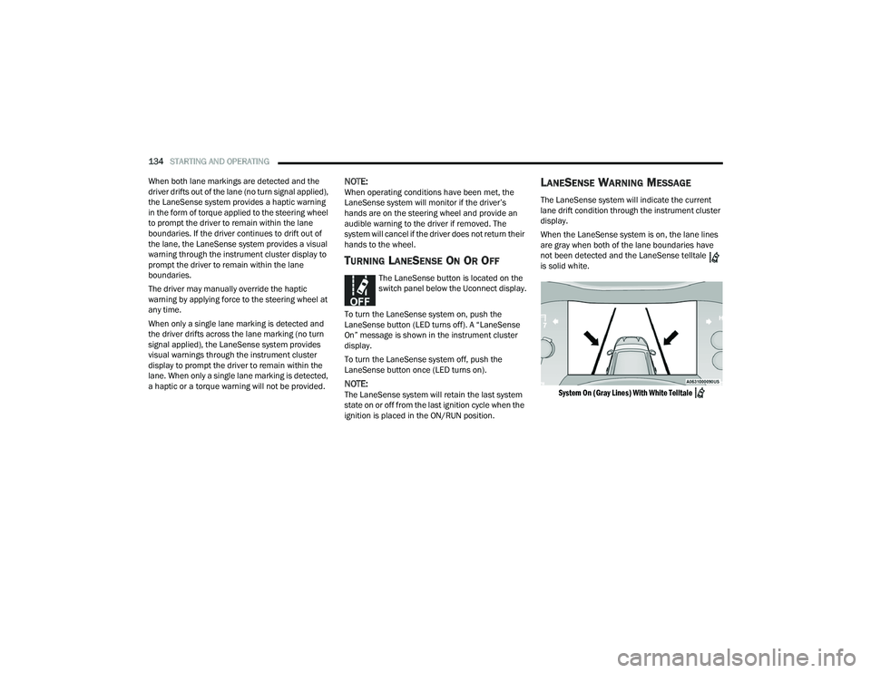
When the LaneSense system is on, the lane lines
are gray when both of the lane boundaries have
not been detected and the LaneSense telltale
is solid white.
System On (Gray Lines) With White Telltale
22_WD_OM_EN_USC_t.book Page 134
Page 138 of 332
136STARTING AND OPERATING
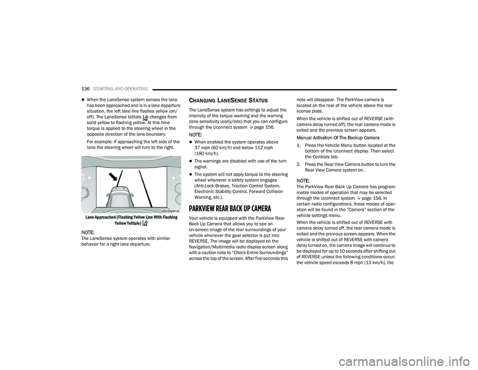
When the LaneSense system senses the lane
has been approached and is in a lane departure
situation, the left lane line flashes yellow (on/
off). The LaneSense telltale changes from
solid yellow to flashing yellow. At this time
torque is applied to the steering wheel in the
opposite direction of the lane boundary.
For example: If approaching the left side of the
lane the steering wheel will turn to the right.
Lane Approached (Flashing Yellow Line With Flashing Yellow Telltale)
NOTE:The LaneSense system operates with similar
behavior for a right lane departure.
CHANGING LANESENSE STATUS
The LaneSense system has settings to adjust the
intensity of the torque warning and the warning
zone sensitivity (early/late) that you can configure
through the Uconnect system Ú page 156.
NOTE:
When enabled the system operates above
37 mph (60 km/h) and below 112 mph
(180 km/h).
The warnings are disabled with use of the turn
signal.
The system will not apply torque to the steering
wheel whenever a safety system engages
(Anti-Lock Brakes, Traction Control System,
Electronic Stability Control, Forward Collision
Warning, etc.).
PARKVIEW REAR BACK UP CAMERA
Your vehicle is equipped with the ParkView Rear
Back Up Camera that allows you to see an
on-screen image of the rear surroundings of your
vehicle whenever the gear selector is put into
REVERSE. The image will be displayed on the
Navigation/Multimedia radio display screen along
with a caution note to “Check Entire Surroundings”
across the top of the screen. After five seconds this note will disappear. The ParkView camera is
located on the rear of the vehicle above the rear
license plate.
When the vehicle is shifted out of REVERSE (with
camera delay turned off), the rear camera mode is
exited and the previous screen appears.
Manual Activation Of The Backup Camera
1. Press the Vehicle Menu button located at the
bottom of the Uconnect display. Then select
the Controls tab.
2. Press the Rear View Camera button to turn the Rear View Camera system on.
NOTE:The ParkView Rear Back Up Camera has program -
mable modes of operation that may be selected
through the Uconnect system Ú page 156. In
certain radio configurations, these modes of oper -
ation will be found in the “Camera” section of the
vehicle settings menu.
When the vehicle is shifted out of REVERSE with
camera delay turned off, the rear camera mode is
exited and the previous screen appears. When the
vehicle is shifted out of REVERSE with camera
delay turned on, the camera image will continue to
be displayed for up to 10 seconds after shifting out
of REVERSE unless the following conditions occur:
the vehicle speed exceeds 8 mph (13 km/h), the
22_WD_OM_EN_USC_t.book Page 136
Page 149 of 332
STARTING AND OPERATING147
Display Messages
The trailer brake control interacts with the
instrument cluster display. Display messages,
along with a single chime, will be displayed when a
malfunction is determined in the trailer
connection, trailer brake control, or on the trailer
Ú page 81.
NOTE:
An aftermarket controller may be available for
use with trailers with air or EOH trailer brake
systems. To determine the type of brakes on
your trailer and the availability of controllers,
check with your trailer manufacturer or dealer.
Removal of the ITBM will cause errors and it
may cause damage to the electrical system and
electronic modules of the vehicle. See an autho -
rized dealer if an aftermarket module is to be
installed.
Towing Requirements — Trailer Lights And
Wiring
Whenever pulling a trailer, regardless of the trailer
size, stoplights and turn signals on the trailer are
required for motoring safety.
The Trailer Tow Package may include a four- and
seven-pin wiring harness. Use a factory approved
trailer harness and connector.
NOTE:Do not cut or splice wiring into the vehicle’s wiring
harness.
The electrical connections are all complete to the
vehicle but you must mate the harness to a trailer
connector. Refer to the following illustrations.
NOTE:
Disconnect the trailer wiring connector from the
vehicle (or any other device plugged into
vehicle’s electrical connectors) before
launching a boat into water.
Be sure to reconnect once clear from water
area.
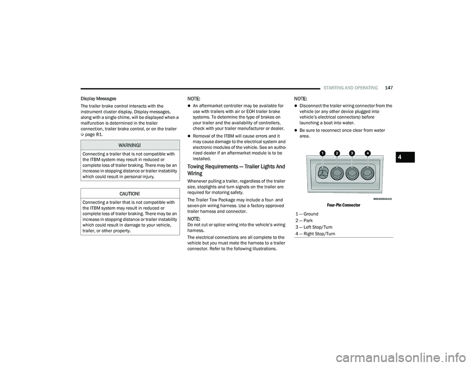
Four-Pin Connector
WARNING!
Connecting a trailer that is not compatible with
the ITBM system may result in reduced or
complete loss of trailer braking. There may be an
increase in stopping distance or trailer instability
which could result in personal injury.
CAUTION!
Connecting a trailer that is not compatible with
the ITBM system may result in reduced or
complete loss of trailer braking. There may be an
increase in stopping distance or trailer instability
which could result in damage to your vehicle,
trailer, or other property.
1 — Ground
2 — Park
3 — Left Stop/Turn
4 — Right Stop/Turn
4
22_WD_OM_EN_USC_t.book Page 147
Page 165 of 332
MULTIMEDIA163
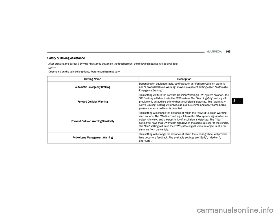
Safety & Driving Assistance
After pressing the Safety & Driving Assistance button on the touchscreen, the following settings will be available:
NOTE:Depending on the vehicle’s options, feature settings may vary.
Setting Name Description
Automatic Emergency BrakingDepending on equipped radio, settings such as “Forward Collision Warning”
and “Forward Collision Warning” maybe in a parent setting called “Automatic
Emergency Braking”.
Forward Collision Warning This setting will turn the Forward Collision Warning (FCW) system on or off. The
“Off” setting will deactivate the FCW system. The “Warning Only” setting will
provide only an audible chime when a collision is detected. The “Warning +
Active Braking” setting will provide an audible chime and apply some brake
pressure when a collision is detected.
Forward Collision Warning Sensitivity This setting will change the distance at which the Forward Collision Warning
alert sounds. The “Medium” setting will have the FCW system signal when an
object is in view, and the possibility of a collision is detected. The “Near”
setting will have the FCW system signal when the object is closer to the vehicle.
The “Far” setting will have the FCW system signal when an object is at a far
distance from the vehicle.
Active Lane Management Warning This setting will change the distance at which the steering wheel will provide
lane departure feedback. The available settings are “Early”, “Medium”,
and “Late”.
5
22_WD_OM_EN_USC_t.book Page 163
Page 190 of 332
188SAFETY
AUXILIARY DRIVING SYSTEMS
BLIND SPOT MONITORING (BSM) —
I
F EQUIPPED
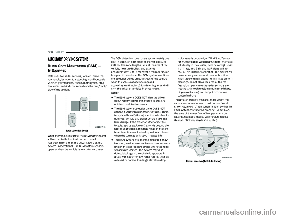
BSM uses two radar sensors, located inside the
rear fascia/bumper, to detect highway licensable
vehicles (automobiles, trucks, motorcycles, etc.)
that enter the blind spot zones from the rear/front/
side of the vehicle.
Rear Detection Zones
When the vehicle is started, the BSM Warning Light
will momentarily illuminate in both outside
rearview mirrors to let the driver know that the
system is operational. The BSM system sensors
operate when the vehicle is in any forward gear. The BSM detection zone covers approximately one
lane in width, on both sides of the vehicle 12 ft
(3.8 m). The zone length starts at the side of the
vehicle, near the B-pillar, and extends
approximately 10 ft (3 m) beyond the rear fascia/
bumper of the vehicle. The BSM system monitors
the detection zones on both sides of the vehicle
when the vehicle speed has reached
approximately 6 mph (10 km/h) or higher and will
alert the driver of vehicles in these areas.
NOTE:
The BSM system DOES NOT alert the driver
about rapidly approaching vehicles that are
outside the detection zones.
The BSM system detection zone DOES NOT
change if your vehicle is towing a trailer. There
-
fore, visually verify the adjacent lane is clear for
both your vehicle and trailer before making a
lane change. If the trailer or other object (i.e.,
bicycle, sports equipment) extends beyond the
side of your vehicle, this may result in random
false detections on the trailer, and false chimes
when the turn signal is used Ú page 156.
The BSM system can become blocked if snow,
ice, mud, or other road contaminations accumu -
late on the rear fascia/bumper where the radar
sensors are located. The system may also
detect blockage if the vehicle is operated in
areas with extremely low radar returns such as
a desert or parallel to a large elevation drop. If blockage is detected, a “Blind Spot Tempo-
rarily Unavailable, Wipe Rear Corners” message
will display in the cluster, both mirror lights will
illuminate, and BSM and RCP alerts will not
occur. This is normal operation. The system will
automatically recover and resume function
when the condition clears. To minimize system
blockage, do not block the area of the rear
fascia/bumper where the radar sensors are
located with foreign objects (bumper stickers,
bicycle racks, etc.) and keep it clear of road
contaminations.
The area on the rear fascia/bumper where the
radar sensors are located must remain free of
snow, ice, and dirt/road contamination so that the
BSM system can function properly. Do not block
the area of the rear fascia/bumper where the
radar sensors are located with foreign objects
(bumper stickers, bicycle racks, etc.).
Sensor Location (Left Side Shown)
22_WD_OM_EN_USC_t.book Page 188