run DODGE DURANGO 2022 Owner's Manual
[x] Cancel search | Manufacturer: DODGE, Model Year: 2022, Model line: DURANGO, Model: DODGE DURANGO 2022Pages: 332, PDF Size: 19.82 MB
Page 50 of 332
48GETTING TO KNOW YOUR VEHICLE
To turn off the headlights, rotate the headlight
switch back to the O (off) position.
NOTE:For vehicles sold in Canada, rotate the headlight
switch clockwise from the parking lights and
instrument panel lights position to the first detent
to turn on headlights, parking lights, and
instrument panel lights. Rotate the headlight
switch to the second detent for the AUTO position.
NOTE:
Your vehicle is equipped with plastic headlight
and fog light (if equipped) lenses that are lighter
and less susceptible to stone breakage than
glass lights. Plastic is not as scratch resistant as
glass and therefore different lens cleaning
procedures must be followed.
To minimize the possibility of scratching the
lenses and reducing light output, avoid wiping
with a dry cloth. To remove road dirt, wash with
a mild soap solution followed by rinsing.
DAYTIME RUNNING LIGHTS (DRLS)
The Daytime Running Lights (DRLs) come on
whenever the engine is running. The lights will
remain on until the ignition is placed in the OFF
position, or the parking brake is engaged. The
headlight switch must be used during normal
nighttime driving.
NOTE:
For vehicles sold in Canada, the Daytime
Running Lights will automatically deactivate
when the front fog lights are turned on.
If allowed by law in the country in which the
vehicle was purchased, the Daytime Running
Lights can be turned on and off using the
Uconnect system Ú page 156.
On some vehicles, the Daytime Running Lights
may deactivate or reduce intensity on one side
of the vehicle (when a turn signal is activated on
that side), or on both sides of the vehicle (when
the hazard warning lights are activated).
HIGH/LOW BEAM SWITCH
Push the multifunction lever toward the instrument
panel to switch the headlights to high beams. Pulling
the multifunction back will turn the low beams on.
AUTOMATIC HIGH BEAM — IF EQUIPPED
The Automatic High Beam Headlamp Control
system provides increased forward lighting at night
by automatically controlling the high beams
through the use of a camera mounted on the
inside rearview mirror. This camera detects vehicle
specific light and automatically switches from high
beams to low beams until the approaching vehicle
is out of view.
NOTE:
The Automatic High Beam Headlamp Control can
be turned on or off by selecting or deselecting
“Auto Dim High Beams” within your Uconnect
Settings
Ú
page 156, as well as turning the
headlight switch to the AUTO position.
Broken, muddy, or obstructed headlights and
taillights of vehicles in the field of view will
cause headlights to remain on longer (closer to
the vehicle). Also, dirt, film, and other obstruc -
tions on the windshield or camera lens will
cause the system to function improperly.
If the windshield or Automatic High Beam Head -
lamp Control mirror is replaced, the mirror must
be re-aimed to ensure proper performance.
See a local authorized dealer.CAUTION!
Do not use abrasive cleaning components,
solvents, steel wool or other abrasive materials
to clean the lenses.
22_WD_OM_EN_USC_t.book Page 48
Page 51 of 332
GETTING TO KNOW YOUR VEHICLE49
To opt out of the Advanced Auto High-Beam
Sensitivity Control (default) and enter Reduced
High-Beam Sensitivity Control (not recom -
mended), toggle high beam lever six full on/off
cycles within 10 seconds of ignition ON. System
will return to default setting upon ignition off.
FLASH-TO-PASS
You can signal another vehicle with your headlights
by lightly pulling the multifunction lever toward you.
This will cause the high beam headlights to turn on,
and remain on, until the lever is released.
AUTOMATIC HEADLIGHTS
This system automatically turns the headlights on
or off according to ambient light levels. To turn the
system on, rotate the headlight switch
counterclockwise to the AUTO position. When the
system is on, the headlight time delay feature is
also on. This means the headlights will stay on for
up to 90 seconds after you place the ignition into
the OFF position. The headlight time delay can be
programmed 0/30/60/90 seconds within
Uconnect Settings Ú page 156.
To turn the automatic system off, move the
headlight switch out of the AUTO position.
NOTE:The engine must be running before the headlights
will come on in the automatic mode.
PARKING LIGHTS AND PANEL LIGHTS
To turn on the parking lights and instrument panel
lights, rotate the headlight switch clockwise. To
turn off the parking lights, rotate the headlight
switch back to the O (off) position.
NOTE:Vehicles sold in Canada are equipped with a head -
light switch with an AUTO and ON detent but
without an OFF detent. Headlights will be deacti -
vated when the headlight switch is placed in the
parking lights position. However, the Daytime
Running Lights (DRLs) will be activated along with
the front and rear marker lights. The DRLs may be
deactivated when the parking brake is engaged.
AUTOMATIC HEADLIGHTS WITH WIPERS
If your vehicle is equipped with Automatic
Headlights, it also has this
customer-programmable feature. When your
headlights are in the automatic mode and the
engine is running, they will automatically turn on
when the wiper system is on. This feature is
programmable through the Uconnect system
Ú page 156.
NOTE:When your headlights come on during the daytime,
the vehicle will monitor outside brightness and
decide if the instrument panel needs to be dimmed
or not Ú page 51.
HEADLIGHT DELAY
To assist when exiting the vehicle, the headlight
delay feature will leave the headlights on for up to
90 seconds. This delay is initiated when the
ignition is placed in the OFF position while the
headlight switch is on, and then the headlight
switch is cycled off. Headlight delay can be
canceled by either turning the headlight switch on
then off, or by placing the ignition in the ON
position.
NOTE:The headlight delay time is programmable through
the Uconnect system Ú page 156.
LIGHTS-ON REMINDER
If the headlights, parking lights, or cargo lights are
left on after the ignition is placed in the OFF
position, the vehicle will chime when the driver’s
door is opened.
FOG LIGHTS — IF EQUIPPED
The fog lights are turned on by pushing fog light
button on the headlight switch.
2
22_WD_OM_EN_USC_t.book Page 49
Page 54 of 332
52GETTING TO KNOW YOUR VEHICLE
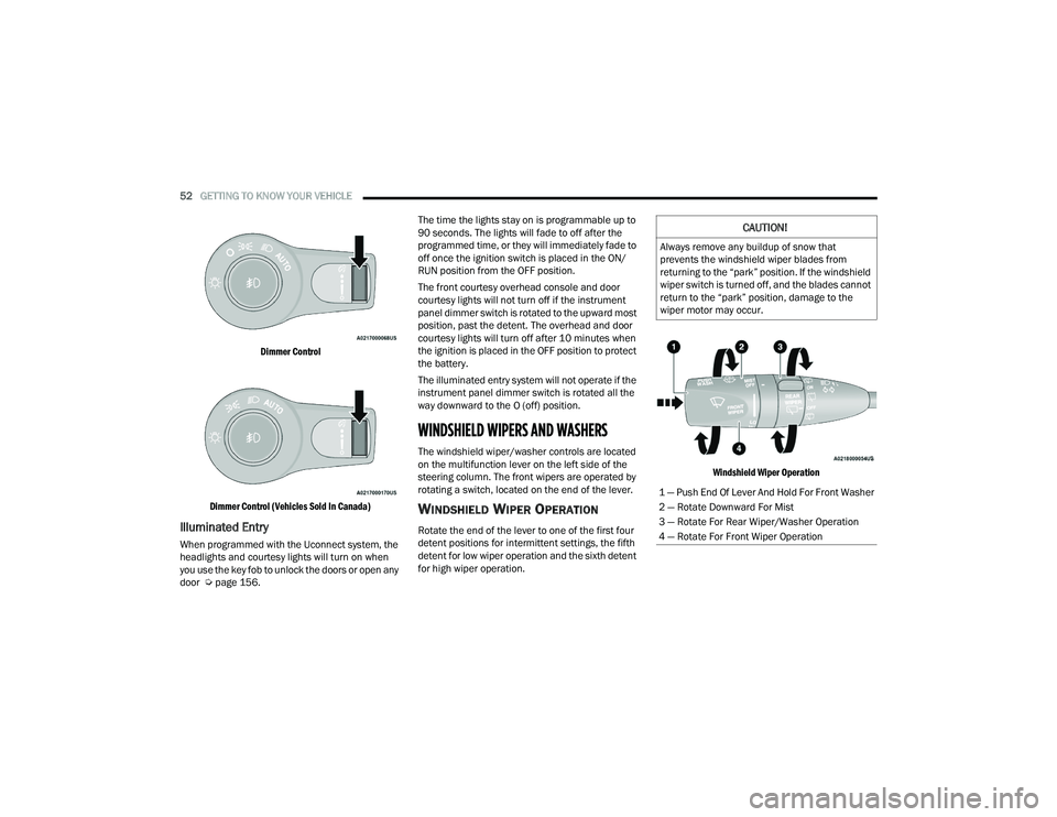
Dimmer Control
Dimmer Control (Vehicles Sold In Canada)
Illuminated Entry
When programmed with the Uconnect system, the
headlights and courtesy lights will turn on when
you use the key fob to unlock the doors or open any
door Ú page 156. The time the lights stay on is programmable up to
90 seconds. The lights will fade to off after the
programmed time, or they will immediately fade to
off once the ignition switch is placed in the ON/
RUN position from the OFF position.
The front courtesy overhead console and door
courtesy lights will not turn off if the instrument
panel dimmer switch is rotated to the upward most
position, past the detent. The overhead and door
courtesy lights will turn off after 10 minutes when
the ignition is placed in the OFF position to protect
the battery.
The illuminated entry system will not operate if the
instrument panel dimmer switch is rotated all the
way downward to the O (off) position.
WINDSHIELD WIPERS AND WASHERS
The windshield wiper/washer controls are located
on the multifunction lever on the left side of the
steering column. The front wipers are operated by
rotating a switch, located on the end of the lever.
WINDSHIELD WIPER OPERATION
Rotate the end of the lever to one of the first four
detent positions for intermittent settings, the fifth
detent for low wiper operation and the sixth detent
for high wiper operation.
Windshield Wiper Operation
CAUTION!
Always remove any buildup of snow that
prevents the windshield wiper blades from
returning to the “park” position. If the windshield
wiper switch is turned off, and the blades cannot
return to the “park” position, damage to the
wiper motor may occur.
1 — Push End Of Lever And Hold For Front Washer
2 — Rotate Downward For Mist
3 — Rotate For Rear Wiper/Washer Operation
4 — Rotate For Front Wiper Operation
22_WD_OM_EN_USC_t.book Page 52
Page 63 of 332
GETTING TO KNOW YOUR VEHICLE61
OPERATING TIPS
Refer to the chart at the end of this section for
suggested control settings for various weather
conditions.
Summer Operation
The engine cooling system must be protected with
a high-quality antifreeze coolant to provide proper
corrosion protection and to protect against engine
overheating. A solution of 50% OAT (Organic
Additive Technology) coolant that meets the
requirements of FCA Material Standard MS.90032
and 50% water is recommended Úpage 312.
Winter Operation
To ensure the best possible heater and defroster
performance, make sure the engine cooling
system is functioning properly and the proper
amount, type, and concentration of coolant is
used. Use of the Air Recirculation mode during
Winter months is not recommended, because it
may cause window fogging.
Vacation/Storage
For information on maintaining the Climate Control
system when the vehicle is being stored for an
extended period of time, see Úpage 304.
Window Fogging
Interior fogging on the windshield can be quickly
removed by turning the mode selector to Defrost.
The Defrost/Floor mode can be used to maintain a
clear windshield and provide sufficient heating.
If side window fogging becomes objectionable,
increase blower speed to improve airflow and
clearing of the side windows. Vehicle windows tend
to fog on the inside in mild but rainy or humid
weather.
NOTE:
Recirculate without A/C should not be used for
long periods, as fogging may occur.
Automatic Temperature Controls (ATC) will auto -
matically adjust the climate control settings to
reduce or eliminate window fogging on the front
windshield. When this occurs, recirculation will
be unavailable.
Outside Air Intake
Make sure the air intake, located directly in front of
the windshield, is free of obstructions, such as
leaves. Leaves collected in the air intake may
reduce airflow, and if they enter the air distribution
box, they could plug the water drains. In Winter
months, make sure the air intake is clear of ice,
slush, and snow.
Cabin Air Filter
The Climate Control system filters out dust and
pollen from the air. Contact an authorized dealer to
service your cabin air filter, and to have it replaced
when needed Ú page 262.
Stop/Start System — If Equipped
While in an Autostop, the Climate Control system
may automatically adjust airflow to maintain cabin
comfort. Customer settings will be maintained
upon return to an engine running condition.
CAUTION!
Interior air enters the Rear Automatic
Temperature Control system through an intake
grille, located in the right side trim panel behind
the third row seats. The heater outlets are
located in the right side trim panel, just behind
the passenger second row door. Do not block or
place objects directly in front of the inlet grille or
heater outlets. The electrical system could
overload causing damage to the blower motor.
2
22_WD_OM_EN_USC_t.book Page 61
Page 65 of 332
GETTING TO KNOW YOUR VEHICLE63
Sunglasses Bin Door
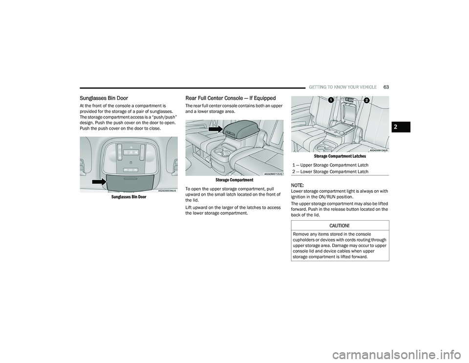
At the front of the console a compartment is
provided for the storage of a pair of sunglasses.
The storage compartment access is a “push/push”
design. Push the push cover on the door to open.
Push the push cover on the door to close.
Sunglasses Bin Door
Rear Full Center Console — If Equipped
The rear full center console contains both an upper
and a lower storage area.
Storage Compartment
To open the upper storage compartment, pull
upward on the small latch located on the front of
the lid.
Lift upward on the larger of the latches to access
the lower storage compartment.
Storage Compartment Latches
NOTE:Lower storage compartment light is always on with
ignition in the ON/RUN position.
The upper storage compartment may also be lifted
forward. Push in the release button located on the
back of the lid.
1 — Upper Storage Compartment Latch
2 — Lower Storage Compartment Latch
CAUTION!
Remove any items stored in the console
cupholders or devices with cords routing through
upper storage area. Damage may occur to upper
console lid and device cables when upper
storage compartment is lifted forward.
2
22_WD_OM_EN_USC_t.book Page 63
Page 71 of 332
GETTING TO KNOW YOUR VEHICLE69
WIRELESS CHARGING PAD —
I
F EQUIPPED
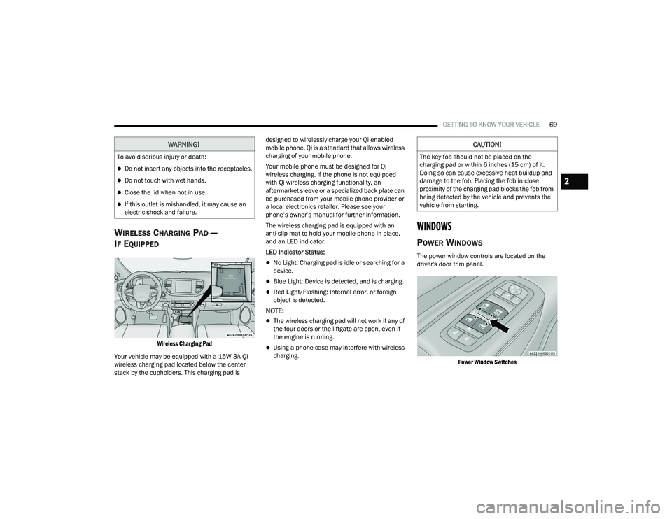
Wireless Charging Pad
Your vehicle may be equipped with a 15W 3A Qi
wireless charging pad located below the center
stack by the cupholders. This charging pad is designed to wirelessly charge your Qi enabled
mobile phone. Qi is a standard that allows wireless
charging of your mobile phone.
Your mobile phone must be designed for Qi
wireless charging. If the phone is not equipped
with Qi wireless charging functionality, an
aftermarket sleeve or a specialized back plate can
be purchased from your mobile phone provider or
a local electronics retailer. Please see your
phone’s owner’s manual for further information.
The wireless charging pad is equipped with an
anti-slip mat to hold your mobile phone in place,
and an LED indicator.
LED Indicator Status:
No Light: Charging pad is idle or searching for a
device.
Blue Light: Device is detected, and is charging.
Red Light/Flashing: Internal error, or foreign
object is detected.
NOTE:
The wireless charging pad will not work if any of
the four doors or the liftgate are open, even if
the engine is running.
Using a phone case may interfere with wireless
charging.
WINDOWS
POWER WINDOWS
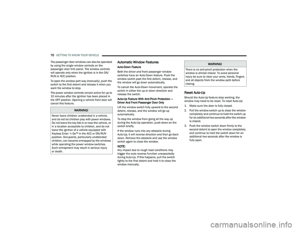
The power window controls are located on the
driver's door trim panel.
Power Window Switches
WARNING!
To avoid serious injury or death:
Do not insert any objects into the receptacles.
Do not touch with wet hands.
Close the lid when not in use.
If this outlet is mishandled, it may cause an
electric shock and failure.
CAUTION!
The key fob should not be placed on the
charging pad or within 6 inches (15 cm) of it.
Doing so can cause excessive heat buildup and
damage to the fob. Placing the fob in close
proximity of the charging pad blocks the fob from
being detected by the vehicle and prevents the
vehicle from starting.
2
22_WD_OM_EN_USC_t.book Page 69
Page 72 of 332
70GETTING TO KNOW YOUR VEHICLE
The passenger door windows can also be operated
by using the single window controls on the
passenger door trim panel. The window controls
will operate only when the ignition is in the ON/
RUN or ACC position.
To open the window part way (manually), push the
switch to the first detent and release it when you
want the window to stop.
The power window controls remain active for up to
10 minutes after the ignition has been placed in
the OFF position. Opening a vehicle front door will
cancel this feature.
Automatic Window Features
Auto-Down Feature
Both the driver and front passenger window
switches have an Auto-Down feature. Push the
window switch past the first detent, release, and
the window will go down automatically.
To cancel the Auto-Down movement, operate the
switch in either the up or down direction and
release the switch.
Auto-Up Feature With Anti-Pinch Protection —
Driver And Front Passenger Door Only
Lift the window switch fully upward to the second
detent, release, and the window will go up
automatically.
To stop the window from going all the way up
during the Auto-Up operation, push down on the
switch briefly.
If the window runs into any obstacle during
Auto-Up, it will reverse direction and then go back
down. Remove the obstacle and use the window
switch again to close the window.
NOTE:Any impact due to rough road conditions may
trigger the auto reverse function unexpectedly
during Auto-Up. If this happens, pull the switch
lightly to the first detent and hold it to close the
window manually.
Reset Auto-Up
Should the Auto-Up feature stop working, the
window may need to be reset. To reset Auto-Up:
1. Make sure the door is fully closed.
2. Pull the window switch up to close the window completely and continue to hold the switch up
for an additional two seconds after the window
is closed.
3. Push the window switch down firmly to the second detent to open the window completely
and continue to hold the switch down for an
additional two seconds after the window is
fully open.
WARNING!
Never leave children unattended in a vehicle,
and do not let children play with power windows.
Do not leave the key fob in or near the vehicle, or
in a location accessible to children, and do not
leave the ignition of a vehicle equipped with
Keyless Enter ‘n Go™ in the ACC or ON/RUN
position. Occupants, particularly unattended
children, can become entrapped by the windows
while operating the power window switches.
Such entrapment may result in serious injury
or death.
WARNING!
There is no anti-pinch protection when the
window is almost closed. To avoid personal
injury be sure to clear your arms, hands, fingers
and all objects from the window path before
closing.
22_WD_OM_EN_USC_t.book Page 70
Page 73 of 332
GETTING TO KNOW YOUR VEHICLE71
Window Lockout Switch
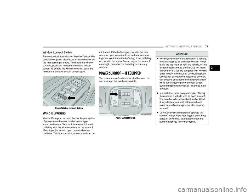
The window lockout switch on the driver's door trim
panel allows you to disable the window controls on
the rear passenger doors. To disable the window
controls, push and release the window lockout
button. To enable the window controls, push and
release the window lockout button again.
Power Window Lockout Switch
WIND BUFFETING
Wind buffeting can be described as the perception
of pressure on the ears or a helicopter-type
sound in the ears. Your vehicle may exhibit wind
buffeting with the windows down, or the sunroof
(if equipped) in certain open or partially open
positions. This is a normal occurrence and can be minimized. If the buffeting occurs with the rear
windows open, open the front and rear windows
together to minimize the buffeting. If the buffeting
occurs with the sunroof open, adjust the sunroof
opening to minimize the buffeting or open any
window.
POWER SUNROOF — IF EQUIPPED
The power sunroof switch is located between the
sun visors on the overhead console.
Power Sunroof Switch
WARNING!
Never leave children unattended in a vehicle,
or with access to an unlocked vehicle. Never
leave the key fob in or near the vehicle, or in a
location accessible to children. Do not leave
the ignition of a vehicle equipped with Keyless
Enter ‘n Go™ in the ACC or ON/RUN position.
Occupants, particularly unattended children,
can become entrapped by the power sunroof
while operating the power sunroof switch.
Such entrapment may result in serious injury
or death.
In a collision, there is a greater risk of being
thrown from a vehicle with an open sunroof.
You could also be seriously injured or killed.
Always fasten your seat belt properly and
make sure all passengers are also properly
secured.
Do not allow small children to operate the
sunroof. Never allow your fingers, other body
parts, or any object, to project through the
sunroof opening. Injury may result.
2
22_WD_OM_EN_USC_t.book Page 71
Page 83 of 332
GETTING TO KNOW YOUR INSTRUMENT PANEL81
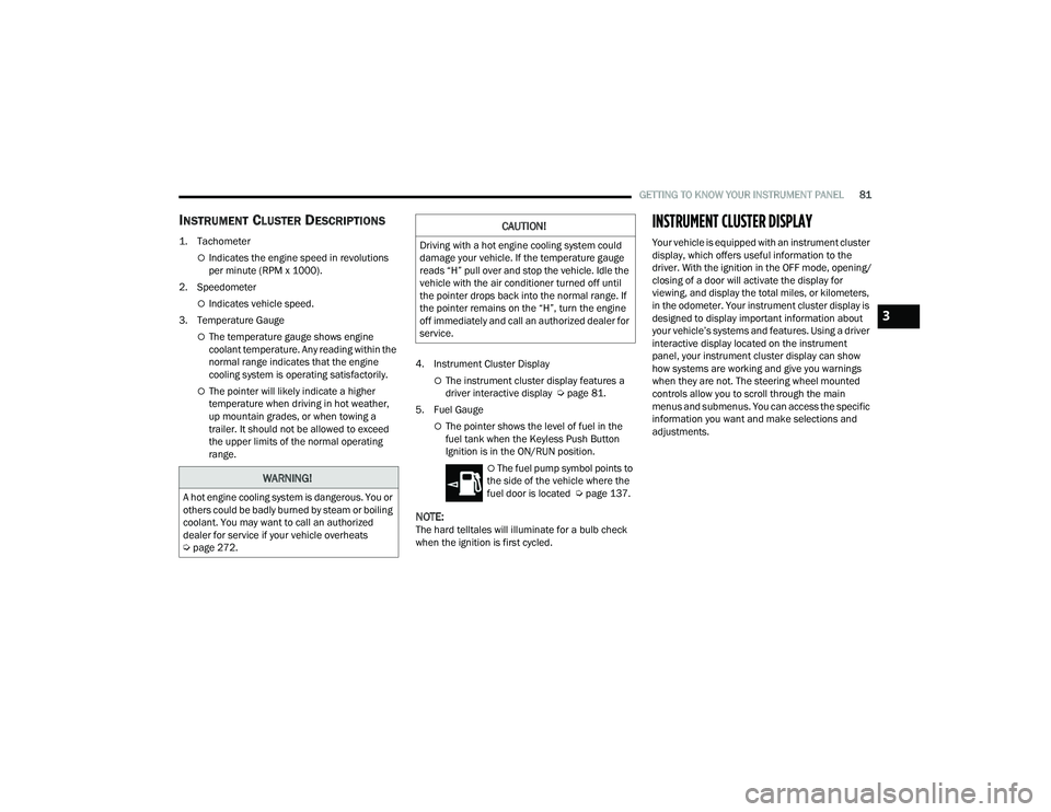
INSTRUMENT CLUSTER DESCRIPTIONS
1. Tachometer
Indicates the engine speed in revolutions
per minute (RPM x 1000).
2. Speedometer
Indicates vehicle speed.
3. Temperature Gauge
The temperature gauge shows engine
coolant temperature. Any reading within the
normal range indicates that the engine
cooling system is operating satisfactorily.
The pointer will likely indicate a higher
temperature when driving in hot weather,
up mountain grades, or when towing a
trailer. It should not be allowed to exceed
the upper limits of the normal operating
range. 4. Instrument Cluster DisplayThe instrument cluster display features a
driver interactive display Ú
page 81.
5. Fuel Gauge
The pointer shows the level of fuel in the
fuel tank when the Keyless Push Button
Ignition is in the ON/RUN position.
The fuel pump symbol points to
the side of the vehicle where the
fuel door is located Ú page 137.
NOTE:The hard telltales will illuminate for a bulb check
when the ignition is first cycled.
INSTRUMENT CLUSTER DISPLAY
Your vehicle is equipped with an instrument cluster
display, which offers useful information to the
driver. With the ignition in the OFF mode, opening/
closing of a door will activate the display for
viewing, and display the total miles, or kilometers,
in the odometer. Your instrument cluster display is
designed to display important information about
your vehicle’s systems and features. Using a driver
interactive display located on the instrument
panel, your instrument cluster display can show
how systems are working and give you warnings
when they are not. The steering wheel mounted
controls allow you to scroll through the main
menus and submenus. You can access the specific
information you want and make selections and
adjustments.
WARNING!
A hot engine cooling system is dangerous. You or
others could be badly burned by steam or boiling
coolant. You may want to call an authorized
dealer for service if your vehicle overheats
Úpage 272.
CAUTION!
Driving with a hot engine cooling system could
damage your vehicle. If the temperature gauge
reads “H” pull over and stop the vehicle. Idle the
vehicle with the air conditioner turned off until
the pointer drops back into the normal range. If
the pointer remains on the “H”, turn the engine
off immediately and call an authorized dealer for
service.
3
22_WD_OM_EN_USC_t.book Page 81
Page 85 of 332
GETTING TO KNOW YOUR INSTRUMENT PANEL83
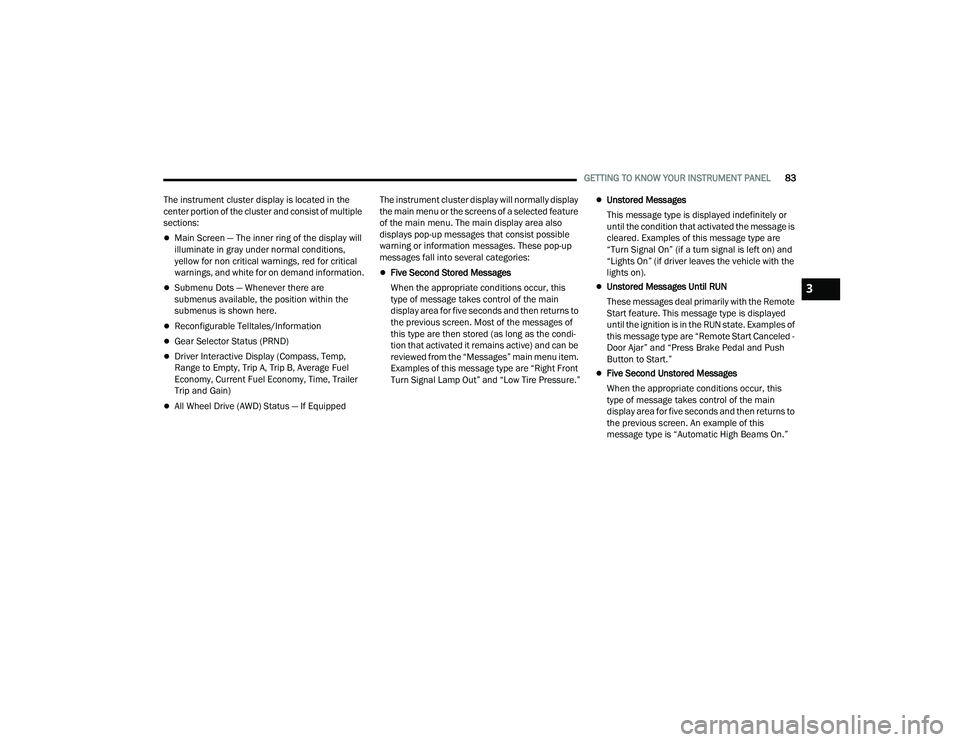
The instrument cluster display is located in the
center portion of the cluster and consist of multiple
sections:
Main Screen — The inner ring of the display will
illuminate in gray under normal conditions,
yellow for non critical warnings, red for critical
warnings, and white for on demand information.
Submenu Dots — Whenever there are
submenus available, the position within the
submenus is shown here.
Reconfigurable Telltales/Information
Gear Selector Status (PRND)
Driver Interactive Display (Compass, Temp,
Range to Empty, Trip A, Trip B, Average Fuel
Economy, Current Fuel Economy, Time, Trailer
Trip and Gain)
All Wheel Drive (AWD) Status — If Equipped The instrument cluster display will normally display
the main menu or the screens of a selected feature
of the main menu. The main display area also
displays pop-up messages that consist possible
warning or information messages. These pop-up
messages fall into several categories:
Five Second Stored Messages
When the appropriate conditions occur, this
type of message takes control of the main
display area for five seconds and then returns to
the previous screen. Most of the messages of
this type are then stored (as long as the condi-
tion that activated it remains active) and can be
reviewed from the “Messages” main menu item.
Examples of this message type are “Right Front
Turn Signal Lamp Out” and “Low Tire Pressure.”
Unstored Messages
This message type is displayed indefinitely or
until the condition that activated the message is
cleared. Examples of this message type are
“Turn Signal On” (if a turn signal is left on) and
“Lights On” (if driver leaves the vehicle with the
lights on).
Unstored Messages Until RUN
These messages deal primarily with the Remote
Start feature. This message type is displayed
until the ignition is in the RUN state. Examples of
this message type are “Remote Start Canceled -
Door Ajar” and “Press Brake Pedal and Push
Button to Start.”
Five Second Unstored Messages
When the appropriate conditions occur, this
type of message takes control of the main
display area for five seconds and then returns to
the previous screen. An example of this
message type is “Automatic High Beams On.”
3
22_WD_OM_EN_USC_t.book Page 83