run DODGE DURANGO 2022 User Guide
[x] Cancel search | Manufacturer: DODGE, Model Year: 2022, Model line: DURANGO, Model: DODGE DURANGO 2022Pages: 332, PDF Size: 19.82 MB
Page 29 of 332
GETTING TO KNOW YOUR VEHICLE27
Use the four-way control to adjust the steering
column.
NOTE:For vehicles equipped with Driver Memory Settings
Ú page 27, you can use your key fob or the
memory switch on the driver's door trim panel to
return the tilt/telescopic steering column to saved
positions.
HEATED STEERING WHEEL —
I
F EQUIPPED
The steering wheel contains a heating
element that helps warm your hands in
cold weather. The heated steering wheel
has only one temperature setting. Once
the heated steering wheel has been turned on, it
will stay on until the operator turns it off. The
heated steering wheel may not turn on when it is
already warm. The heated steering wheel control button is
located on the center stack below the radio screen,
or within the Uconnect system.
Push the heated steering wheel button once to
turn the heating element on.
Push the heated steering wheel button a second
time to turn the heating element off.
NOTE:The engine must be running for the heated
steering wheel to operate.
For information on use with the Remote Start
system, see Ú
page 20.
DRIVER MEMORY SETTINGS — IF EQUIPPED
This feature allows the driver to save up to two
different memory profiles for easy recall through a
memory switch. Each memory profile saves
desired position settings for the following features:
Driver seat
Easy Entry/Exit seat (if equipped)
Side mirrors
Power tilt and telescopic steering column
(if equipped)
A set of desired radio station presets
NOTE:
Your vehicle is equipped with two key fobs, each
can be linked to either memory position 1 or 2.
Be sure to program the radio presets prior to
programming the memory settings.
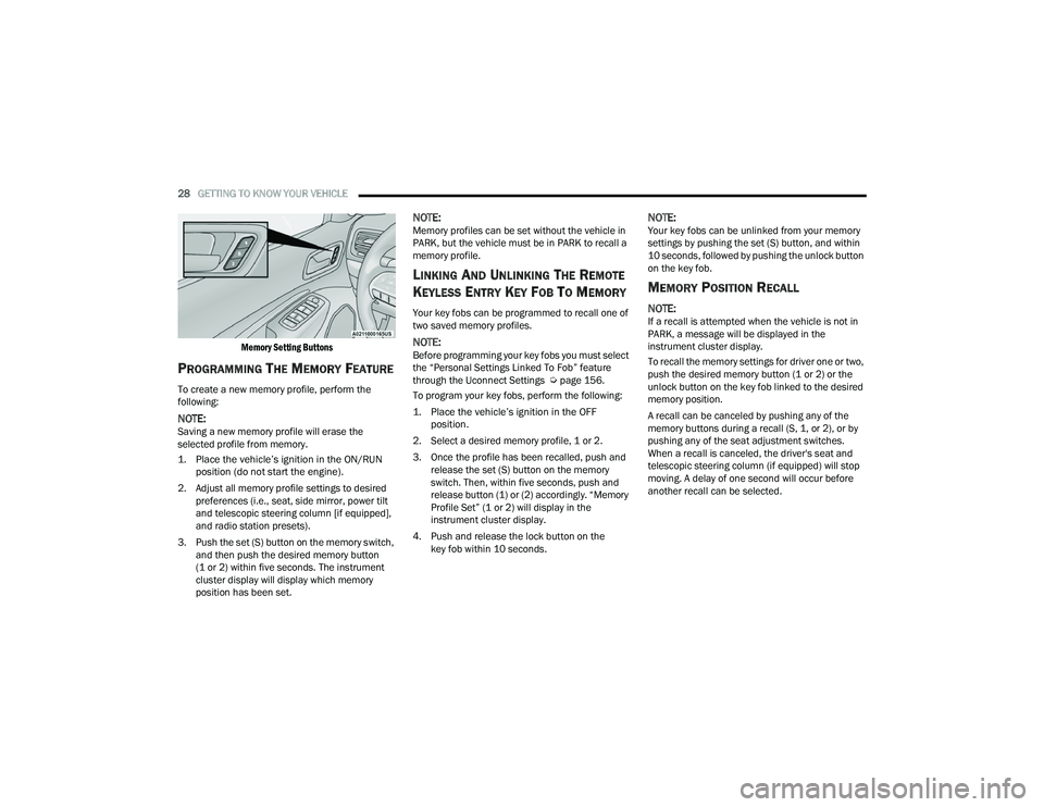
The memory setting switch is located on the
driver’s door trim panel. The switch consists of
three buttons:
The set (S) button, which is used to activate the
memory save function.
The (1) and (2) buttons which are used to recall
either of two saved memory profiles.
WARNING!
Do not adjust the steering column while driving.
Adjusting the steering column while driving or
driving with the steering column unlocked, could
cause the driver to lose control of the vehicle.
Failure to follow this warning may result in
serious injury or death.
WARNING!
Persons who are unable to feel pain to the
skin because of advanced age, chronic illness,
diabetes, spinal cord injury, medication,
alcohol use, exhaustion, or other physical
conditions must exercise care when using the
steering wheel heater. It may cause burns
even at low temperatures, especially if used
for long periods.
Do not place anything on the steering wheel
that insulates against heat, such as a blanket
or steering wheel covers of any type and mate -
rial. This may cause the steering wheel heater
to overheat.
2
22_WD_OM_EN_USC_t.book Page 27
Page 30 of 332
28GETTING TO KNOW YOUR VEHICLE
Memory Setting Buttons
PROGRAMMING THE MEMORY FEATURE
To create a new memory profile, perform the
following:
NOTE:Saving a new memory profile will erase the
selected profile from memory.
1. Place the vehicle’s ignition in the ON/RUN position (do not start the engine).
2. Adjust all memory profile settings to desired preferences (i.e., seat, side mirror, power tilt
and telescopic steering column [if equipped],
and radio station presets).
3. Push the set (S) button on the memory switch, and then push the desired memory button
(1 or 2) within five seconds. The instrument
cluster display will display which memory
position has been set.
NOTE:Memory profiles can be set without the vehicle in
PARK, but the vehicle must be in PARK to recall a
memory profile.
LINKING AND UNLINKING THE REMOTE
K
EYLESS ENTRY KEY FOB TO MEMORY
Your key fobs can be programmed to recall one of
two saved memory profiles.
NOTE:Before programming your key fobs you must select
the “Personal Settings Linked To Fob” feature
through the Uconnect Settings Ú page 156.
To program your key fobs, perform the following:
1. Place the vehicle’s ignition in the OFF position.
2. Select a desired memory profile, 1 or 2.
3. Once the profile has been recalled, push and release the set (S) button on the memory
switch. Then, within five seconds, push and
release button (1) or (2) accordingly. “Memory
Profile Set” (1 or 2) will display in the
instrument cluster display.
4. Push and release the lock button on the key fob within 10 seconds.
NOTE:Your key fobs can be unlinked from your memory
settings by pushing the set (S) button, and within
10 seconds, followed by pushing the unlock button
on the key fob.
MEMORY POSITION RECALL
NOTE:If a recall is attempted when the vehicle is not in
PARK, a message will be displayed in the
instrument cluster display.
To recall the memory settings for driver one or two,
push the desired memory button (1 or 2) or the
unlock button on the key fob linked to the desired
memory position.
A recall can be canceled by pushing any of the
memory buttons during a recall (S, 1, or 2), or by
pushing any of the seat adjustment switches.
When a recall is canceled, the driver's seat and
telescopic steering column (if equipped) will stop
moving. A delay of one second will occur before
another recall can be selected.
22_WD_OM_EN_USC_t.book Page 28
Page 37 of 332
GETTING TO KNOW YOUR VEHICLE35
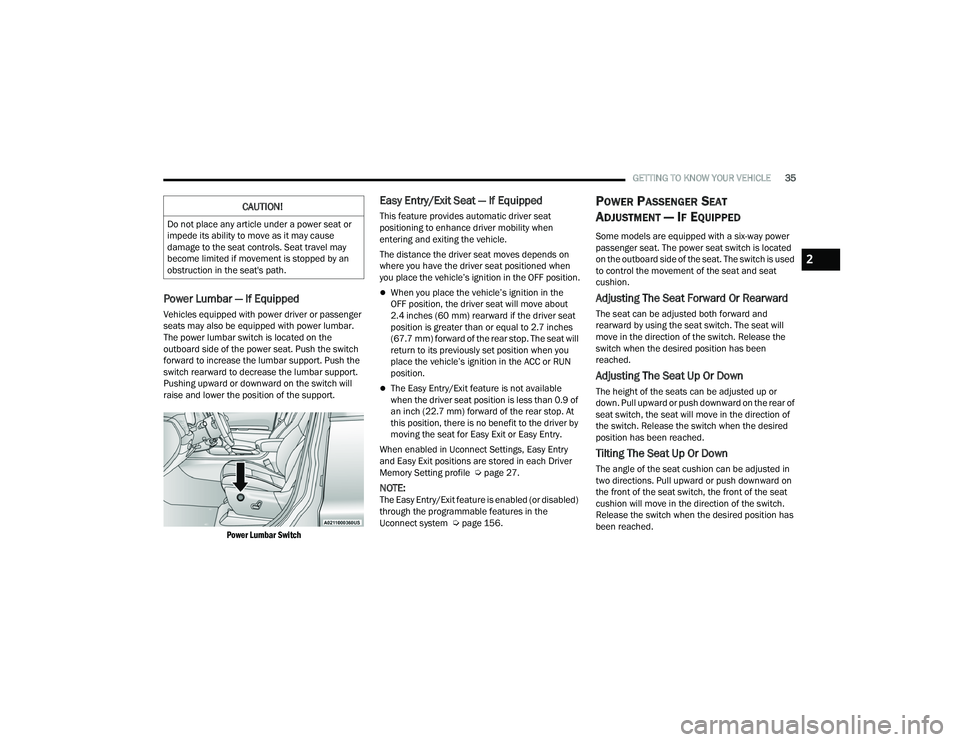
Power Lumbar — If Equipped
Vehicles equipped with power driver or passenger
seats may also be equipped with power lumbar.
The power lumbar switch is located on the
outboard side of the power seat. Push the switch
forward to increase the lumbar support. Push the
switch rearward to decrease the lumbar support.
Pushing upward or downward on the switch will
raise and lower the position of the support.
Power Lumbar Switch
Easy Entry/Exit Seat — If Equipped
This feature provides automatic driver seat
positioning to enhance driver mobility when
entering and exiting the vehicle.
The distance the driver seat moves depends on
where you have the driver seat positioned when
you place the vehicle’s ignition in the OFF position.
When you place the vehicle’s ignition in the
OFF position, the driver seat will move about
2.4 inches (60 mm) rearward if the driver seat
position is greater than or equal to 2.7 inches
(67.7 mm) forward of the rear stop. The seat will
return to its previously set position when you
place the vehicle’s ignition in the ACC or RUN
position.
The Easy Entry/Exit feature is not available
when the driver seat position is less than 0.9 of
an inch (22.7 mm) forward of the rear stop. At
this position, there is no benefit to the driver by
moving the seat for Easy Exit or Easy Entry.
When enabled in Uconnect Settings, Easy Entry
and Easy Exit positions are stored in each Driver
Memory Setting profile Ú page 27.
NOTE:The Easy Entry/Exit feature is enabled (or disabled)
through the programmable features in the
Uconnect system Úpage 156.
POWER PASSENGER SEAT
A
DJUSTMENT — IF EQUIPPED
Some models are equipped with a six-way power
passenger seat. The power seat switch is located
on the outboard side of the seat. The switch is used
to control the movement of the seat and seat
cushion.
Adjusting The Seat Forward Or Rearward
The seat can be adjusted both forward and
rearward by using the seat switch. The seat will
move in the direction of the switch. Release the
switch when the desired position has been
reached.
Adjusting The Seat Up Or Down
The height of the seats can be adjusted up or
down. Pull upward or push downward on the rear of
seat switch, the seat will move in the direction of
the switch. Release the switch when the desired
position has been reached.
Tilting The Seat Up Or Down
The angle of the seat cushion can be adjusted in
two directions. Pull upward or push downward on
the front of the seat switch, the front of the seat
cushion will move in the direction of the switch.
Release the switch when the desired position has
been reached.
CAUTION!
Do not place any article under a power seat or
impede its ability to move as it may cause
damage to the seat controls. Seat travel may
become limited if movement is stopped by an
obstruction in the seat's path.
2
22_WD_OM_EN_USC_t.book Page 35
Page 38 of 332
36GETTING TO KNOW YOUR VEHICLE
Reclining The Seatback
The angle of the seatback can be adjusted forward
or rearward. Push the seatback switch forward or
rearward, the seat will move in the direction of the
switch. Release the switch when the desired
position is reached.
Power Lumbar — If Equipped
The power lumbar switch is located on the
outboard side of the power seat. Push the switch
forward to increase the lumbar support. Push the
switch rearward to decrease the lumbar support.
Pushing upward or downward on the switch will
raise and lower the position of the support.
HEATED SEATS — IF EQUIPPED
Front Heated Seats — If Equipped
The front heated seats control buttons
are located on the center stack below the
radio screen, or within the Uconnect
system.
Push the heated seat switch once to turn the HI
setting on.
Push the heated seat switch a second time to
turn the MED setting on.
Push the heated seat switch a third time to turn
the LO setting on.
Push the heated seat switch a fourth time to
turn the heating elements off.
NOTE:
Once a heat setting is selected, heat will be felt
within two to five minutes.
The engine must be running for the heated
seats to operate.
The level of heat selected will stay on until the
operator changes it.
For information on use with the Remote Start
system, see Ú page 20.
WARNING!
Adjusting a seat while driving may be
dangerous. Moving a seat while driving could
result in loss of control which could cause a
collision and serious injury or death.
Seats should be adjusted before fastening the
seat belts and while the vehicle is parked.
Serious injury or death could result from a
poorly adjusted seat belt.
Do not ride with the seatback reclined so that
the shoulder belt is no longer resting against
your chest. In a collision you could slide under
the seat belt, which could result in serious
injury or death.
CAUTION!
Do not place any article under a power seat or
impede its ability to move as it may cause
damage to the seat controls. Seat travel may
become limited if movement is stopped by an
obstruction in the seat's path.
WARNING!
Persons who are unable to feel pain to the
skin because of advanced age, chronic illness,
diabetes, spinal cord injury, medication,
alcohol use, exhaustion or other physical
condition must exercise care when using the
seat heater. It may cause burns even at low
temperatures, especially if used for long
periods of time.
Do not place anything on the seat or seatback
that insulates against heat, such as a blanket
or cushion. This may cause the seat heater to
overheat. Sitting in a seat that has been over -
heated could cause serious burns due to the
increased surface temperature of the seat.
22_WD_OM_EN_USC_t.book Page 36
Page 39 of 332
GETTING TO KNOW YOUR VEHICLE37
Rear Heated Seats — If Equipped
The two second row outboard seats may
be equipped with heated seats. There
are two heated seat switches that allow
the rear passengers to operate the seats
independently. The heated seat switches for each
heater are located on the rear of the center
console.
You can choose from HI, LO, or off heat settings.
Amber indicator lights in each switch indicate the
level of heat in use. Two indicator lights will
illuminate for HI, one for LO and none for off.
Push the switch once to turn the HI setting on.
Push the switch a second time to turn the
LO setting on.
Push the switch a third time to turn the heating
elements off.
The level of heat selected will stay on until the
operator changes it.
NOTE:The engine must be running for the heated seats to
operate.
FRONT VENTILATED SEATS —
I
F EQUIPPED
The ventilated seats control buttons are
located on the center stack below the
radio screen, or within the Uconnect
system. The fans operate at three
speeds: HI, MED, and LO.
Push the ventilated seat switch once to
choose HI.
Push the ventilated seat switch a second time to
choose MED.
Push the ventilated seat switch a third time to
choose LO.
Push the ventilated seat switch a fourth time to
turn the ventilation off.
NOTE:The engine must be running for the ventilated
seats to operate.
For information on use with the Remote Start
system, see Ú page 20.
HEAD RESTRAINTS
Head restraints are designed to reduce the risk of
injury by restricting head movement in the event of
a rear impact. Head restraints should be adjusted
so that the top of the head restraint is located
above the top of your ear.
Front Head Restraints
Your vehicle is equipped with front four-way driver
and passenger head restraints.
To raise the head restraint, pull upward on the
head restraint. To lower the head restraint, push
the adjustment button, located at the base of the
head restraint, and push downward on the head
restraint.
WARNING!
All occupants, including the driver, should not
operate a vehicle or sit in a vehicle’s seat until
the head restraints are placed in their proper
positions in order to minimize the risk of neck
injury in the event of a crash.
Head restraints should never be adjusted
while the vehicle is in motion. Driving a vehicle
with the head restraints improperly adjusted
or removed could cause serious injury or
death in the event of a collision.
2
22_WD_OM_EN_USC_t.book Page 37
Page 45 of 332
GETTING TO KNOW YOUR VEHICLE43
UNIVERSAL GARAGE DOOR OPENER
(HOMELINK®)
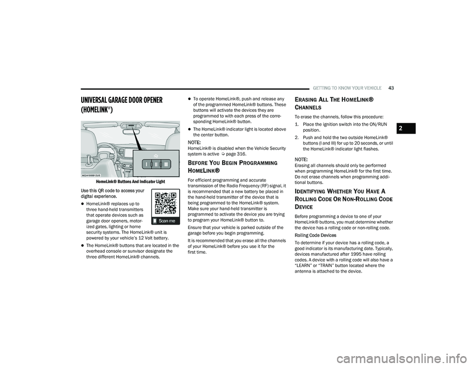
HomeLink® Buttons And Indicator Light
Use this QR code to access your
digital experience.
HomeLink® replaces up to
three hand-held transmitters
that operate devices such as
garage door openers, motor -
ized gates, lighting or home
security systems. The HomeLink® unit is
powered by your vehicle’s 12 Volt battery.
The HomeLink® buttons that are located in the
overhead console or sunvisor designate the
three different HomeLink® channels.
To operate HomeLink®, push and release any
of the programmed HomeLink® buttons. These
buttons will activate the devices they are
programmed to with each press of the corre -
sponding HomeLink® button.
The HomeLink® indicator light is located above
the center button.
NOTE:HomeLink® is disabled when the Vehicle Security
system is active Ú page 316.
BEFORE YOU BEGIN PROGRAMMING
H
OMELINK®
For efficient programming and accurate
transmission of the Radio Frequency (RF) signal, it
is recommended that a new battery be placed in
the hand-held transmitter of the device that is
being programmed to the HomeLink® system.
Make sure your hand-held transmitter is
programmed to activate the device you are trying
to program your HomeLink® button to.
Ensure that your vehicle is parked outside of the
garage before you begin programming.
It is recommended that you erase all the channels
of your HomeLink® before you use it for the
first time.
ERASING ALL THE HOMELINK®
C
HANNELS
To erase the channels, follow this procedure:
1. Place the ignition switch into the ON/RUN
position.
2. Push and hold the two outside HomeLink® buttons (I and III) for up to 20 seconds, or until
the HomeLink® indicator light flashes.
NOTE:Erasing all channels should only be performed
when programming HomeLink® for the first time.
Do not erase channels when programming addi -
tional buttons.
IDENTIFYING WHETHER YOU HAVE A
R
OLLING CODE OR NON-ROLLING CODE
D
EVICE
Before programming a device to one of your
HomeLink® buttons, you must determine whether
the device has a rolling code or non-rolling code.
Rolling Code Devices
To determine if your device has a rolling code, a
good indicator is its manufacturing date. Typically,
devices manufactured after 1995 have rolling
codes. A device with a rolling code will also have a
“LEARN” or “TRAIN” button located where the
antenna is attached to the device.
2
22_WD_OM_EN_USC_t.book Page 43
Page 46 of 332
44GETTING TO KNOW YOUR VEHICLE
The button may not be immediately visible when
looking at the device. The name and color of the
button may vary slightly by manufacturer.
NOTE:The “LEARN” or “TRAIN” button is not the button
you normally use to operate the device.
Non-rolling Code Devices
Most devices manufactured before 1995 will not
have a rolling code. These devices will also not
have a “LEARN” or “TRAIN” button.
PROGRAMMING HOMELINK® TO A
G
ARAGE DOOR OPENER
To program any of the HomeLink® buttons to
activate your garage door opener motor, refer to
the following steps:
NOTE:All HomeLink® buttons are programmed using this
procedure. You do not need to erase all channels
when programming additional buttons.
1. Place the ignition switch into the ON/RUN
position.
2. Place the garage door opener transmitter 1 to 3 inches (3 to 8 cm) away from the
HomeLink® button you wish to program,
while keeping the HomeLink® indicator light
in view. 3. Push and hold the HomeLink® button you
want to program while you push and hold the
garage door opener transmitter button you are
trying to replicate.
4. Continue to hold both buttons and observe the HomeLink® indicator light. The HomeLink®
indicator light will flash slowly and then rapidly.
Once this happens, release both buttons.
NOTE:Make sure the garage door opener motor is
plugged in before moving on to the rolling code/
non-rolling code final steps.
Rolling Code Garage Door Opener Final Steps
NOTE:You have 30 seconds in which to initiate rolling
code final step 2, after completing rolling code
final step 1.
1. At the garage door opener motor (in the garage), locate the “LEARN” or “TRAIN”
button. This can usually be found where the
hanging antenna wire is attached to the
garage door opener motor. Firmly push and
release the “LEARN” or “TRAIN” button.
2. Return to the vehicle and push the programmed HomeLink® button three times
(holding the button for two seconds each
time). If the garage door opener motor
operates, programming is complete. 3. Push the programmed HomeLink® button to
confirm that the garage door opener motor
operates. If the garage door opener motor
does not operate, repeat the final steps for the
rolling code procedure.
Non-Rolling Code Garage Door Opener Final Steps
1. Push and hold the programmed HomeLink® button and observe the HomeLink® indicator
light. If the HomeLink® indicator light stays
on constantly, programming is complete.
2. Push the programmed HomeLink® button to confirm that the garage door opener motor
operates. If the garage door opener motor
does not operate, repeat the steps from the
beginning.
WARNING!
Your motorized door or gate will open and close
while you are programming the universal trans -
ceiver. Do not program the transceiver if people
or pets are in the path of the door or gate.
Do not run your vehicle in a closed garage or
confined area while programming the trans -
ceiver. Exhaust gas from your vehicle contains
Carbon Monoxide (CO) which is odorless and
colorless. Carbon Monoxide is poisonous
when inhaled and can cause you and others to
be severely injured or killed.
22_WD_OM_EN_USC_t.book Page 44
Page 47 of 332
GETTING TO KNOW YOUR VEHICLE45
PROGRAMMING HOMELINK® TO A
M
ISCELLANEOUS DEVICE
The procedure on how to program HomeLink® to a
miscellaneous device follows the same procedure
as programming to a garage door opener
Ú page 44. Be sure to determine if the device has
a rolling code, or non-rolling code before beginning
the programming process.
NOTE:Canadian Radio Frequency (RF) laws require trans -
mitter signals to time-out (or quit) after several
seconds of transmission, which may not be long
enough for HomeLink® to pick up the signal during
programming. Similar to this Canadian law, some
U.S. gate operators are designed to time-out in the
same manner. The procedure may need to be
performed multiple times to successfully pair the
device to your HomeLink® buttons.
REPROGRAMMING A SINGLE
H
OMELINK® BUTTON
To reprogram a single HomeLink® button that has
been previously trained, without erasing all the
channels, refer to the following the procedure. Be
sure to determine whether the new device you
want to program the HomeLink® button to has a
rolling code, or non-rolling code.
1. Place the ignition to the ON/RUN position,
without starting the engine.
2. Push and hold the desired HomeLink® button until the HomeLink® indicator light begins to
flash after 20 seconds. Do not release the
button.
3. Without releasing the button , proceed with
Step 2 in “Programming HomeLink® To A
Garage Door Opener” and follow all remaining
steps.
CANADIAN/GATE OPERATOR
P
ROGRAMMING
For programming transmitters in Canada/United
States that require the transmitter signals to
“time-out” after several seconds of transmission:
Canadian Radio Frequency (RF) laws require
transmitter signals to time-out (or quit) after
several seconds of transmission, which may not be
long enough for HomeLink® to pick up the signal
during programming. Similar to this Canadian law,
some U.S. gate operators are designed to time-out
in the same manner.
It may be helpful to unplug the device during the
cycling process to prevent possible overheating of
the garage door or gate motor.
1. Place the ignition in the ON/RUN position.
NOTE:For vehicles equipped with Keyless Enter ‘n Go™,
place the ignition in the RUN position with the
engine on. Make sure while programming
HomeLink® with the engine on that your vehicle is
outside of your garage, or that the garage door
remains open at all times.
2. Place the hand-held transmitter 1 to 3 inches
(3 to 8 cm) away from the HomeLink® button
you wish to program while keeping the
HomeLink® indicator light in view.
3. Continue to push and hold the HomeLink® button while you push and release (cycle) your
hand-held transmitter every two seconds until
HomeLink® has successfully accepted the
frequency signal. The indicator light will flash
slowly and then rapidly when fully trained.
4. Watch for the HomeLink® indicator to change flash rates. When it changes, it is
programmed. It may take up to 30 seconds or
longer in rare cases. The garage door may
open and close while you are programming.
5. Push and hold the programmed HomeLink® button and observe the indicator light.
2
22_WD_OM_EN_USC_t.book Page 45
Page 48 of 332
46GETTING TO KNOW YOUR VEHICLE
NOTE:
If the indicator light stays on constantly,
programming is complete and the garage
door/device should activate when the
HomeLink® button is pushed.
To program the two remaining HomeLink®
buttons, repeat each step for each
remaining button. DO NOT erase the chan -
nels.
If you unplugged the garage door opener/device
for programming, plug it back in at this time.
Reprogramming A Single HomeLink® Button
(Canadian/Gate Operator)
To reprogram a channel that has been previously
trained, follow these steps:
1. Place the ignition in the ON/RUN position.
2. Press and hold the desired HomeLink® button until the indicator light begins to flash after
20 seconds. Do not release the button.
3. Without releasing the button, proceed with “Canadian/Gate Operator Programming”
Step 2 and follow all remaining steps.
SECURITY
It is advised to erase all channels before you sell or
turn in your vehicle.
To do this, push and hold the two outside buttons
for 20 seconds until the indicator flashes.
NOTE:All channels will be erased. Individual channels
cannot be erased.
The HomeLink® Universal Transceiver is disabled
when the Vehicle Security system is active.
TROUBLESHOOTING TIPS
If you are having trouble programming
HomeLink®, here are some of the most common
solutions:
Replace the battery in the garage door opener
hand-held transmitter.
Push the LEARN button on the garage door
opener to complete the training for a rolling
code.
Did you unplug the device for programming and
remember to plug it back in? If you have any problems, or require assistance,
please call toll-free 1-800-355-3515 or, on the
Internet at
HomeLink.com for information or
assistance.
WARNING!
Vehicle exhaust contains carbon monoxide, a
dangerous gas. Do not run your vehicle in the
garage while programming the transceiver.
Exhaust gas can cause serious injury or death.
Your motorized door or gate will open and
close while you are programming the universal
transceiver. Do not program the transceiver if
people, pets or other objects are in the path of
the door or gate. Only use this transceiver with
a garage door opener that has a “stop and
reverse” feature as required by Federal safety
standards. This includes most garage door
opener models manufactured after 1982.
Do not use a garage door opener without
these safety features.
22_WD_OM_EN_USC_t.book Page 46
Page 49 of 332
GETTING TO KNOW YOUR VEHICLE47
EXTERIOR LIGHTS
MULTIFUNCTION LEVER
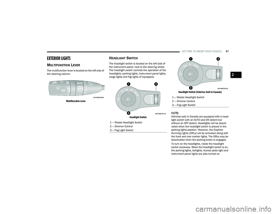
The multifunction lever is located on the left side of
the steering column.
Multifunction Lever
HEADLIGHT SWITCH
The headlight switch is located on the left side of
the instrument panel, next to the steering wheel.
The headlight switch controls the operation of the
headlights, parking lights, instrument panel lights,
cargo lights and fog lights (if equipped).
Headlight Switch Headlight Switch (Vehicles Sold In Canada)
NOTE:Vehicles sold in Canada are equipped with a head
-
light switch with an AUTO and ON detent but
without an OFF detent. Headlights will be deacti -
vated when the headlight switch is placed in the
parking lights position. However, the Daytime
Running Lights (DRLs) will be activated along with
the front and rear marker lights. The DRLs may be
deactivated when the parking brake is engaged.
To turn on the headlights, rotate the headlight
switch clockwise. When the headlight switch is on,
the parking lights, taillights, license plate light and
instrument panel lights are also turned on.
1 — Rotate Headlight Switch
2 — Dimmer Control
3 — Fog Light Switch
1 — Rotate Headlight Switch
2 — Dimmer Control
3 — Fog Light Switch
2
22_WD_OM_EN_USC_t.book Page 47