display DODGE DURANGO 2022 Workshop Manual
[x] Cancel search | Manufacturer: DODGE, Model Year: 2022, Model line: DURANGO, Model: DODGE DURANGO 2022Pages: 332, PDF Size: 19.82 MB
Page 134 of 332
132STARTING AND OPERATING
SERVICE THE PARKSENSE PARK ASSIST
S
YSTEM
During vehicle start up, when the ParkSense
System has detected a fault condition, the
instrument cluster will actuate a single chime,
once per ignition cycle, and it will display the
"PARKSENSE UNAVAILABLE WIPE REAR
SENSORS", "PARKSENSE UNAVAILABLE WIPE
FRONT SENSORS", or the "PARKSENSE
UNAVAILABLE SERVICE REQUIRED" message for
five seconds.
When the gear selector is moved to REVERSE and
the system has detected a fault condition, the
instrument cluster display will display a "PARKSENSE UNAVAILABLE WIPE REAR
SENSORS", "PARKSENSE UNAVAILABLE WIPE
FRONT SENSORS" or "PARKSENSE UNAVAILABLE
SERVICE REQUIRED" pop-up message for five
seconds. After five seconds, a vehicle graphic will
be displayed with "UNAVAILABLE" at either the
front or rear sensor location depending on where
the fault is detected. The system will continue to
provide arc alerts for the side that is functioning
properly. These arc alerts will interrupt the
"PARKSENSE UNAVAILABLE WIPE REAR
SENSORS", "PARKSENSE UNAVAILABLE WIPE
FRONT SENSORS", or "PARKSENSE UNAVAILABLE
SERVICE REQUIRED" messages if an object is
detected within the five second pop-up duration.
The vehicle graphic will remain displayed for as
long as the vehicle is in REVERSE.
If "PARKSENSE UNAVAILABLE WIPE REAR
SENSORS" or "PARKSENSE UNAVAILABLE WIPE
FRONT SENSORS" appears in the instrument
cluster display make sure the outer surface and
the underside of the rear fascia/bumper and/or
front fascia/bumper is clean and clear of snow,
ice, mud, dirt or other obstruction and then cycle
the ignition. If the message continues to appear
see an authorized dealer.
If the "PARKSENSE UNAVAILABLE SERVICE
REQUIRED" message appears in the instrument
cluster display, see an authorized dealer.
CLEANING THE PARKSENSE SYSTEM
Clean the ParkSense sensors with water, car wash
soap and a soft cloth. Do not use rough or hard
cloths. Do not scratch or poke the sensors.
PARKSENSE SYSTEM USAGE
P
RECAUTIONS
NOTE:
Ensure that the front and rear bumper are free
of snow, ice, mud, dirt and debris to keep the
ParkSense system operating properly.
Jackhammers, large trucks, and other vibra -
tions could affect the performance of Park -
Sense.
When you turn ParkSense off, the instrument
cluster will display “PARKSENSE OFF.” Further -
more, once you turn ParkSense off, it remains
off until you turn it on again, even if you cycle the
ignition.
When you move the gear selector to the
REVERSE position and ParkSense is turned off,
the instrument cluster will display “PARKSENSE
OFF” for as long as the vehicle is in REVERSE.
ParkSense, when on, will reduce the volume of
the radio when it is sounding a tone.
WARNING!
Before using ParkSense, it is strongly
recommended that the ball mount and hitch ball
assembly be disconnected from the vehicle
when the vehicle is not used for towing. Failure
to do so can result in injury or damage to
vehicles or obstacles because the hitch ball will
be much closer to the obstacle than the rear
fascia when the vehicle sounds the continuous
tone. Also, the sensors could detect the ball
mount and hitch ball assembly, depending on its
size and shape, giving a false indication that an
obstacle is behind the vehicle.
22_WD_OM_EN_USC_t.book Page 132
Page 135 of 332
STARTING AND OPERATING133
Clean the ParkSense sensors regularly, taking
care not to scratch or damage them. The
sensors must not be covered with ice, snow,
slush, mud, dirt or debris. Failure to do so can
result in the system not working properly. The
ParkSense system might not detect an obstacle
behind or in front of the fascia/bumper, or it
could provide a false indication that an obstacle
is behind or in front of the fascia/bumper.
Use the ParkSense switch to turn the ParkSense
system off if objects such as bicycle carriers,
trailer hitches, etc. are placed within 12 inches
(30 cm) of the rear fascia/bumper. Failure to do
so can result in the system misinterpreting a
close object as a sensor problem, causing the
“PARKSENSE UNAVAILABLE SERVICE
REQUIRED” message to be displayed in the
instrument cluster.
ParkSense should be disabled when the liftgate
is in the open position. An opened liftgate could
provide a false indication that an obstacle is
behind the vehicle.
LANESENSE — IF EQUIPPED
LANESENSE OPERATION
The LaneSense system is operational at speeds
above 37 mph (60 km/h) and below 112 mph
(180 km/h). The LaneSense system uses a
forward looking camera to detect lane markings
and measure vehicle position within the lane
boundaries.
WARNING!
Drivers must be careful when backing up even
when using ParkSense. Always check carefully
behind your vehicle, look behind you, and be
sure to check for pedestrians, animals, other
vehicles, obstructions, and blind spots before
backing up. You are responsible for safety and
must continue to pay attention to your
surroundings. Failure to do so can result in
serious injury or death.
Before using ParkSense, it is strongly recom -
mended that the ball mount and hitch ball
assembly be disconnected from the vehicle
when the vehicle is not used for towing.
Failure to do so can result in injury or damage
to vehicles or obstacles because the hitch ball
will be much closer to the obstacle than the
rear fascia when the vehicle sounds the
continuous tone. Also, the sensors could
detect the ball mount and hitch ball assembly,
depending on its size and shape, giving a false
indication that an obstacle is behind the
vehicle.
CAUTION!
ParkSense is only a parking aid and it is
unable to recognize every obstacle, including
small obstacles. Parking curbs might be
temporarily detected or not detected at all.
Obstacles located above or below the sensors
will not be detected when they are in close
proximity.
The vehicle must be driven slowly when using
ParkSense in order to be able to stop in time
when an obstacle is detected. It is recom -
mended that the driver looks over his/her
shoulder when using ParkSense.4
22_WD_OM_EN_USC_t.book Page 133
Page 136 of 332
134STARTING AND OPERATING
When both lane markings are detected and the
driver drifts out of the lane (no turn signal applied),
the LaneSense system provides a haptic warning
in the form of torque applied to the steering wheel
to prompt the driver to remain within the lane
boundaries. If the driver continues to drift out of
the lane, the LaneSense system provides a visual
warning through the instrument cluster display to
prompt the driver to remain within the lane
boundaries.
The driver may manually override the haptic
warning by applying force to the steering wheel at
any time.
When only a single lane marking is detected and
the driver drifts across the lane marking (no turn
signal applied), the LaneSense system provides
visual warnings through the instrument cluster
display to prompt the driver to remain within the
lane. When only a single lane marking is detected,
a haptic or a torque warning will not be provided.
NOTE:When operating conditions have been met, the
LaneSense system will monitor if the driver’s
hands are on the steering wheel and provide an
audible warning to the driver if removed. The
system will cancel if the driver does not return their
hands to the wheel.
TURNING LANESENSE ON OR OFF
The LaneSense button is located on the
switch panel below the Uconnect display.
To turn the LaneSense system on, push the
LaneSense button (LED turns off). A “LaneSense
On” message is shown in the instrument cluster
display.
To turn the LaneSense system off, push the
LaneSense button once (LED turns on).
NOTE:The LaneSense system will retain the last system
state on or off from the last ignition cycle when the
ignition is placed in the ON/RUN position.
LANESENSE WARNING MESSAGE
The LaneSense system will indicate the current
lane drift condition through the instrument cluster
display.
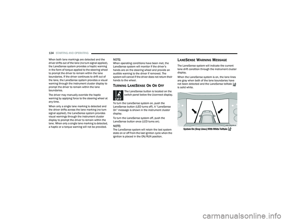
When the LaneSense system is on, the lane lines
are gray when both of the lane boundaries have
not been detected and the LaneSense telltale
is solid white.
System On (Gray Lines) With White Telltale
22_WD_OM_EN_USC_t.book Page 134
Page 137 of 332
STARTING AND OPERATING135
Left Lane Departure — Only Left Lane Detected
When the LaneSense system is on, the Lane-
Sense telltale is solid white when only the
left lane marking has been detected and the
system is ready to provide visual warnings in the
instrument cluster display if an unintentional
lane departure occurs.
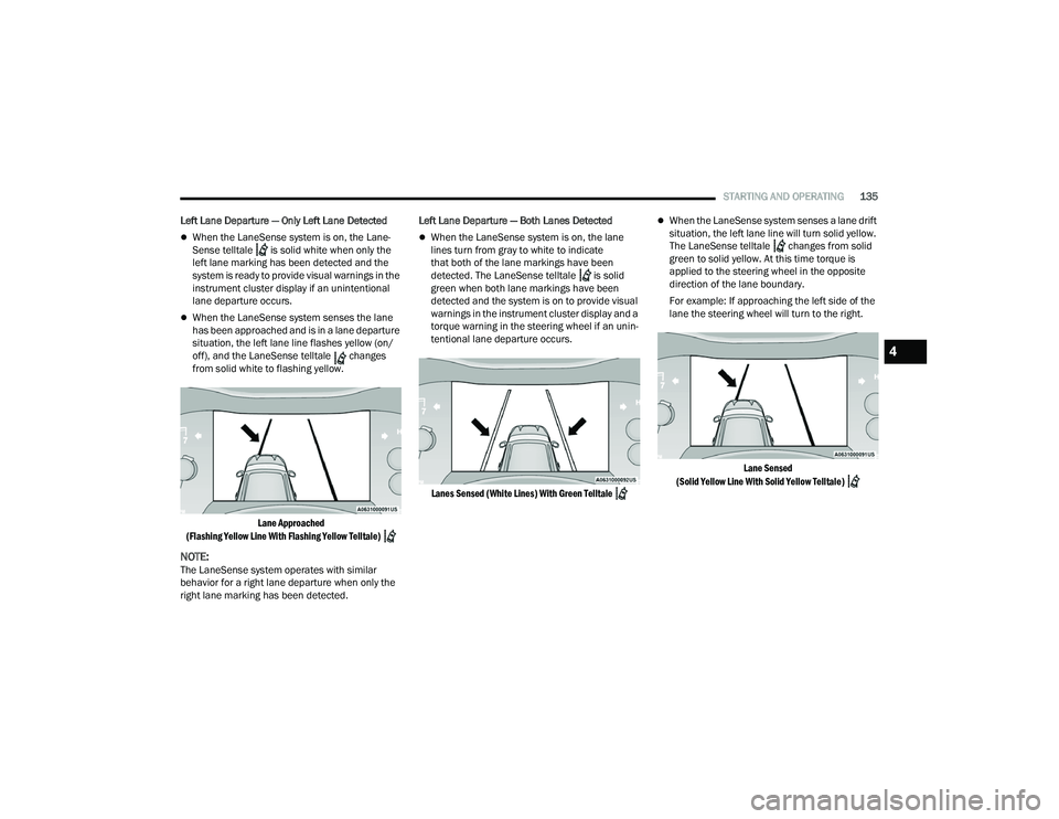
When the LaneSense system senses the lane
has been approached and is in a lane departure
situation, the left lane line flashes yellow (on/
off), and the LaneSense telltale changes
from solid white to flashing yellow.
Lane Approached
(Flashing Yellow Line With Flashing Yellow Telltale)
NOTE:The LaneSense system operates with similar
behavior for a right lane departure when only the
right lane marking has been detected. Left Lane Departure — Both Lanes Detected
When the LaneSense system is on, the lane
lines turn from gray to white to indicate
that both of the lane markings have been
detected. The LaneSense telltale is solid
green when both lane markings have been
detected and the system is on to provide visual
warnings in the instrument cluster display and a
torque warning in the steering wheel if an unin -
tentional lane departure occurs.
Lanes Sensed (White Lines) With Green Telltale
When the LaneSense system senses a lane drift
situation, the left lane line will turn solid yellow.
The LaneSense telltale changes from solid
green to solid yellow. At this time torque is
applied to the steering wheel in the opposite
direction of the lane boundary.
For example: If approaching the left side of the
lane the steering wheel will turn to the right.
Lane Sensed
(Solid Yellow Line With Solid Yellow Telltale)
4
22_WD_OM_EN_USC_t.book Page 135
Page 138 of 332
136STARTING AND OPERATING
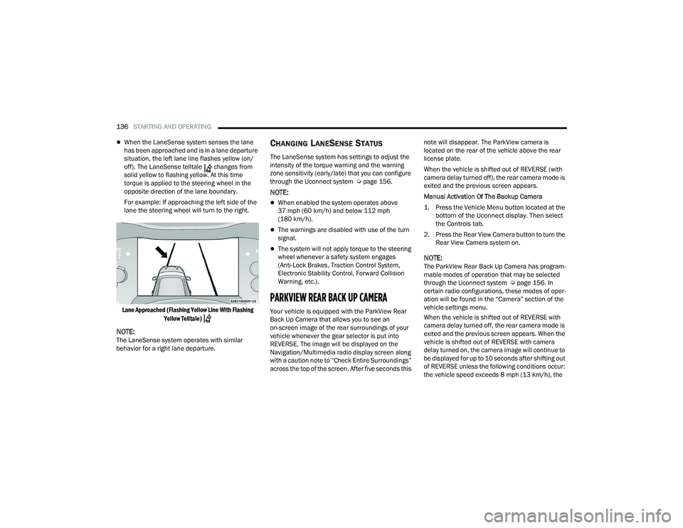
When the LaneSense system senses the lane
has been approached and is in a lane departure
situation, the left lane line flashes yellow (on/
off). The LaneSense telltale changes from
solid yellow to flashing yellow. At this time
torque is applied to the steering wheel in the
opposite direction of the lane boundary.
For example: If approaching the left side of the
lane the steering wheel will turn to the right.
Lane Approached (Flashing Yellow Line With Flashing Yellow Telltale)
NOTE:The LaneSense system operates with similar
behavior for a right lane departure.
CHANGING LANESENSE STATUS
The LaneSense system has settings to adjust the
intensity of the torque warning and the warning
zone sensitivity (early/late) that you can configure
through the Uconnect system Ú page 156.
NOTE:
When enabled the system operates above
37 mph (60 km/h) and below 112 mph
(180 km/h).
The warnings are disabled with use of the turn
signal.
The system will not apply torque to the steering
wheel whenever a safety system engages
(Anti-Lock Brakes, Traction Control System,
Electronic Stability Control, Forward Collision
Warning, etc.).
PARKVIEW REAR BACK UP CAMERA
Your vehicle is equipped with the ParkView Rear
Back Up Camera that allows you to see an
on-screen image of the rear surroundings of your
vehicle whenever the gear selector is put into
REVERSE. The image will be displayed on the
Navigation/Multimedia radio display screen along
with a caution note to “Check Entire Surroundings”
across the top of the screen. After five seconds this note will disappear. The ParkView camera is
located on the rear of the vehicle above the rear
license plate.
When the vehicle is shifted out of REVERSE (with
camera delay turned off), the rear camera mode is
exited and the previous screen appears.
Manual Activation Of The Backup Camera
1. Press the Vehicle Menu button located at the
bottom of the Uconnect display. Then select
the Controls tab.
2. Press the Rear View Camera button to turn the Rear View Camera system on.
NOTE:The ParkView Rear Back Up Camera has program -
mable modes of operation that may be selected
through the Uconnect system Ú page 156. In
certain radio configurations, these modes of oper -
ation will be found in the “Camera” section of the
vehicle settings menu.
When the vehicle is shifted out of REVERSE with
camera delay turned off, the rear camera mode is
exited and the previous screen appears. When the
vehicle is shifted out of REVERSE with camera
delay turned on, the camera image will continue to
be displayed for up to 10 seconds after shifting out
of REVERSE unless the following conditions occur:
the vehicle speed exceeds 8 mph (13 km/h), the
22_WD_OM_EN_USC_t.book Page 136
Page 139 of 332
STARTING AND OPERATING137
vehicle is shifted into PARK, the vehicle’s ignition is
placed in the OFF position, or the touchscreen X
button to disable the display of the Rear View
Camera is pressed.
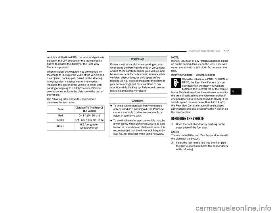
When enabled, active guidelines are overlaid on
the image to illustrate the width of the vehicle and
its projected backup path based on the steering
wheel position. A dashed center line overlay
indicates the center of the vehicle to assist with
parking or aligning to a hitch/receiver. Different
colored zones indicate the distance to the rear of
the vehicle.
The following table shows the approximate
distances for each zone:
NOTE:If snow, ice, mud, or any foreign substance builds
up on the camera lens, clean the lens, rinse with
water, and dry with a soft cloth. Do not cover the
lens.
Rear View Camera — Viewing At Speed When the vehicle is in PARK, NEUTRAL or
DRIVE, the Rear View Camera can be
activated with the Rear View Camera
button in the Controls tab of the Vehicle
Menu. This feature allows the customer to monitor
the area directly behind the vehicle (or trailer, if
equipped) for up to 10 seconds while driving. If the
vehicle speed remains below 8 mph (13 km/h),
the Rear View Camera image will be displayed
continuously until deactivated via the X button on
the touchscreen.
REFUELING THE VEHICLE
1. Open the fuel filler door by pushing on the outer edge of the fuel door.
NOTE:There is no fuel filler cap. Two flapper doors inside
the pipe seal the system.
2. Insert the fuel nozzle fully into the filler pipe – the nozzle opens and holds the flapper doors
while refueling.
Zone
Distance To The Rear Of
The Vehicle
Red 0 - 1 ft (0 - 30 cm)
Yellow 1 ft - 6.5 ft (30 cm - 2 m)
Green 6.5 ft or greater
(2 m or greater)
WARNING!
Drivers must be careful when backing up even
when using the ParkView Rear Back Up Camera.
Always check carefully behind your vehicle, and
be sure to check for pedestrians, animals, other
vehicles, obstructions, or blind spots before
backing up. You are responsible for the safety of
your surroundings and must continue to pay
attention while backing up. Failure to do so can
result in serious injury or death.
CAUTION!
To avoid vehicle damage, ParkView should
only be used as a parking aid. The ParkView
camera is unable to view every obstacle or
object in your drive path.
To avoid vehicle damage, the vehicle must be
driven slowly when using ParkView to be able
to stop in time when an obstacle is seen. It is
recommended that the driver look frequently
over his/her shoulder when using ParkView.
4
22_WD_OM_EN_USC_t.book Page 137
Page 148 of 332
146STARTING AND OPERATING
The user interface consists of the following:
Manual Brake Control Lever
Slide the manual brake control lever to the left to
activate power to the trailer's electric brakes
independent of the tow vehicle's brakes. If the
manual brake control lever is activated while the
brake is also applied, the greater of the two inputs
determines the power sent to the trailer brakes.
The trailer and the vehicle's brake lamps will come
on when either vehicle braking or manual trailer
brakes are applied.
Trailer Brake Status Indicator Light
This light indicates the trailer electrical connection
status.
If no electrical connection is detected after the
ignition is turned on, pushing the GAIN adjustment
button or sliding the manual brake control lever
will display the GAIN setting for 10 seconds and the
Trailer Brake Status Indicator Light will not be
displayed.
If a fault is detected in the trailer wiring or the
Integrated Trailer Brake Module (ITBM), the Trailer
Brake Status Indicator Light will flash. GAIN Adjustment Buttons (+/-)
Pushing these buttons will adjust the brake control
power output to the trailer brakes in
0.5 increments. The GAIN setting can be increased
to a maximum of 10 or decreased to a minimum of
0 (no trailer braking).
GAIN
The GAIN setting is used to set the trailer brake
control for the specific towing condition and should
be changed as towing conditions change. Changes
to towing conditions include trailer load, vehicle
load, road conditions and weather.
Adjusting GAIN
NOTE:This should only be performed in a traffic free envi
-
ronment at speeds of approximately 20–25 mph
(30–40 km/h).
1. Make sure the trailer brakes are in good working condition, functioning normally and
properly adjusted. See a trailer dealer if
necessary.
2. Hook up the trailer and make the electrical connections according to the trailer
manufacturer's instructions.
3. When a trailer with electric/EOH brakes is plugged in, the trailer connected message
should appear in the instrument cluster
display (if the connection is not recognized by the ITBM, braking functions will not be
available), the GAIN setting will illuminate and
the correct type of trailer must be selected
from the instrument cluster display options.
4. Push the UP or DOWN button on the steering wheel until “TRAILER TOW” appears on the
screen.
5. Push the RIGHT arrow on the steering wheel to enter “TRAILER TOW”.
6. Push the UP or DOWN buttons until the Trailer Brake Type appears on the screen.
7. Push the RIGHT arrow and then push the UP or DOWN buttons until the proper Trailer Brake
Type appears on the screen.
8. In a traffic-free environment, tow the trailer on a dry, level surface at a speed of 20–25 mph
(30–40 km/h) and squeeze the manual brake
control lever completely.
9. If the trailer wheels lockup (indicated by squealing tires), reduce the GAIN setting; if the
trailer wheels turn freely, increase the GAIN
setting.
Repeat steps 8 and 9 until the GAIN setting is
at a point just below trailer wheel lockup. If towing
a heavier trailer, trailer wheel lockup may not be
attainable even with the maximum GAIN setting
of 10.
22_WD_OM_EN_USC_t.book Page 146
Page 149 of 332
STARTING AND OPERATING147
Display Messages
The trailer brake control interacts with the
instrument cluster display. Display messages,
along with a single chime, will be displayed when a
malfunction is determined in the trailer
connection, trailer brake control, or on the trailer
Ú page 81.
NOTE:
An aftermarket controller may be available for
use with trailers with air or EOH trailer brake
systems. To determine the type of brakes on
your trailer and the availability of controllers,
check with your trailer manufacturer or dealer.
Removal of the ITBM will cause errors and it
may cause damage to the electrical system and
electronic modules of the vehicle. See an autho -
rized dealer if an aftermarket module is to be
installed.
Towing Requirements — Trailer Lights And
Wiring
Whenever pulling a trailer, regardless of the trailer
size, stoplights and turn signals on the trailer are
required for motoring safety.
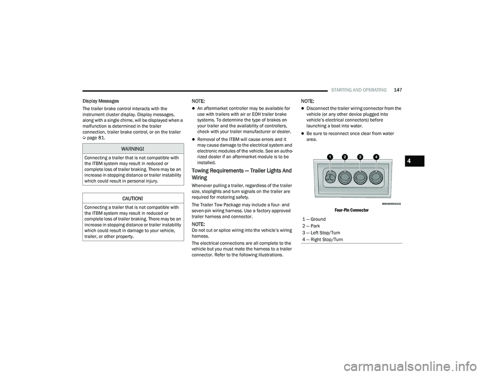
The Trailer Tow Package may include a four- and
seven-pin wiring harness. Use a factory approved
trailer harness and connector.
NOTE:Do not cut or splice wiring into the vehicle’s wiring
harness.
The electrical connections are all complete to the
vehicle but you must mate the harness to a trailer
connector. Refer to the following illustrations.
NOTE:
Disconnect the trailer wiring connector from the
vehicle (or any other device plugged into
vehicle’s electrical connectors) before
launching a boat into water.
Be sure to reconnect once clear from water
area.
Four-Pin Connector
WARNING!
Connecting a trailer that is not compatible with
the ITBM system may result in reduced or
complete loss of trailer braking. There may be an
increase in stopping distance or trailer instability
which could result in personal injury.
CAUTION!
Connecting a trailer that is not compatible with
the ITBM system may result in reduced or
complete loss of trailer braking. There may be an
increase in stopping distance or trailer instability
which could result in damage to your vehicle,
trailer, or other property.
1 — Ground
2 — Park
3 — Left Stop/Turn
4 — Right Stop/Turn
4
22_WD_OM_EN_USC_t.book Page 147
Page 158 of 332
156
MULTIMEDIA
UCONNECT SYSTEMS
For detailed information about your Uconnect 4
With 8.4-inch Display or Uconnect 5 NAV With
10.1-inch Display systems, refer to your Uconnect
Owner’s Manual Supplement.
NOTE:Uconnect screen images are for illustration
purposes only and may not reflect exact software
for your vehicle.
CYBERSECURITY
Your vehicle may be a connected vehicle and may
be equipped with both wired and wireless
networks. These networks allow your vehicle to
send and receive information. This information
allows systems and features in your vehicle to
function properly.
Your vehicle may be equipped with certain security
features to reduce the risk of unauthorized and
unlawful access to vehicle systems and wireless
communications. Vehicle software technology
continues to evolve over time and FCA US LLC,
working with its suppliers, evaluates and takes
appropriate steps as needed. Similar to a
computer or other devices, your vehicle may require software updates to improve the usability
and performance of your systems or to reduce the
potential risk of unauthorized and unlawful access
to your vehicle systems.
The risk of unauthorized and unlawful access to
your vehicle systems may still exist, even if the
most recent version of vehicle software (such as
Uconnect software) is installed.
NOTE:
FCA US LLC or your dealer may contact you
directly regarding software updates.
To help further improve vehicle security and
minimize the potential risk of a security breach,
vehicle owners should:
Routinely check www.driveuconnect.com
(US Residents) or www.driveuconnect.ca
(Canadian Residents) to learn about avail -
able Uconnect software updates.
Only connect and use trusted media
devices (e.g. personal mobile phones,
USBs, CDs).
UCONNECT SETTINGS
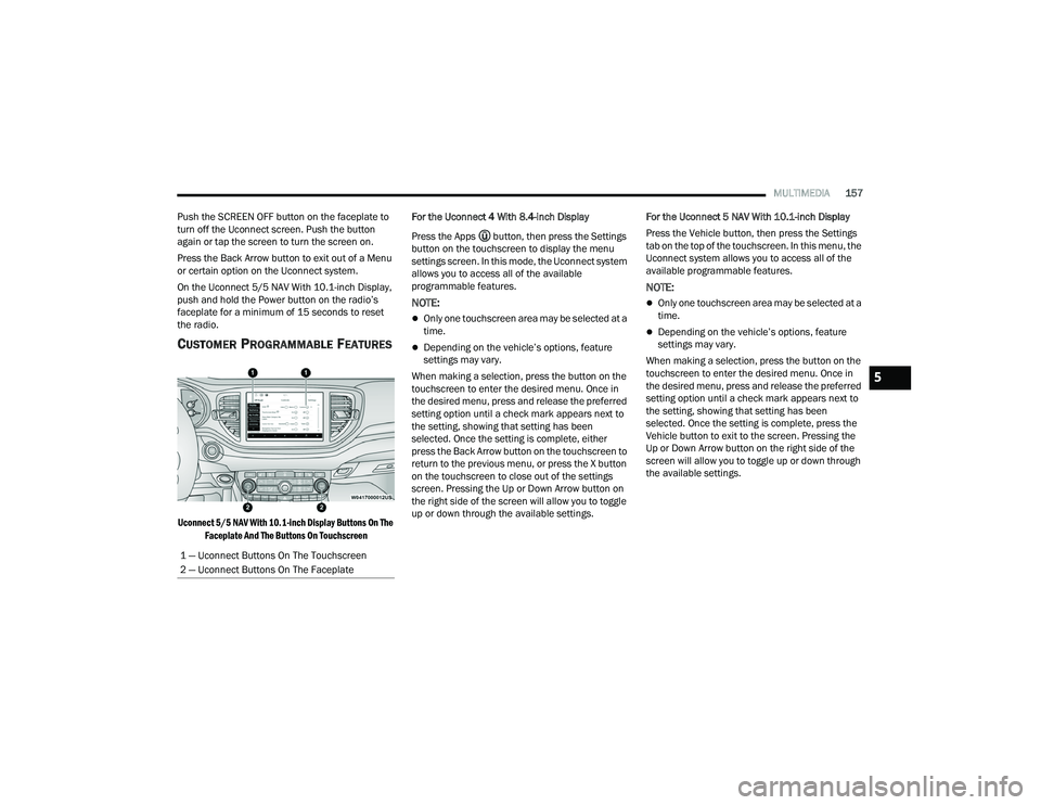
The Uconnect system uses a combination of
buttons on the touchscreen and buttons on the
faceplate located on the center of the instrument
panel. These buttons allow you to access and
change the customer programmable features.
Many features can vary by vehicle.
Buttons on the faceplate are located below and/or
beside the Uconnect system in the center of the
instrument panel. In addition, there is a SCROLL/
ENTER control knob located on the right side. Turn
the control knob to scroll through menus and
change settings. Push the center of the control
knob one or more times to select or change a
setting.
Your Uconnect system may also have SCREEN OFF
and MUTE buttons on the faceplate.WARNING!
ONLY insert trusted devices/components into
your vehicle. Media of unknown origin could
possibly contain malicious software, and if
installed in your vehicle, it may increase the
possibility for vehicle systems to be breached.
As always, if you experience unusual vehicle
behavior, take your vehicle to your nearest
authorized dealer immediately.
22_WD_OM_EN_USC_t.book Page 156
Page 159 of 332
MULTIMEDIA157
Push the SCREEN OFF button on the faceplate to
turn off the Uconnect screen. Push the button
again or tap the screen to turn the screen on.
Press the Back Arrow button to exit out of a Menu
or certain option on the Uconnect system.
On the Uconnect 5/5 NAV With 10.1-inch Display,
push and hold the Power button on the radio’s
faceplate for a minimum of 15 seconds to reset
the radio.
CUSTOMER PROGRAMMABLE FEATURES
Uconnect 5/5 NAV With 10.1-inch Display Buttons On The Faceplate And The Buttons On Touchscreen
For the Uconnect 4 With 8.4-inch Display
Press the Apps button, then press the Settings
button on the touchscreen to display the menu
settings screen. In this mode, the Uconnect system
allows you to access all of the available
programmable features.
NOTE:
Only one touchscreen area may be selected at a
time.
Depending on the vehicle’s options, feature
settings may vary.
When making a selection, press the button on the
touchscreen to enter the desired menu. Once in
the desired menu, press and release the preferred
setting option until a check mark appears next to
the setting, showing that setting has been
selected. Once the setting is complete, either
press the Back Arrow button on the touchscreen to
return to the previous menu, or press the X button
on the touchscreen to close out of the settings
screen. Pressing the Up or Down Arrow button on
the right side of the screen will allow you to toggle
up or down through the available settings. For the Uconnect 5 NAV With 10.1-inch Display
Press the Vehicle button, then press the Settings
tab on the top of the touchscreen. In this menu, the
Uconnect system allows you to access all of the
available programmable features.
NOTE:
Only one touchscreen area may be selected at a
time.
Depending on the vehicle’s options, feature
settings may vary.
When making a selection, press the button on the
touchscreen to enter the desired menu. Once in
the desired menu, press and release the preferred
setting option until a check mark appears next to
the setting, showing that setting has been
selected. Once the setting is complete, press the
Vehicle button to exit to the screen. Pressing the
Up or Down Arrow button on the right side of the
screen will allow you to toggle up or down through
the available settings.
1 — Uconnect Buttons On The Touchscreen
2 — Uconnect Buttons On The Faceplate
5
22_WD_OM_EN_USC_t.book Page 157