display DODGE DURANGO 2022 Manual Online
[x] Cancel search | Manufacturer: DODGE, Model Year: 2022, Model line: DURANGO, Model: DODGE DURANGO 2022Pages: 332, PDF Size: 19.82 MB
Page 185 of 332
SAFETY183
If the ABS Warning Light is on, the brake system
should be serviced as soon as possible to restore
the benefits of Anti-Lock Brakes. If the ABS
Warning Light does not come on when the ignition
is placed in the ON/RUN mode, have the light
repaired as soon as possible.
REAR SEAT REMINDER ALERT (RSRA)
RSRA will consider the presence of an object in the
rear seat when a rear entry/exit door is opened at
the beginning of each key cycle. To activate, the
rear door must be open for more than one second
and the vehicle must be placed in the ON/RUN
position within 10 minutes. When the potential
presence of an object is determined and/or
otherwise inferred, a message will appear in the
instrument cluster display reminding driver to
check the rear seat(s) immediately after key off
accompanied by an alert upon exiting the vehicle.
To enable or disable RSRA, see Ú page 156.
ELECTRONIC BRAKE CONTROL (EBC)
S
YSTEM
Your vehicle is equipped with an advanced
Electronic Brake Control (EBC) system. This system
includes Anti-Lock Brake System (ABS), Brake
Assist System (BAS), Electronic Brake Force
Distribution (EBD), Electronic Roll Mitigation
(ERM), Electronic Stability Control (ESC), Hill Start
Assist (HSA), and Traction Control System (TCS). These systems work together to enhance both
vehicle stability and control in various driving
conditions.
Your vehicle may also be equipped with Dynamic
Steering Torque (DST), Rain Brake Support (RBS),
Ready Alert Braking (RAB), and Trailer Sway
Control (TSC).
Brake Assist System (BAS)
The BAS is designed to optimize the vehicle’s
braking capability during emergency braking
maneuvers. The system detects an emergency
braking situation by sensing the rate and amount
of brake application and then applies optimum
pressure to the brakes. This can help reduce
braking distances. The BAS complements the
Anti-Lock Brake System (ABS). Applying the brakes
very quickly results in the best BAS assistance. To
receive the benefit of the system, you must apply
continuous braking pressure during the stopping
sequence (do not “pump” the brakes). Do not
reduce brake pedal pressure unless braking is no
longer desired. Once the brake pedal is released,
the BAS is deactivated.
Brake System Warning Light
The red Brake System Warning Light will turn on
when the ignition is placed in the ON/RUN mode
and may stay on for as long as four seconds.
If the Brake System Warning Light remains on or
comes on while driving, it indicates that the brake
system is not functioning properly and that
immediate service is required. If the Brake System
Warning Light does not come on when the ignition
is placed in the ON/RUN mode, have the light
repaired as soon as possible.
WARNING!
The Brake Assist System (BAS) cannot prevent
the natural laws of physics from acting on the
vehicle, nor can it increase the traction afforded
by prevailing road conditions. BAS cannot
prevent collisions, including those resulting from
excessive speed in turns, driving on very slippery
surfaces, or hydroplaning. The capabilities of a
BAS-equipped vehicle must never be exploited in
a reckless or dangerous manner, which could
jeopardize the user's safety or the safety of
others.
6
22_WD_OM_EN_USC_t.book Page 183
Page 190 of 332
188SAFETY
AUXILIARY DRIVING SYSTEMS
BLIND SPOT MONITORING (BSM) —
I
F EQUIPPED
BSM uses two radar sensors, located inside the
rear fascia/bumper, to detect highway licensable
vehicles (automobiles, trucks, motorcycles, etc.)
that enter the blind spot zones from the rear/front/
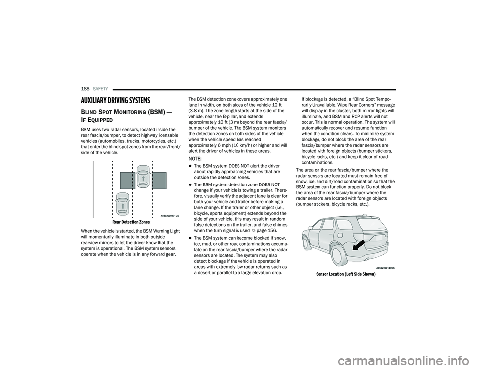
side of the vehicle.
Rear Detection Zones
When the vehicle is started, the BSM Warning Light
will momentarily illuminate in both outside
rearview mirrors to let the driver know that the
system is operational. The BSM system sensors
operate when the vehicle is in any forward gear. The BSM detection zone covers approximately one
lane in width, on both sides of the vehicle 12 ft
(3.8 m). The zone length starts at the side of the
vehicle, near the B-pillar, and extends
approximately 10 ft (3 m) beyond the rear fascia/
bumper of the vehicle. The BSM system monitors
the detection zones on both sides of the vehicle
when the vehicle speed has reached
approximately 6 mph (10 km/h) or higher and will
alert the driver of vehicles in these areas.
NOTE:
The BSM system DOES NOT alert the driver
about rapidly approaching vehicles that are
outside the detection zones.
The BSM system detection zone DOES NOT
change if your vehicle is towing a trailer. There
-
fore, visually verify the adjacent lane is clear for
both your vehicle and trailer before making a
lane change. If the trailer or other object (i.e.,
bicycle, sports equipment) extends beyond the
side of your vehicle, this may result in random
false detections on the trailer, and false chimes
when the turn signal is used Ú page 156.
The BSM system can become blocked if snow,
ice, mud, or other road contaminations accumu -
late on the rear fascia/bumper where the radar
sensors are located. The system may also
detect blockage if the vehicle is operated in
areas with extremely low radar returns such as
a desert or parallel to a large elevation drop. If blockage is detected, a “Blind Spot Tempo-
rarily Unavailable, Wipe Rear Corners” message
will display in the cluster, both mirror lights will
illuminate, and BSM and RCP alerts will not
occur. This is normal operation. The system will
automatically recover and resume function
when the condition clears. To minimize system
blockage, do not block the area of the rear
fascia/bumper where the radar sensors are
located with foreign objects (bumper stickers,
bicycle racks, etc.) and keep it clear of road
contaminations.
The area on the rear fascia/bumper where the
radar sensors are located must remain free of
snow, ice, and dirt/road contamination so that the
BSM system can function properly. Do not block
the area of the rear fascia/bumper where the
radar sensors are located with foreign objects
(bumper stickers, bicycle racks, etc.).
Sensor Location (Left Side Shown)
22_WD_OM_EN_USC_t.book Page 188
Page 193 of 332
SAFETY191
NOTE:
In a parking lot situation, oncoming vehicles can be
blocked by vehicles parked on either side. If the
sensors are blocked by other structures or vehicles,
the system will not be able to alert the driver.
Blind Spot Modes
Blind Spot has three selectable modes of
operation that are available in the Uconnect
system.
Blind Spot Alert Lights Only
When operating in Blind Spot Alert mode, the BSM
system will provide a visual alert in the appropriate
side view mirror based on a detected object.
However, when the system is operating in Rear
Cross Path (RCP) mode, the system will respond with both visual and audible alerts when a
detected object is present. Whenever an audible
alert is requested, the radio is muted.
Blind Spot Alert Lights/Chime
When operating in Blind Spot Alert Lights/Chime
mode, the BSM system will provide a visual alert in
the appropriate side view mirror based on a
detected object. If the turn signal is then activated,
and it corresponds to an alert present on that side
of the vehicle, an audible chime will also be
sounded. Whenever a turn signal and detected
object are present on the same side at the same
time, both the visual and audible alerts will be
issued. In addition to the audible alert the radio (if
on) will also be muted.
NOTE:Whenever an audible alert is requested by the
BSM system, the radio is also muted.
When the system is in RCP, the system shall
respond with both visual and audible alerts when a
detected object is present. Whenever an audible
alert is requested, the radio is also muted. Turn/
hazard signal status is ignored; the RCP state
always requests the chime.
Blind Spot Alert Off
When the BSM system is turned off there will be
no visual or audible alerts from either the BSM or
RCP systems.
NOTE:The BSM system will store the current operating
mode when the vehicle is shut off. Each time the
vehicle is started the previously stored mode will
be recalled and used.
FORWARD COLLISION WARNING (FCW)
W
ITH MITIGATION
FCW with Mitigation provides the driver with
audible warnings, visual warnings (within the
instrument cluster display), and may apply a brake
jerk to warn the driver when it detects a potential
frontal collision. The warnings and limited braking
are intended to provide the driver with enough time
to react, avoid or mitigate the potential collision.
NOTE:FCW monitors the information from the forward
looking sensors as well as the Electronic Brake
Controller (EBC) to calculate the probability of a
forward collision. When the system determines
that a forward collision is probable, the driver will
be provided with audible and visual warnings and
may provide a brake jerk warning. If the driver does
not take action based upon these progressive
warnings, then the system will provide a limited
level of active braking to help slow the vehicle and
mitigate the potential forward collision. If the driver
reacts to the warnings by braking and the system
WARNING!
Rear Cross Path (RCP) detection is not a backup
aid system. It is intended to be used to help a
driver detect an oncoming vehicle in a parking
lot situation. Drivers must be careful when
backing up, even when using RCP. Always check
carefully behind your vehicle, look behind you,
and be sure to check for pedestrians, animals,
other vehicles, obstructions, and blind spots
before backing up. Failure to do so can result in
serious injury or death.
6
22_WD_OM_EN_USC_t.book Page 191
Page 195 of 332
SAFETY193
NOTE:
Changing the FCW status to “Only Warning”
prevents the system from providing limited
active braking, or additional brake support if the
driver is not braking adequately in the event of
a potential frontal collision, but maintains the
audible and visual warnings.
Changing the FCW status to “Off” prevents the
system from providing autonomous braking, or
additional brake support if the driver is not
braking adequately in the event of a potential
frontal collision.
The system will retain the last setting selected
by the driver after ignition shut down.
FCW may not react to irrelevant objects such as
overhead objects, ground reflections, objects
not in the path of the vehicle, stationary objects
that are far away, oncoming traffic, or leading
vehicles with the same or higher rate of speed.
FCW will be disabled like ACC, with the unavail -
able screens.
FCW Limited Warning
If the instrument cluster displays “ACC/FCW
Limited Functionality” or “ACC/FCW Limited
Functionality Clean Front Windshield”
momentarily, there may be a condition that limits
FCW functionality. Although the vehicle is still
drivable under normal conditions, the active
braking may not be fully available. Once the condition that limited the system
performance is no longer present, the system will
return to its full performance state. If the problem
persists, see an authorized dealer.
Service FCW Warning
If the system turns off, and the instrument cluster
displays:
ACC/FCW Unavailable Service Required
Cruise/FCW Unavailable Service Required
This indicates there is an internal system fault.
Although the vehicle is still drivable under normal
conditions, have the system checked by an
authorized dealer.
TIRE PRESSURE MONITORING SYSTEM
(TPMS)
The TPMS will warn the driver of a low tire pressure
based on the vehicle recommended cold tire
pressure.
The tire pressure will vary with temperature by
about 1 psi (7 kPa) for every 12°F (6.5°C).
This means that when the outside temperature
decreases, the tire pressure will decrease. Tire
pressure should always be set based on cold
inflation tire pressure. This is defined as the tire
pressure after the vehicle has not been driven for
at least three hours, or driven less than 1 mile
(1.6 km) after a three-hour period. The tire pressure will also increase as the vehicle is
driven — this is normal and there should be no
adjustment for this increased pressure.
See Ú
page 286 on how to properly inflate the
vehicle’s tires.
The TPMS will warn the driver of a low tire pressure
if the tire pressure falls below the low pressure
warning threshold for any reason, including low
temperature effects, or natural pressure loss
through the tire.
The TPMS will continue to warn the driver of low
tire pressure as long as the condition exists, and
will not turn off until the tire pressure is at or above
recommended cold tire pressure. Once the low tire
pressure warning has been illuminated, the tire
pressure must be increased to the recommended
cold tire pressure in order for the TPMS Warning
Light to be turned off.NOTE:When filling warm tires, the tire pressure may need
to be increased up to an additional 4 psi (28 kPa)
above the recommended cold placard pressure in
order to turn the TPMS Warning Light off.
The system will automatically update and the
TPMS Warning Light will extinguish once the
updated tire pressures have been received. The
vehicle may need to be driven for up to 20 minutes
above 15 mph (24 km/h) to receive this
information.
6
22_WD_OM_EN_USC_t.book Page 193
Page 196 of 332
194SAFETY
(Continued)
For example, your vehicle has a recommended
cold (parked for more than three hours) tire
pressure of 33 psi (227 kPa). If the ambient
temperature is 68°F (20°C) and the measured tire
pressure is 28 psi (193 kPa), a temperature drop
to 20°F (-7°C) will decrease the tire pressure to
approximately 24 psi (165 kPa). This tire pressure
is sufficiently low enough to turn on the TPMS
Warning Light. Driving the vehicle may cause the
tire pressure to rise to approximately 28 psi
(193 kPa), but the TPMS Warning Light will still be
on. In this situation, the TPMS Warning Light will
turn off only after the tires have been inflated to
the vehicle’s recommended cold tire pressure
value.
NOTE:
The TPMS is not intended to replace normal tire
care and maintenance, or to provide warning of
a tire failure or condition.
The TPMS should not be used as a tire pressure
gauge while adjusting your tire pressure.
Driving on a significantly underinflated tire
causes the tire to overheat and can lead to tire
failure. Underinflation also reduces fuel effi
-
ciency and tire tread life, and may affect the
vehicle’s handling and stopping ability.
The TPMS is not a substitute for proper tire
maintenance, and it is the driver’s responsibility
to maintain correct tire pressure using an accu -
rate tire gauge, even if underinflation has not
reached the level to trigger illumination of the
TPMS Warning Light.
Seasonal temperature changes will affect tire
pressure, and the TPMS will monitor the actual
tire pressure in the tire.
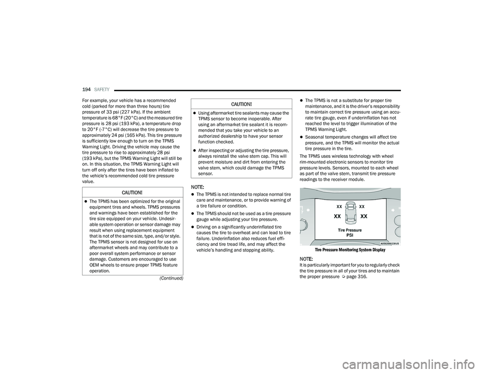
The TPMS uses wireless technology with wheel
rim-mounted electronic sensors to monitor tire
pressure levels. Sensors, mounted to each wheel
as part of the valve stem, transmit tire pressure
readings to the receiver module.
Tire Pressure Monitoring System Display
NOTE:It is particularly important for you to regularly check
the tire pressure in all of your tires and to maintain
the proper pressure Ú page 316.
CAUTION!
The TPMS has been optimized for the original
equipment tires and wheels. TPMS pressures
and warnings have been established for the
tire size equipped on your vehicle. Undesir -
able system operation or sensor damage may
result when using replacement equipment
that is not of the same size, type, and/or style.
The TPMS sensor is not designed for use on
aftermarket wheels and may contribute to a
poor overall system performance or sensor
damage. Customers are encouraged to use
OEM wheels to ensure proper TPMS feature
operation.
Using aftermarket tire sealants may cause the
TPMS sensor to become inoperable. After
using an aftermarket tire sealant it is recom -
mended that you take your vehicle to an
authorized dealership to have your sensor
function checked.
After inspecting or adjusting the tire pressure,
always reinstall the valve stem cap. This will
prevent moisture and dirt from entering the
valve stem, which could damage the TPMS
sensor.
CAUTION!
22_WD_OM_EN_USC_t.book Page 194
Page 197 of 332
SAFETY195
The TPMS consists of the following components:
Receiver module
Four TPMS sensors
Various TPMS messages, which display in the
instrument cluster, and a graphic displaying tire
pressures
TPMS Warning Light
Tire Pressure Monitoring System Low
Pressure Warnings
The TPMS Warning Light will illuminate in
the instrument cluster, and an audible
chime will be activated, when one or
more of the four active road tire
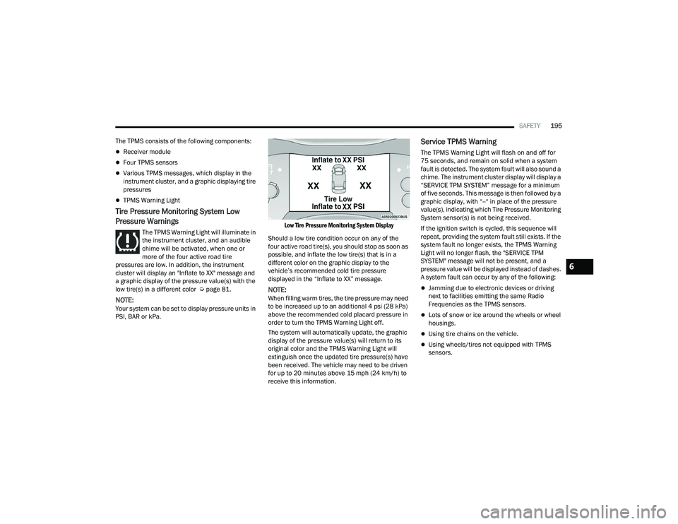
pressures are low. In addition, the instrument
cluster will display an "Inflate to XX" message and
a graphic display of the pressure value(s) with the
low tire(s) in a different color Ú page 81.
NOTE:Your system can be set to display pressure units in
PSI, BAR or kPa.
Low Tire Pressure Monitoring System Display
Should a low tire condition occur on any of the
four active road tire(s), you should stop as soon as
possible, and inflate the low tire(s) that is in a
different color on the graphic display to the
vehicle’s recommended cold tire pressure
displayed in the “Inflate to XX” message.
NOTE:When filling warm tires, the tire pressure may need
to be increased up to an additional 4 psi (28 kPa)
above the recommended cold placard pressure in
order to turn the TPMS Warning Light off.
The system will automatically update, the graphic
display of the pressure value(s) will return to its
original color and the TPMS Warning Light will
extinguish once the updated tire pressure(s) have
been received. The vehicle may need to be driven
for up to 20 minutes above 15 mph (24 km/h) to
receive this information.
Service TPMS Warning
The TPMS Warning Light will flash on and off for
75 seconds, and remain on solid when a system
fault is detected. The system fault will also sound a
chime. The instrument cluster display will display a
“SERVICE TPM SYSTEM” message for a minimum
of five seconds. This message is then followed by a
graphic display, with “--“ in place of the pressure
value(s), indicating which Tire Pressure Monitoring
System sensor(s) is not being received.
If the ignition switch is cycled, this sequence will
repeat, providing the system fault still exists. If the
system fault no longer exists, the TPMS Warning
Light will no longer flash, the "SERVICE TPM
SYSTEM" message will not be present, and a
pressure value will be displayed instead of dashes.
A system fault can occur by any of the following:
Jamming due to electronic devices or driving
next to facilities emitting the same Radio
Frequencies as the TPMS sensors.
Lots of snow or ice around the wheels or wheel
housings.
Using tire chains on the vehicle.
Using wheels/tires not equipped with TPMS
sensors.
6
22_WD_OM_EN_USC_t.book Page 195
Page 198 of 332
196SAFETY
NOTE:There is no TPMS sensor in the spare tire. The
TPMS will not be able to monitor the tire pressure.
If you install the spare tire in place of a road tire
that has a pressure below the low-pressure
warning limit, upon the next ignition switch cycle,
the TPMS Warning Light will remain on, a chime will
sound, and the instrument cluster display will still
display a pressure value in the different color
graphic display and an “Inflate to XX” message will
be displayed. After driving the vehicle for up to
20 minutes above 15 mph (24 km/h), the TPMS
Warning Light will flash on and off for 75 seconds
and then remain on solid. In addition, the
instrument cluster display will display a “SERVICE
TPM SYSTEM" message for five seconds and then
display dashes (--) in place of the pressure value.
For each subsequent ignition switch cycle, a chime
will sound, the TPMS Warning Light will flash on
and off for 75 seconds and then remain on solid,
and the instrument cluster display will display a
"SERVICE TPM SYSTEM" message for five seconds
and then display dashes (--) in place of the
pressure value. Once you repair or replace the
original road tire, and reinstall it on the vehicle in
place of the spare tire, the TPMS will update auto -
matically. In addition, the TPMS Warning Light will turn off
and the graphic in the instrument cluster display
will display a new pressure value instead of
dashes (--), as long as no tire pressure is below the
low-pressure warning limit in any of the four active
road tires. The vehicle may need to be driven for up
to 20 minutes above 15 mph (24 km/h) in order
for the TPMS to receive this information.
TPMS Deactivation — If Equipped
The TPMS can be deactivated if replacing all four
wheel and tire assemblies (road tires) with wheel
and tire assemblies that do not have TPMS
sensors, such as when installing winter wheel and
tire assemblies on your vehicle.
To deactivate the TPMS, first, replace all four wheel
and tire assemblies (road tires) with tires not
equipped with TPMS sensors. Then, drive the
vehicle for 20 minutes above 15 mph (24 km/h).
The TPMS will chime, the TPMS Warning Light will
flash on and off for 75 seconds and then remain
on. The instrument cluster will display the
“SERVICE TPM SYSTEM” message and then
display dashes (--) in place of the pressure values.
Beginning with the next ignition cycle, the TPMS
will no longer chime or display the “SERVICE TPM
SYSTEM” message in the instrument cluster but
dashes (--) will remain in place of the pressure
values.To reactivate the TPMS, replace all four wheel and
tire assemblies (road tires) with tires equipped with
TPMS sensors. Then, drive the vehicle for up to
20 minutes above 15 mph (24 km/h). The TPMS
will chime, the TPMS Warning Light will flash on
and off for 75 seconds and then turn off. The
instrument cluster will display the “SERVICE TPM
SYSTEM” message and then display pressure
values in place of the dashes. On the next ignition
cycle the "SERVICE TPM SYSTEM" message will no
longer be displayed as long as no system fault
exists.
OCCUPANT RESTRAINT SYSTEMS
Some of the most important safety features in your
vehicle are the restraint systems:
OCCUPANT RESTRAINT SYSTEMS
F
EATURES
Seat Belt Systems
Supplemental Restraint Systems (SRS) Air Bags
Child Restraints
Some of the safety features described in this
section may be standard equipment on some
models, or may be optional equipment on others.
If you are not sure, ask an authorized dealer.
22_WD_OM_EN_USC_t.book Page 196
Page 239 of 332
IN CASE OF EMERGENCY237
(Continued)
5. The SOS operator may attempt to contact
appropriate emergency responders and
provide them with important vehicle
information and GPS coordinates. SOS Call System Limitations
Vehicles sold in Mexico
DO NOT have SOS Call
system capabilities.
SOS or other emergency line operators in Mexico
may not answer or respond to SOS system calls.
If the SOS Call system detects a malfunction, any
of the following may occur at the time the
malfunction is detected, and at the beginning of
each ignition cycle:
The Rearview Mirror light located between the
SOS and ASSIST buttons will continuously illumi -
nate red.
The Device Screen will display the following
message “Vehicle device requires service.
Please contact an authorized dealer.”
An In-Vehicle Audio message will state “Vehicle
device requires service. Please contact an
authorized dealer.”
WARNING!
If anyone in the vehicle could be in danger
(e.g., fire or smoke is visible, dangerous road
conditions or location), do not wait for voice
contact from an Emergency Services Agent. All
occupants should exit the vehicle immediately
and move to a safe location.
Never place anything on or near the vehicle’s
operable network and GPS antennas. You
could prevent operable network and GPS
signal reception, which can prevent your
vehicle from placing an emergency call. An
operable network and GPS signal reception is
required for the SOS Call system to function
properly.
The SOS Call system is embedded into the
vehicle’s electrical system. Do not add after -
market electrical equipment to the vehicle’s
electrical system. This may prevent your
vehicle from sending a signal to initiate an
emergency call. To avoid interference that can
cause the SOS Call system to fail, never add
aftermarket equipment (e.g., two-way mobile
radio, CB radio, data recorder, etc.) to your
vehicle’s electrical system or modify the
antennas on your vehicle. IF YOUR VEHICLE
LOSES BATTERY POWER FOR ANY REASON
(INCLUDING DURING OR AFTER AN ACCI -
DENT), THE UCONNECT FEATURES, APPS AND
SERVICES, AMONG OTHERS, WILL NOT
OPERATE.
Modifications to any part of the SOS Call
system could cause the air bag system to fail
when you need it. You could be injured if the
air bag system is not there to help protect you.
WARNING!
7
22_WD_OM_EN_USC_t.book Page 237
Page 257 of 332
255
SERVICING AND MAINTENANCE
SCHEDULED SERVICING
Your vehicle is equipped with an automatic oil
change indicator system. The oil change indicator
system will remind you that it is time to take your
vehicle in for scheduled maintenance.
Based on engine operation conditions, the oil
change indicator message will illuminate. This
means that service is required for your vehicle.
Operating conditions such as frequent short-trips,
trailer tow, extremely hot or cold ambient
temperatures, and E85 fuel usage will influence
when the “Oil Change Required” message is
displayed. Have your vehicle serviced as soon as
possible, within the next 500 miles (805 km).An authorized dealer will reset the oil change
indicator message after completing the scheduled
oil change.
NOTE:Under no circumstances should oil change
intervals exceed 10,000 miles (16,000 km),
12 months or 350 hours of engine run time,
whichever comes first. The 350 hours of engine
run or idle time is generally only a concern for fleet
customers.
Once A Month Or Before A Long Trip:
Check engine oil level
Check windshield washer fluid level
Check the tire pressure and look for unusual
wear or damage
Check the fluid levels of the coolant reservoir,
brake master cylinder and fill as needed
Check function of all interior and exterior lights
8
22_WD_OM_EN_USC_t.book Page 255
Page 263 of 332
SERVICING AND MAINTENANCE261
(Continued)
CHECKING OIL LEVEL
To ensure proper engine lubrication, the engine oil
must be maintained at the correct level. Check the
oil level at regular intervals, such as every fuel
stop. The best time to check the engine oil level is
about five minutes after a fully warmed up engine
is shut off.
Checking the oil while the vehicle is on level ground
will improve the accuracy of the oil level readings.
There are four possible dipstick types:
Crosshatched zone.
Crosshatched zone marked SAFE.
Crosshatched zone marked with MIN at the low
end of the range and MAX at the high end of the
range.
Crosshatched zone marked with dimples at the
MIN and the MAX ends of the range.
NOTE:Always maintain the oil level within the crosshatch
markings on the dipstick.
Adding 1 quart (1.0 liter) of oil when the reading is
at the low end of the dipstick range will raise the oil
level to the high end of the range marking.
ADDING WASHER FLUID
The instrument cluster display will indicate when
the washer fluid level is low. When the sensor
detects a low fluid level, the Low Washer Fluid
Warning Light will illuminate and the "Washer Fluid
Low" message will display.
The fluid reservoir for the windshield washers and
the rear window washer is shared. The fluid
reservoir is located in the engine compartment, be
sure to check the fluid level at regular intervals. Fill
the reservoir with windshield washer solvent only
(not radiator antifreeze). When refilling the washer
fluid reservoir, take some washer fluid and apply it
to a cloth or towel and wipe clean the wiper blades,
this will help blade performance. To prevent
freeze-up of your windshield washer system in cold
weather, select a solution or mixture that meets or
exceeds the temperature range of your climate.
This rating information can be found on most
washer fluid containers.MAINTENANCE-FREE BATTERY
Your vehicle is equipped with a maintenance-free
battery. Water will never have to be added, and
periodic maintenance is not required.
CAUTION!
Overfilling or underfilling the crankcase will
cause aeration or loss of oil pressure. This could
damage your engine.
WARNING!
Commercially available windshield washer
solvents are flammable. They could ignite and
burn you. Care must be exercised when filling or
working around the washer solution.
WARNING!
Battery fluid is a corrosive acid solution and
can burn or even blind you. Do not allow
battery fluid to contact your eyes, skin, or
clothing. Do not lean over a battery when
attaching clamps Ú page 246. If acid
splashes in eyes or on skin, flush the area
immediately with large amounts of water.
Battery gas is flammable and explosive. Keep
flame or sparks away from the battery. Do not
use a booster battery or any other booster
source with an output greater than 12 Volts.
Do not allow cable clamps to touch each
other.
8
22_WD_OM_EN_USC_t.book Page 261