set clock DODGE DURANGO 2022 Owners Manual
[x] Cancel search | Manufacturer: DODGE, Model Year: 2022, Model line: DURANGO, Model: DODGE DURANGO 2022Pages: 332, PDF Size: 19.82 MB
Page 50 of 332
48GETTING TO KNOW YOUR VEHICLE
To turn off the headlights, rotate the headlight
switch back to the O (off) position.
NOTE:For vehicles sold in Canada, rotate the headlight
switch clockwise from the parking lights and
instrument panel lights position to the first detent
to turn on headlights, parking lights, and
instrument panel lights. Rotate the headlight
switch to the second detent for the AUTO position.
NOTE:
Your vehicle is equipped with plastic headlight
and fog light (if equipped) lenses that are lighter
and less susceptible to stone breakage than
glass lights. Plastic is not as scratch resistant as
glass and therefore different lens cleaning
procedures must be followed.
To minimize the possibility of scratching the
lenses and reducing light output, avoid wiping
with a dry cloth. To remove road dirt, wash with
a mild soap solution followed by rinsing.
DAYTIME RUNNING LIGHTS (DRLS)
The Daytime Running Lights (DRLs) come on
whenever the engine is running. The lights will
remain on until the ignition is placed in the OFF
position, or the parking brake is engaged. The
headlight switch must be used during normal
nighttime driving.
NOTE:
For vehicles sold in Canada, the Daytime
Running Lights will automatically deactivate
when the front fog lights are turned on.
If allowed by law in the country in which the
vehicle was purchased, the Daytime Running
Lights can be turned on and off using the
Uconnect system Ú page 156.
On some vehicles, the Daytime Running Lights
may deactivate or reduce intensity on one side
of the vehicle (when a turn signal is activated on
that side), or on both sides of the vehicle (when
the hazard warning lights are activated).
HIGH/LOW BEAM SWITCH
Push the multifunction lever toward the instrument
panel to switch the headlights to high beams. Pulling
the multifunction back will turn the low beams on.
AUTOMATIC HIGH BEAM — IF EQUIPPED
The Automatic High Beam Headlamp Control
system provides increased forward lighting at night
by automatically controlling the high beams
through the use of a camera mounted on the
inside rearview mirror. This camera detects vehicle
specific light and automatically switches from high
beams to low beams until the approaching vehicle
is out of view.
NOTE:
The Automatic High Beam Headlamp Control can
be turned on or off by selecting or deselecting
“Auto Dim High Beams” within your Uconnect
Settings
Ú
page 156, as well as turning the
headlight switch to the AUTO position.
Broken, muddy, or obstructed headlights and
taillights of vehicles in the field of view will
cause headlights to remain on longer (closer to
the vehicle). Also, dirt, film, and other obstruc -
tions on the windshield or camera lens will
cause the system to function improperly.
If the windshield or Automatic High Beam Head -
lamp Control mirror is replaced, the mirror must
be re-aimed to ensure proper performance.
See a local authorized dealer.CAUTION!
Do not use abrasive cleaning components,
solvents, steel wool or other abrasive materials
to clean the lenses.
22_WD_OM_EN_USC_t.book Page 48
Page 51 of 332
GETTING TO KNOW YOUR VEHICLE49
To opt out of the Advanced Auto High-Beam
Sensitivity Control (default) and enter Reduced
High-Beam Sensitivity Control (not recom -
mended), toggle high beam lever six full on/off
cycles within 10 seconds of ignition ON. System
will return to default setting upon ignition off.
FLASH-TO-PASS
You can signal another vehicle with your headlights
by lightly pulling the multifunction lever toward you.
This will cause the high beam headlights to turn on,
and remain on, until the lever is released.
AUTOMATIC HEADLIGHTS
This system automatically turns the headlights on
or off according to ambient light levels. To turn the
system on, rotate the headlight switch
counterclockwise to the AUTO position. When the
system is on, the headlight time delay feature is
also on. This means the headlights will stay on for
up to 90 seconds after you place the ignition into
the OFF position. The headlight time delay can be
programmed 0/30/60/90 seconds within
Uconnect Settings Ú page 156.
To turn the automatic system off, move the
headlight switch out of the AUTO position.
NOTE:The engine must be running before the headlights
will come on in the automatic mode.
PARKING LIGHTS AND PANEL LIGHTS
To turn on the parking lights and instrument panel
lights, rotate the headlight switch clockwise. To
turn off the parking lights, rotate the headlight
switch back to the O (off) position.
NOTE:Vehicles sold in Canada are equipped with a head -
light switch with an AUTO and ON detent but
without an OFF detent. Headlights will be deacti -
vated when the headlight switch is placed in the
parking lights position. However, the Daytime
Running Lights (DRLs) will be activated along with
the front and rear marker lights. The DRLs may be
deactivated when the parking brake is engaged.
AUTOMATIC HEADLIGHTS WITH WIPERS
If your vehicle is equipped with Automatic
Headlights, it also has this
customer-programmable feature. When your
headlights are in the automatic mode and the
engine is running, they will automatically turn on
when the wiper system is on. This feature is
programmable through the Uconnect system
Ú page 156.
NOTE:When your headlights come on during the daytime,
the vehicle will monitor outside brightness and
decide if the instrument panel needs to be dimmed
or not Ú page 51.
HEADLIGHT DELAY
To assist when exiting the vehicle, the headlight
delay feature will leave the headlights on for up to
90 seconds. This delay is initiated when the
ignition is placed in the OFF position while the
headlight switch is on, and then the headlight
switch is cycled off. Headlight delay can be
canceled by either turning the headlight switch on
then off, or by placing the ignition in the ON
position.
NOTE:The headlight delay time is programmable through
the Uconnect system Ú page 156.
LIGHTS-ON REMINDER
If the headlights, parking lights, or cargo lights are
left on after the ignition is placed in the OFF
position, the vehicle will chime when the driver’s
door is opened.
FOG LIGHTS — IF EQUIPPED
The fog lights are turned on by pushing fog light
button on the headlight switch.
2
22_WD_OM_EN_USC_t.book Page 49
Page 58 of 332
56GETTING TO KNOW YOUR VEHICLE
Driver And Passenger Temperature
Buttons
These buttons provide the driver and passenger
with independent temperature control.
Push the Up button on the faceplate or
press and slide the temperature bar
towards the red arrow button on
the touchscreen for warmer
temperature settings.
Push the Down button on the faceplate or
press and slide the temperature bar
towards the blue arrow button on
the touchscreen for cooler
temperature settings.
SYNC Button
Press the SYNC button on the
touchscreen to toggle the SYNC feature
on/off. The SYNC indicator illuminates
when SYNC is on. SYNC is used to
synchronize the front passenger temperature and rear passenger temperature, mode, and blower
settings with the driver temperature, mode, and
blower settings. Changing the front passenger
temperature or rear passenger temperature,
mode, and blower settings while in SYNC will
automatically exit this feature.
NOTE:The SYNC setting is only available on the touch
-
screen.
Blower Control
Blower Control is used to regulate the
amount of air forced through the Climate
Control system. There are seven blower
speeds available. Adjusting the blower
will cause automatic mode to switch to manual
operation. The speeds can be selected using either
the blower control knob on the faceplate or the
buttons on the touchscreen.
Faceplate: The blower speed increases as you
turn the blower control knob clockwise from the
lowest blower setting. The blower speed
decreases as you turn the blower control knob
counterclockwise.
Touchscreen: Use the small blower icon to
reduce the blower setting and the large blower
icon to increase the blower setting. Blower
speed can also be selected by pressing the
blower bar area between the icons.
Mode Control
Select Mode by pressing the Mode
button on the faceplate, or one of the
Mode buttons on the touchscreen to
change the airflow distribution mode.
The airflow distribution mode can be adjusted so
air comes from the instrument panel outlets, floor
outlets, defrost outlets and demist outlets.
Panel Mode
Air comes from the outlets in the
instrument panel. Each of these outlets
can be individually adjusted to direct the
flow of air. The air vanes of the center
outlets and outboard outlets can be moved up and
down or side to side to regulate airflow direction.
There is a shut-off wheel located below the air
vanes to shut off or adjust the amount of airflow
from these outlets.
Bi-Level Mode
Air comes from the instrument panel
outlets and floor outlets. A slight amount
of air is directed through the defrost and
side window demister outlets.
NOTE:Bi-Level mode is designed under comfort condi -
tions to provide cooler air out of the panel outlets
and warmer air from the floor outlets.
Do not use scrapers, sharp instruments, or
abrasive window cleaners on the interior
surface of the window.
Keep all objects a safe distance from the
window.
CAUTION!
22_WD_OM_EN_USC_t.book Page 56
Page 61 of 332
GETTING TO KNOW YOUR VEHICLE59
Rear Automatic Temperature Control
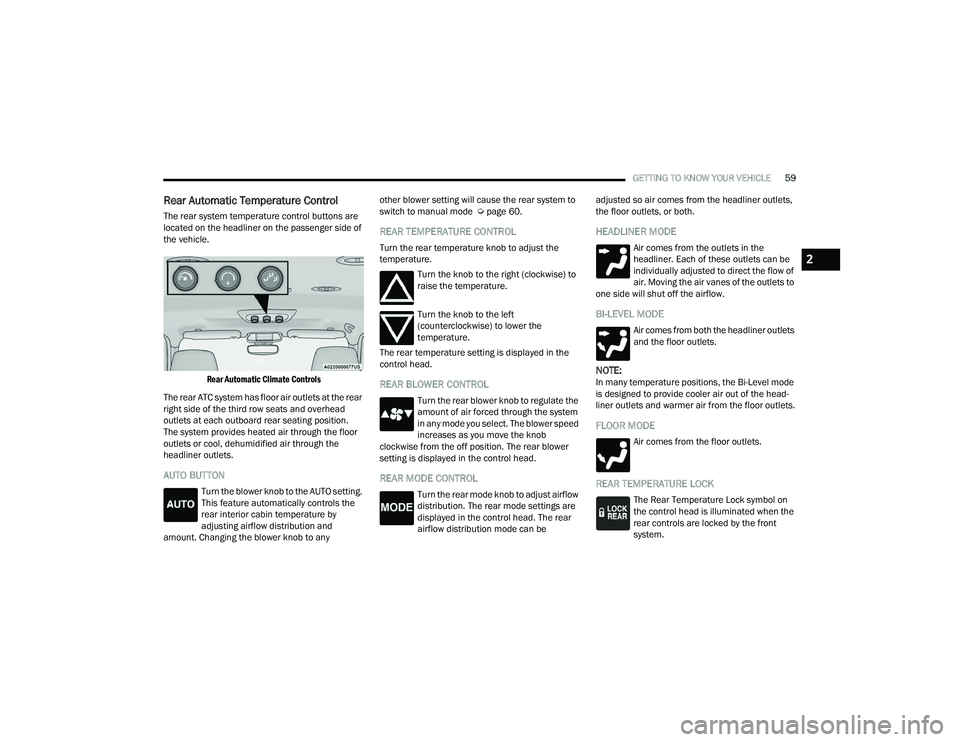
The rear system temperature control buttons are
located on the headliner on the passenger side of
the vehicle.
Rear Automatic Climate Controls
The rear ATC system has floor air outlets at the rear
right side of the third row seats and overhead
outlets at each outboard rear seating position.
The system provides heated air through the floor
outlets or cool, dehumidified air through the
headliner outlets.
AUTO BUTTON
Turn the blower knob to the AUTO setting.
This feature automatically controls the
rear interior cabin temperature by
adjusting airflow distribution and
amount. Changing the blower knob to any other blower setting will cause the rear system to
switch to manual mode Ú
page 60.
REAR TEMPERATURE CONTROL
Turn the rear temperature knob to adjust the
temperature.
Turn the knob to the right (clockwise) to
raise the temperature.
Turn the knob to the left
(counterclockwise) to lower the
temperature.
The rear temperature setting is displayed in the
control head.
REAR BLOWER CONTROL
Turn the rear blower knob to regulate the
amount of air forced through the system
in any mode you select. The blower speed
increases as you move the knob
clockwise from the off position. The rear blower
setting is displayed in the control head.
REAR MODE CONTROL
Turn the rear mode knob to adjust airflow
distribution. The rear mode settings are
displayed in the control head. The rear
airflow distribution mode can be adjusted so air comes from the headliner outlets,
the floor outlets, or both.
HEADLINER MODE
Air comes from the outlets in the
headliner. Each of these outlets can be
individually adjusted to direct the flow of
air. Moving the air vanes of the outlets to
one side will shut off the airflow.
BI-LEVEL MODE
Air comes from both the headliner outlets
and the floor outlets.
NOTE:In many temperature positions, the Bi-Level mode
is designed to provide cooler air out of the head -
liner outlets and warmer air from the floor outlets.
FLOOR MODE
Air comes from the floor outlets.
REAR TEMPERATURE LOCK
The Rear Temperature Lock symbol on
the control head is illuminated when the
rear controls are locked by the front
system.
2
22_WD_OM_EN_USC_t.book Page 59
Page 62 of 332
60GETTING TO KNOW YOUR VEHICLE
Rear Lock
Pressing the Rear Temperature Lock button on the
Uconnect touchscreen, illuminates a lock symbol
in the rear display. The rear temperature and air
source are controlled from the front Uconnect
system.
Rear second row occupants can only adjust the
rear ATC control when the Rear Temperature Lock
button is turned off.
The rear ATC is located in the headliner, near the
center of the vehicle.
Press the Rear Temperature Lock button on the
Uconnect touchscreen. This turns off the Rear
Temperature Lock icon in the rear temperature
knob.
Rotate the Rear Blower, Rear Temperature and
the Rear Mode Control knobs to suit your
comfort needs.
ATC is selected by adjusting the rear blower
knob counterclockwise to AUTO.
Once the desired temperature is displayed, the
ATC System will automatically achieve and
maintain that comfort level. When the system is
set up for your comfort level, it is not necessary to
change the settings. You will experience the
greatest efficiency by simply allowing the system to
function automatically.
AUTOMATIC TEMPERATURE CONTROL
(ATC)
Automatic Operation
1. Push the AUTO button on the front Automatic
Temperature Control (ATC) Panel and the
word “AUTO” will illuminate in the front ATC
display, along with two temperatures for the
driver and front passenger. The system will
then automatically regulate the amount of
airflow.
2. Adjust the temperature you would like the system to maintain, by adjusting the driver,
passenger, and rear temperatures. Once the
desired temperature is displayed, the system
will achieve and automatically maintain that
comfort level.
3. When the system is set up for your comfort level, it is not necessary to change the
settings. You will experience the greatest
efficiency by simply allowing the system to
function automatically.
NOTE:It is not necessary to move the temperature
settings. The system automatically adjusts the
temperature, mode and fan speed to provide
comfort as quickly as possible.
To provide you with maximum comfort in the
automatic mode, during cold start-ups, the blower fan will remain on low until the engine warms up.
The fan will engage immediately if the Defrost
mode is selected, or by changing the front blower
knob setting.
Manual Operation Override
This system offers a full complement of manual
override features. The AUTO symbol in the front
ATC display will be turned off when the system is
being used in the manual mode.
NOTE:The system will not automatically sense the
presence of fog, mist or ice on the windshield.
Defrost mode must be manually selected to clear
the windshield and side glass.
CLIMATE VOICE RECOGNITION
Adjust vehicle temperatures hands-free and keep
everyone comfortable while you keep moving
ahead.
Push the VR button on the steering wheel. After the
beep, say one of the following commands:
“
Set driver temperature to 70 degrees ”
“Set passenger temperature to 70 degrees ”
Did you know: Voice Command for Climate may
only be used to adjust the interior temperature of
your vehicle. Voice Command will not work to
adjust the heated seats or steering wheel if
equipped.
22_WD_OM_EN_USC_t.book Page 60
Page 167 of 332
MULTIMEDIA165
Units
Clock/Clock & Date
When the Units button is pressed on the touchscreen, the system displays the different measurement options. The selected unit of measurement will display
in the instrument cluster display and Navigation system (if equipped). The available settings are:
NOTE:Depending on the vehicle’s options, feature settings may vary.
Setting Name Description
USThis setting will change the unit of measurement on the display to US.
Metric This setting will change the unit of measurement on the display to Metric.
Custom This setting changes the “Speed” (MPH or km/h), “Distance” (mi or km),
“Fuel Consumption” (MPG [US], MPG [UK], L/100 km, or km/L), “Pressure”
(psi, kPa, or bar), and “Temperature” (°C or °F) units of measurement
independently.
When the Clock/Clock & Date button is pressed on the touchscreen, the system displays the different options related to the vehicle’s internal clock.
NOTE:Depending on the vehicle’s options, feature settings may vary.
Setting Name
Description
Sync Time With GPSThis setting will sync the time to the GPS receiver in the system. The system
will control the time via the GPS location.
Set Time Hours This setting will allow you to set the hours. Sync Time With GPS must be off
for this setting to be available. The “+” setting will increase the hours.
The “-” setting will decrease the hours.
5
22_WD_OM_EN_USC_t.book Page 165
Page 248 of 332
246IN CASE OF EMERGENCY
14. Lower the jack to the fully closed position. Return the tools to the proper positions in the
tool bag. Fold the flap on the tool bag under
the tools and roll the tools in the bag
underneath the others. Use the hook and loop
fasteners to secure the tool bag to the jack
with the lug wrench on the forward side of the
jack. Expand the jack on the bracket by turning
the thumb screw clockwise until it is tight to
prevent rattles.
15. Reinstall the plastic plug into the floor of the cargo area. Roll up and store the Jack, Tool Kit
and Tire Changing Instructions. Reinstall the
cover for the jack in the rear storage bin.
16. Have the aluminum road wheel and tire repaired as soon as possible and properly
secure the spare tire, jack and tool kit.
JUMP STARTING
If your vehicle has a discharged battery, it can be
jump started using a set of jumper cables and a
battery in another vehicle, or by using a portable
battery booster pack. Jump starting can be
dangerous if done improperly, so please follow the
procedures in this section carefully.
NOTE:When using a portable battery booster pack, follow
the manufacturer's operating instructions and
precautions.
PREPARATIONS FOR JUMP START
The battery in your vehicle is located under the
passenger's front seat. There are remote terminals
located under the hood to assist in jump starting.
Under Hood Jump Starting Location
NOTE:Be sure that the disconnected cable ends do not
touch each other, or either vehicle, before properly
connected for jump starting.
WARNING!
A loose tire or jack thrown forward in a collision
or hard stop, could endanger the occupants of
the vehicle. Always stow the jack parts and the
spare tire in the places provided.
WARNING!
Do not attempt jump starting if the battery is
frozen. It could rupture or explode and cause
personal injury.
CAUTION!
Do not use a portable battery booster pack or
any other booster source with a system voltage
greater than 12 Volts or damage to the battery,
starter motor, alternator or electrical system
may occur.Remote Positive (+) Post
(Covered With Protective Cap)
Remote Negative (-) Post
(Covered With Protective Cap)
22_WD_OM_EN_USC_t.book Page 246