stop start DODGE DURANGO 2022 Owners Manual
[x] Cancel search | Manufacturer: DODGE, Model Year: 2022, Model line: DURANGO, Model: DODGE DURANGO 2022Pages: 332, PDF Size: 19.82 MB
Page 6 of 332
4
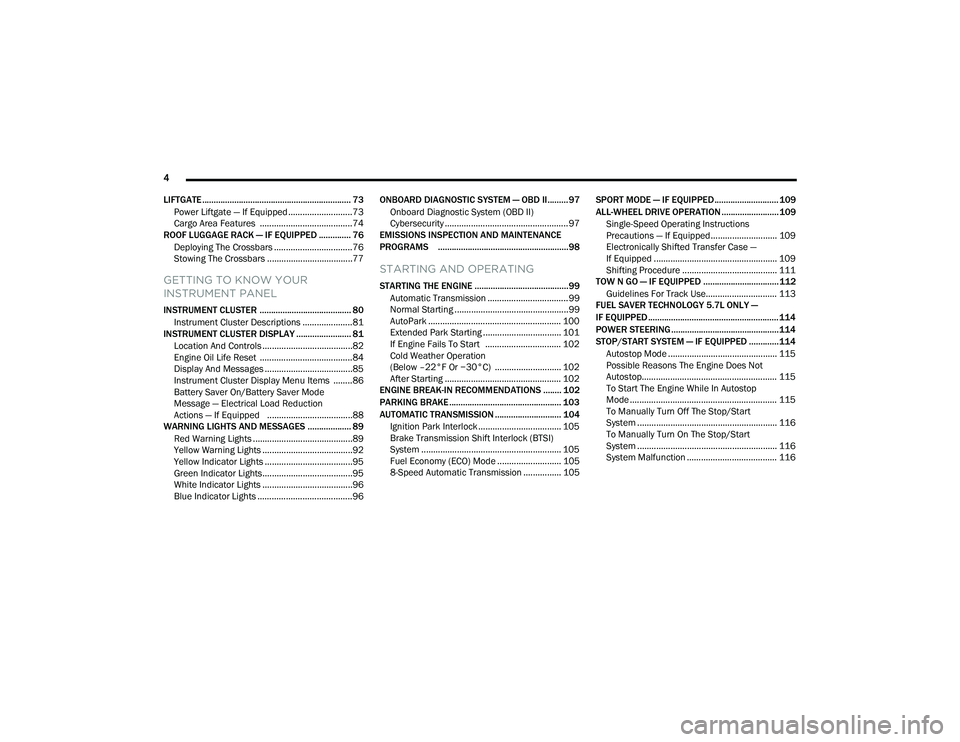
LIFTGATE ................................................................. 73 Power Liftgate — If Equipped ...........................73
Cargo Area Features .......................................74
ROOF LUGGAGE RACK — IF EQUIPPED .............. 76
Deploying The Crossbars .................................76
Stowing The Crossbars ....................................77
GETTING TO KNOW YOUR
INSTRUMENT PANEL
INSTRUMENT CLUSTER ........................................ 80Instrument Cluster Descriptions .....................81
INSTRUMENT CLUSTER DISPLAY ........................ 81
Location And Controls ......................................82
Engine Oil Life Reset .......................................84
Display And Messages .....................................85
Instrument Cluster Display Menu Items ........86
Battery Saver On/Battery Saver Mode
Message — Electrical Load Reduction
Actions — If Equipped ....................................88
WARNING LIGHTS AND MESSAGES ................... 89
Red Warning Lights ..........................................89
Yellow Warning Lights ......................................92
Yellow Indicator Lights .....................................95
Green Indicator Lights......................................95
White Indicator Lights ......................................96
Blue Indicator Lights ........................................96 ONBOARD DIAGNOSTIC SYSTEM — OBD II.........97
Onboard Diagnostic System (OBD II)
Cybersecurity ....................................................97
EMISSIONS INSPECTION AND MAINTENANCE
PROGRAMS .........................................................98
STARTING AND OPERATING
STARTING THE ENGINE .........................................99
Automatic Transmission ..................................99
Normal Starting ................................................99
AutoPark ........................................................ 100 Extended Park Starting ................................. 101
If Engine Fails To Start ................................ 102Cold Weather Operation
(Below –22°F Or −30°C) ............................ 102
After Starting ................................................. 102
ENGINE BREAK-IN RECOMMENDATIONS ........ 102
PARKING BRAKE ................................................. 103
AUTOMATIC TRANSMISSION ............................. 104
Ignition Park Interlock ................................... 105Brake Transmission Shift Interlock (BTSI)
System ........................................................... 105
Fuel Economy (ECO) Mode ........................... 1058-Speed Automatic Transmission ................ 105 SPORT MODE — IF EQUIPPED............................ 109
ALL-WHEEL DRIVE OPERATION ......................... 109
Single-Speed Operating Instructions
Precautions — If Equipped............................ 109
Electronically Shifted Transfer Case —
If Equipped .................................................... 109
Shifting Procedure ........................................ 111
TOW N GO — IF EQUIPPED ................................. 112
Guidelines For Track Use.............................. 113
FUEL SAVER TECHNOLOGY 5.7L ONLY —
IF EQUIPPED ......................................................... 114
POWER STEERING............................................... 114
STOP/START SYSTEM — IF EQUIPPED ............. 114 Autostop Mode .............................................. 115
Possible Reasons The Engine Does Not
Autostop......................................................... 115
To Start The Engine While In Autostop
Mode .............................................................. 115
To Manually Turn Off The Stop/Start
System ........................................................... 116
To Manually Turn On The Stop/Start
System ........................................................... 116
System Malfunction ...................................... 116
22_WD_OM_EN_USC_t.book Page 4
Page 13 of 332
11
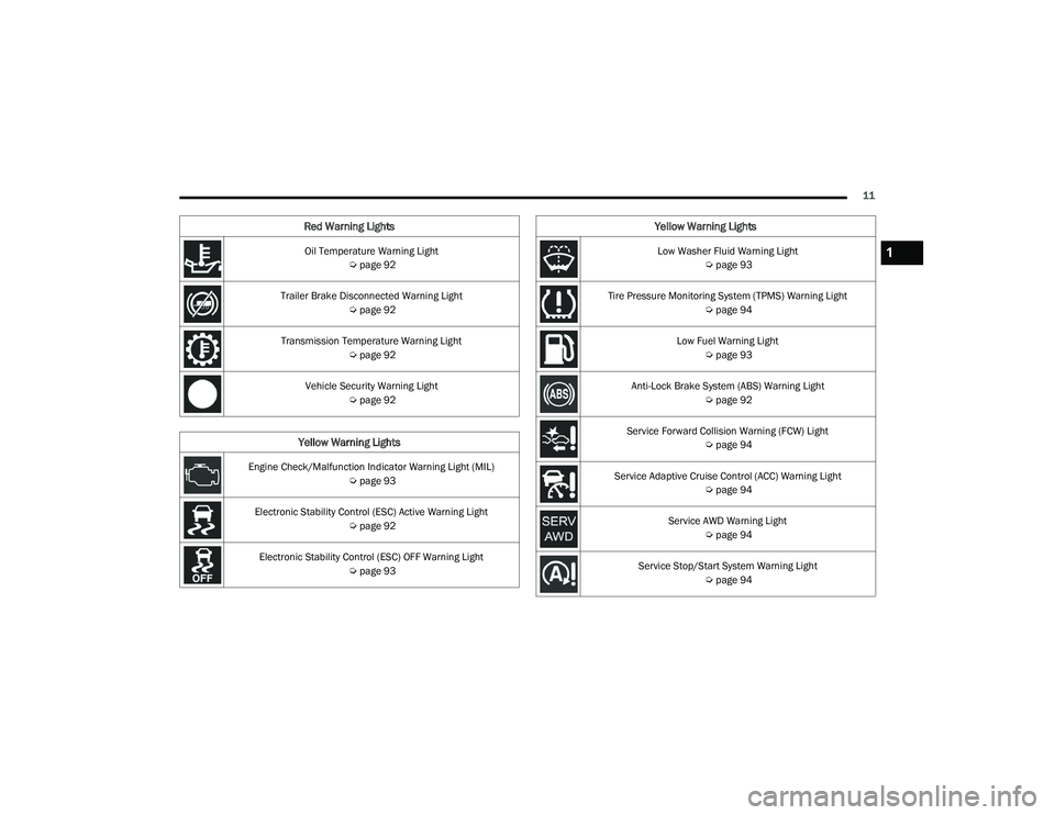
Oil Temperature Warning Light Úpage 92
Trailer Brake Disconnected Warning Light Úpage 92
Transmission Temperature Warning Light Úpage 92
Vehicle Security Warning Light Úpage 92
Yellow Warning Lights
Engine Check/Malfunction Indicator Warning Light (MIL)
Úpage 93
Electronic Stability Control (ESC) Active Warning Light Úpage 92
Electronic Stability Control (ESC) OFF Warning Light Úpage 93
Red Warning Lights
Low Washer Fluid Warning Light
Úpage 93
Tire Pressure Monitoring System (TPMS) Warning Light Úpage 94
Low Fuel Warning Light Úpage 93
Anti-Lock Brake System (ABS) Warning Light Úpage 92
Service Forward Collision Warning (FCW) Light Úpage 94
Service Adaptive Cruise Control (ACC) Warning Light Úpage 94
Service AWD Warning Light Úpage 94
Service Stop/Start System Warning Light Úpage 94
Yellow Warning Lights
1
22_WD_OM_EN_USC_t.book Page 11
Page 15 of 332
13
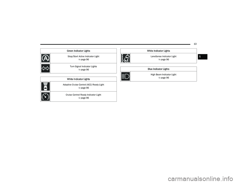
Stop/Start Active Indicator Light Úpage 96
Turn Signal Indicator Lights Úpage 96
White Indicator Lights
Adaptive Cruise Control (ACC) Ready Light
Úpage 96
Cruise Control Ready Indicator Light Úpage 96
Green Indicator Lights
LaneSense Indicator Light
Úpage 96
Blue Indicator Lights
High Beam Indicator Light
Úpage 96
White Indicator Lights
1
22_WD_OM_EN_USC_t.book Page 13
Page 18 of 332
16GETTING TO KNOW YOUR VEHICLE
(Continued)
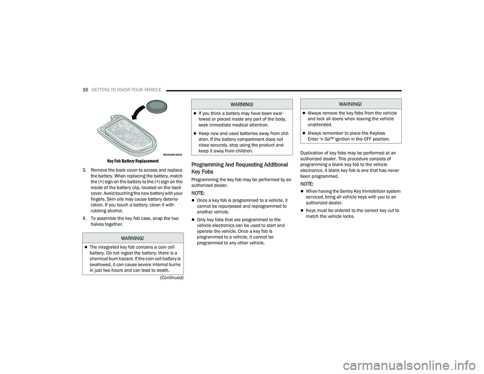
Key Fob Battery Replacement
3. Remove the back cover to access and replace the battery. When replacing the battery, match
the (+) sign on the battery to the (+) sign on the
inside of the battery clip, located on the back
cover. Avoid touching the new battery with your
fingers. Skin oils may cause battery deterio -
ration. If you touch a battery, clean it with
rubbing alcohol.
4. To assemble the key fob case, snap the two halves together.
Programming And Requesting Additional
Key Fobs
Programming the key fob may be performed by an
authorized dealer.
NOTE:
Once a key fob is programmed to a vehicle, it
cannot be repurposed and reprogrammed to
another vehicle.
Only key fobs that are programmed to the
vehicle electronics can be used to start and
operate the vehicle. Once a key fob is
programmed to a vehicle, it cannot be
programmed to any other vehicle. Duplication of key fobs may be performed at an
authorized dealer. This procedure consists of
programming a blank key fob to the vehicle
electronics. A blank key fob is one that has never
been programmed.
NOTE:
When having the Sentry Key Immobilizer system
serviced, bring all vehicle keys with you to an
authorized dealer.
Keys must be ordered to the correct key cut to
match the vehicle locks.
WARNING!
The integrated key fob contains a coin cell
battery. Do not ingest the battery; there is a
chemical burn hazard. If the coin cell battery is
swallowed, it can cause severe internal burns
in just two hours and can lead to death.
If you think a battery may have been swal-
lowed or placed inside any part of the body,
seek immediate medical attention.
Keep new and used batteries away from chil
-
dren. If the battery compartment does not
close securely, stop using the product and
keep it away from children.
WARNING!WARNING!
Always remove the key fobs from the vehicle
and lock all doors when leaving the vehicle
unattended.
Always remember to place the Keyless
Enter ‘n Go™ ignition in the OFF position.
22_WD_OM_EN_USC_t.book Page 16
Page 19 of 332
GETTING TO KNOW YOUR VEHICLE17
SENTRY KEY
The Sentry Key Immobilizer system prevents
unauthorized vehicle operation by disabling the
engine. The system does not need to be armed or
activated. Operation is automatic, regardless of
whether the vehicle is locked or unlocked.
The system uses a key fob, keyless push button
ignition and a Radio Frequency (RF) receiver to
prevent unauthorized vehicle operation. Therefore,
only key fobs that are programmed to the vehicle
can be used to start and operate the vehicle. The
system will shut the engine off in two seconds if an
incorrect key fob is used to start the engine.
After placing the ignition in the ON/RUN position,
the Vehicle Security Light will turn on for three
seconds for a bulb check. If the light remains on
after the bulb check, it indicates that there is a
problem with the electronics. In addition, if the light
begins to flash after the bulb check, it indicates
that someone used an invalid key fob to start the
engine. Either of these conditions will result in the
engine being shut off after two seconds.
If the Vehicle Security Light turns on during normal
vehicle operation (vehicle running for longer than
10 seconds), it indicates that there is a fault in the
electronics. Should this occur, have the vehicle
serviced as soon as possible by an authorized
dealer. All of the key fobs provided with your new vehicle
have been programmed to the vehicle electronics
Ú
page 316.
IGNITION SWITCH
KEYLESS ENTER ‘N GO™ IGNITION
This feature allows the driver to operate the
ignition switch with the push of a button as long as
the key fob is in the passenger compartment.
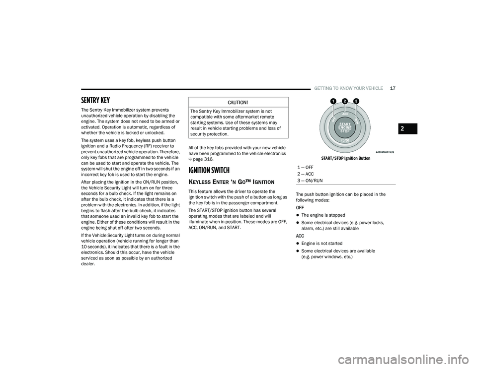
The START/STOP ignition button has several
operating modes that are labeled and will
illuminate when in position. These modes are OFF,
ACC, ON/RUN, and START.
START/STOP Ignition Button
The push button ignition can be placed in the
following modes:
OFF
The engine is stopped
Some electrical devices (e.g. power locks,
alarm, etc.) are still available
ACC
Engine is not started
Some electrical devices are available
(e.g. power windows, etc.)
CAUTION!
The Sentry Key Immobilizer system is not
compatible with some aftermarket remote
starting systems. Use of these systems may
result in vehicle starting problems and loss of
security protection.
1 — OFF
2 — ACC
3 — ON/RUN
2
22_WD_OM_EN_USC_t.book Page 17
Page 20 of 332
18GETTING TO KNOW YOUR VEHICLE
ON/RUN
Driving position
All electrical devices are available (e.g. climate
controls, etc.)
START
The engine will start (when foot is on the brake
pedal)
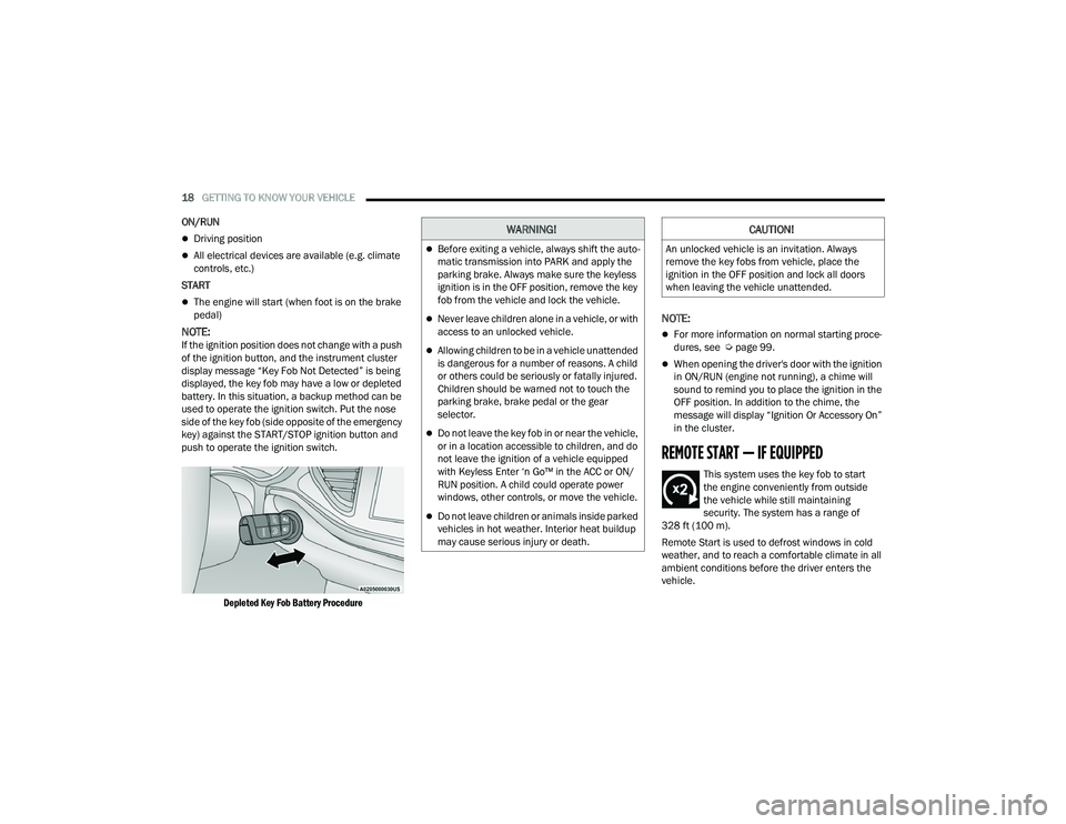
NOTE:If the ignition position does not change with a push
of the ignition button, and the instrument cluster
display message “Key Fob Not Detected” is being
displayed, the key fob may have a low or depleted
battery. In this situation, a backup method can be
used to operate the ignition switch. Put the nose
side of the key fob (side opposite of the emergency
key) against the START/STOP ignition button and
push to operate the ignition switch.
Depleted Key Fob Battery Procedure
NOTE:
For more information on normal starting proce -
dures, see Ú page 99.
When opening the driver's door with the ignition
in ON/RUN (engine not running), a chime will
sound to remind you to place the ignition in the
OFF position. In addition to the chime, the
message will display “Ignition Or Accessory On”
in the cluster.
REMOTE START — IF EQUIPPED
This system uses the key fob to start
the engine conveniently from outside
the vehicle while still maintaining
security. The system has a range of
328 ft (100 m).
Remote Start is used to defrost windows in cold
weather, and to reach a comfortable climate in all
ambient conditions before the driver enters the
vehicle.
WARNING!
Before exiting a vehicle, always shift the auto -
matic transmission into PARK and apply the
parking brake. Always make sure the keyless
ignition is in the OFF position, remove the key
fob from the vehicle and lock the vehicle.
Never leave children alone in a vehicle, or with
access to an unlocked vehicle.
Allowing children to be in a vehicle unattended
is dangerous for a number of reasons. A child
or others could be seriously or fatally injured.
Children should be warned not to touch the
parking brake, brake pedal or the gear
selector.
Do not leave the key fob in or near the vehicle,
or in a location accessible to children, and do
not leave the ignition of a vehicle equipped
with Keyless Enter ‘n Go™ in the ACC or ON/
RUN position. A child could operate power
windows, other controls, or move the vehicle.
Do not leave children or animals inside parked
vehicles in hot weather. Interior heat buildup
may cause serious injury or death.
CAUTION!
An unlocked vehicle is an invitation. Always
remove the key fobs from vehicle, place the
ignition in the OFF position and lock all doors
when leaving the vehicle unattended.
22_WD_OM_EN_USC_t.book Page 18
Page 22 of 332
20GETTING TO KNOW YOUR VEHICLE
Vehicle Security system (if equipped). Then, prior
to the end of the 15 minute cycle, push and
release the START/STOP ignition button.
The Remote Start system will turn the engine off if
the Remote Start button on the key fob is pushed
again, or if the engine is allowed to run for the
entire 15 minute cycle. Once the ignition is placed
in the ON/RUN position, the climate controls will
resume the previously set operations
(temperature, blower control, etc.).
NOTE:
To avoid unintentional shutdowns, the system
will disable for two seconds after receiving a
valid Remote Start request.
For vehicles equipped with the Keyless
Enter ‘n Go™ — Passive Entry feature, the
message “Remote Start Active — Push Start
Button” will display in the instrument cluster
display until you push the START/STOP ignition
button.
REMOTE START FRONT DEFROST
A
CTIVATION — IF EQUIPPED
When Remote Start is active, and the outside
ambient temperature is 40°F (4.5°C) or below, the
system will automatically activate front defrost for
15 minutes or less. The time is dependent on the
ambient temperature. Once the timer expires, the
system will automatically adjust the settings depending on ambient conditions. See “Remote
Start Comfort Systems — If Equipped” in the next
section for detailed operation.
REMOTE START COMFORT SYSTEMS —
I
F EQUIPPED
When Remote Start is activated, the front and rear
defrost will automatically turn on in cold weather.
The heated steering wheel and driver heated seat
feature will turn on if selected in the comfort menu
screen within Uconnect Settings Ú page 156. In
warm weather, the driver vented seat feature will
automatically turn on when Remote Start is
activated, if programmed in the comfort menu
screen. The vehicle will adjust the climate control
settings depending on the outside ambient
temperature.
Automatic Temperature Control (ATC) —
If Equipped
The climate controls will automatically adjust to
the optimal temperature and mode settings
depending on the outside ambient temperature.
This will occur until the ignition is placed in the
ON/RUN position, where the climate controls will
resume their previous settings.
Manual Temperature Control (MTC) — If Equipped
In ambient temperatures at 40°F (4.5°C) or
below, the climate settings will default to
maximum heat, with fresh air entering the cabin. If the front defrost timer expires, the
vehicle will enter Mix Mode.
In ambient temperatures from 40°F (4.5°C) to
78°F (26°C), the climate settings will be based
on the last settings selected by the driver.
In ambient temperatures at 78°F (26°C) or
above, the climate settings will default to
MAX A/C, Bi-Level Mode, and Recirculation on.
For more information on ATC, MTC, and climate
control settings, see Ú page 54.
NOTE:These features will stay on through the duration of
Remote Start until the ignition is placed in the
ON/RUN position. The climate control settings will
change if manually adjusted by the driver while the
vehicle is in Remote Start mode, and exit auto -
matic override. This includes the OFF button on the
climate controls, which will turn the system off.
REMOTE START WINDSHIELD WIPER
D
E–ICER ACTIVATION — IF EQUIPPED
When Remote Start is active and the outside
ambient temperature is less than 33°F (0.6°C),
the Windshield Wiper De-Icer will activate. Exiting
Remote Start will resume its previous operation.
If the Windshield Wiper De-Icer was active, the
timer and operation will continue.
22_WD_OM_EN_USC_t.book Page 20
Page 30 of 332
28GETTING TO KNOW YOUR VEHICLE
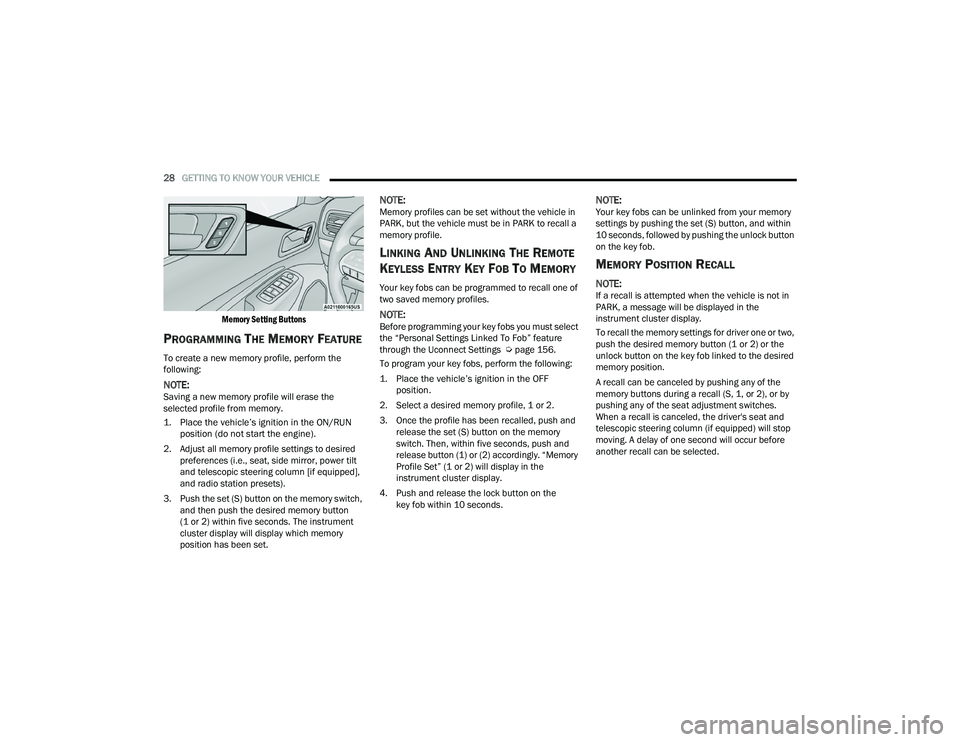
Memory Setting Buttons
PROGRAMMING THE MEMORY FEATURE
To create a new memory profile, perform the
following:
NOTE:Saving a new memory profile will erase the
selected profile from memory.
1. Place the vehicle’s ignition in the ON/RUN position (do not start the engine).
2. Adjust all memory profile settings to desired preferences (i.e., seat, side mirror, power tilt
and telescopic steering column [if equipped],
and radio station presets).
3. Push the set (S) button on the memory switch, and then push the desired memory button
(1 or 2) within five seconds. The instrument
cluster display will display which memory
position has been set.
NOTE:Memory profiles can be set without the vehicle in
PARK, but the vehicle must be in PARK to recall a
memory profile.
LINKING AND UNLINKING THE REMOTE
K
EYLESS ENTRY KEY FOB TO MEMORY
Your key fobs can be programmed to recall one of
two saved memory profiles.
NOTE:Before programming your key fobs you must select
the “Personal Settings Linked To Fob” feature
through the Uconnect Settings Ú page 156.
To program your key fobs, perform the following:
1. Place the vehicle’s ignition in the OFF position.
2. Select a desired memory profile, 1 or 2.
3. Once the profile has been recalled, push and release the set (S) button on the memory
switch. Then, within five seconds, push and
release button (1) or (2) accordingly. “Memory
Profile Set” (1 or 2) will display in the
instrument cluster display.
4. Push and release the lock button on the key fob within 10 seconds.
NOTE:Your key fobs can be unlinked from your memory
settings by pushing the set (S) button, and within
10 seconds, followed by pushing the unlock button
on the key fob.
MEMORY POSITION RECALL
NOTE:If a recall is attempted when the vehicle is not in
PARK, a message will be displayed in the
instrument cluster display.
To recall the memory settings for driver one or two,
push the desired memory button (1 or 2) or the
unlock button on the key fob linked to the desired
memory position.
A recall can be canceled by pushing any of the
memory buttons during a recall (S, 1, or 2), or by
pushing any of the seat adjustment switches.
When a recall is canceled, the driver's seat and
telescopic steering column (if equipped) will stop
moving. A delay of one second will occur before
another recall can be selected.
22_WD_OM_EN_USC_t.book Page 28
Page 38 of 332
36GETTING TO KNOW YOUR VEHICLE
Reclining The Seatback
The angle of the seatback can be adjusted forward
or rearward. Push the seatback switch forward or
rearward, the seat will move in the direction of the
switch. Release the switch when the desired
position is reached.
Power Lumbar — If Equipped
The power lumbar switch is located on the
outboard side of the power seat. Push the switch
forward to increase the lumbar support. Push the
switch rearward to decrease the lumbar support.
Pushing upward or downward on the switch will
raise and lower the position of the support.
HEATED SEATS — IF EQUIPPED
Front Heated Seats — If Equipped
The front heated seats control buttons
are located on the center stack below the
radio screen, or within the Uconnect
system.
Push the heated seat switch once to turn the HI
setting on.
Push the heated seat switch a second time to
turn the MED setting on.
Push the heated seat switch a third time to turn
the LO setting on.
Push the heated seat switch a fourth time to
turn the heating elements off.
NOTE:
Once a heat setting is selected, heat will be felt
within two to five minutes.
The engine must be running for the heated
seats to operate.
The level of heat selected will stay on until the
operator changes it.
For information on use with the Remote Start
system, see Ú page 20.
WARNING!
Adjusting a seat while driving may be
dangerous. Moving a seat while driving could
result in loss of control which could cause a
collision and serious injury or death.
Seats should be adjusted before fastening the
seat belts and while the vehicle is parked.
Serious injury or death could result from a
poorly adjusted seat belt.
Do not ride with the seatback reclined so that
the shoulder belt is no longer resting against
your chest. In a collision you could slide under
the seat belt, which could result in serious
injury or death.
CAUTION!
Do not place any article under a power seat or
impede its ability to move as it may cause
damage to the seat controls. Seat travel may
become limited if movement is stopped by an
obstruction in the seat's path.
WARNING!
Persons who are unable to feel pain to the
skin because of advanced age, chronic illness,
diabetes, spinal cord injury, medication,
alcohol use, exhaustion or other physical
condition must exercise care when using the
seat heater. It may cause burns even at low
temperatures, especially if used for long
periods of time.
Do not place anything on the seat or seatback
that insulates against heat, such as a blanket
or cushion. This may cause the seat heater to
overheat. Sitting in a seat that has been over -
heated could cause serious burns due to the
increased surface temperature of the seat.
22_WD_OM_EN_USC_t.book Page 36
Page 41 of 332
GETTING TO KNOW YOUR VEHICLE39
Head Restraint Removal — Rear Seats
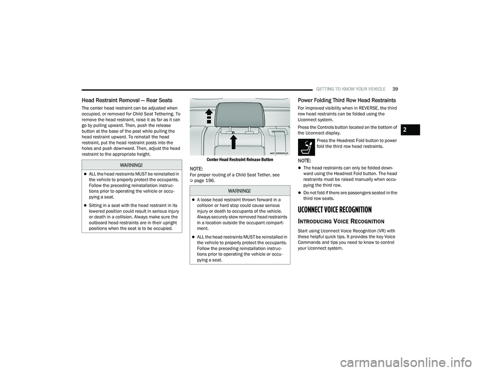
The center head restraint can be adjusted when
occupied, or removed for Child Seat Tethering. To
remove the head restraint, raise it as far as it can
go by pulling upward. Then, push the release
button at the base of the post while pulling the
head restraint upward. To reinstall the head
restraint, put the head restraint posts into the
holes and push downward. Then, adjust the head
restraint to the appropriate height.
Center Head Restraint Release Button
NOTE:For proper routing of a Child Seat Tether, see
Úpage 196.
Power Folding Third Row Head Restraints
For improved visibility when in REVERSE, the third
row head restraints can be folded using the
Uconnect system.
Press the Controls button located on the bottom of
the Uconnect display.
Press the Headrest Fold button to power
fold the third row head restraints.
NOTE:
The head restraints can only be folded down -
ward using the Headrest Fold button. The head
restraints must be raised manually when occu -
pying the third row.
Do not fold if there are passengers seated in the
third row seats.
UCONNECT VOICE RECOGNITION
INTRODUCING VOICE RECOGNITION
Start using Uconnect Voice Recognition (VR) with
these helpful quick tips. It provides the key Voice
Commands and tips you need to know to control
your Uconnect system.
WARNING!
ALL the head restraints MUST be reinstalled in
the vehicle to properly protect the occupants.
Follow the preceding reinstallation instruc -
tions prior to operating the vehicle or occu -
pying a seat.
Sitting in a seat with the head restraint in its
lowered position could result in serious injury
or death in a collision. Always make sure the
outboard head restraints are in their upright
positions when the seat is to be occupied.
WARNING!
A loose head restraint thrown forward in a
collision or hard stop could cause serious
injury or death to occupants of the vehicle.
Always securely stow removed head restraints
in a location outside the occupant compart -
ment.
ALL the head restraints MUST be reinstalled in
the vehicle to properly protect the occupants.
Follow the preceding reinstallation instruc -
tions prior to operating the vehicle or occu -
pying a seat.
2
22_WD_OM_EN_USC_t.book Page 39