stop start DODGE DURANGO 2022 Service Manual
[x] Cancel search | Manufacturer: DODGE, Model Year: 2022, Model line: DURANGO, Model: DODGE DURANGO 2022Pages: 332, PDF Size: 19.82 MB
Page 139 of 332
STARTING AND OPERATING137
vehicle is shifted into PARK, the vehicle’s ignition is
placed in the OFF position, or the touchscreen X
button to disable the display of the Rear View
Camera is pressed.
When enabled, active guidelines are overlaid on
the image to illustrate the width of the vehicle and
its projected backup path based on the steering
wheel position. A dashed center line overlay
indicates the center of the vehicle to assist with
parking or aligning to a hitch/receiver. Different
colored zones indicate the distance to the rear of
the vehicle.
The following table shows the approximate
distances for each zone:
NOTE:If snow, ice, mud, or any foreign substance builds
up on the camera lens, clean the lens, rinse with
water, and dry with a soft cloth. Do not cover the
lens.
Rear View Camera — Viewing At Speed When the vehicle is in PARK, NEUTRAL or
DRIVE, the Rear View Camera can be
activated with the Rear View Camera
button in the Controls tab of the Vehicle
Menu. This feature allows the customer to monitor
the area directly behind the vehicle (or trailer, if
equipped) for up to 10 seconds while driving. If the
vehicle speed remains below 8 mph (13 km/h),
the Rear View Camera image will be displayed
continuously until deactivated via the X button on
the touchscreen.
REFUELING THE VEHICLE
1. Open the fuel filler door by pushing on the outer edge of the fuel door.
NOTE:There is no fuel filler cap. Two flapper doors inside
the pipe seal the system.
2. Insert the fuel nozzle fully into the filler pipe – the nozzle opens and holds the flapper doors
while refueling.
Zone
Distance To The Rear Of
The Vehicle
Red 0 - 1 ft (0 - 30 cm)
Yellow 1 ft - 6.5 ft (30 cm - 2 m)
Green 6.5 ft or greater
(2 m or greater)
WARNING!
Drivers must be careful when backing up even
when using the ParkView Rear Back Up Camera.
Always check carefully behind your vehicle, and
be sure to check for pedestrians, animals, other
vehicles, obstructions, or blind spots before
backing up. You are responsible for the safety of
your surroundings and must continue to pay
attention while backing up. Failure to do so can
result in serious injury or death.
CAUTION!
To avoid vehicle damage, ParkView should
only be used as a parking aid. The ParkView
camera is unable to view every obstacle or
object in your drive path.
To avoid vehicle damage, the vehicle must be
driven slowly when using ParkView to be able
to stop in time when an obstacle is seen. It is
recommended that the driver look frequently
over his/her shoulder when using ParkView.
4
22_WD_OM_EN_USC_t.book Page 137
Page 147 of 332
STARTING AND OPERATING145
Towing Requirements — Tires
Do not attempt to tow a trailer while using a
compact spare tire.
Do not drive more than 50 mph (80 km/h) when
towing while using a full size spare tire.
Proper tire inflation pressures are essential to
the safe and satisfactory operation of your
vehicle.
Check the trailer tires for proper tire inflation
pressures before trailer usage.
Check for signs of tire wear or visible tire
damage before towing a trailer.
Replacing tires with a higher load carrying
capacity will not increase the vehicle's GVWR
and GAWR limits.
For further information Úpage 286.
Towing Requirements — Trailer Brakes
Do not interconnect the hydraulic brake system
or vacuum system of your vehicle with that of
the trailer. This could cause inadequate braking
and possible personal injury.
An electronically actuated trailer brake
controller is required when towing a trailer with
electronically actuated brakes. When towing a trailer equipped with a hydraulic surge actuated
brake system, an electronic brake controller is
not required.
Trailer brakes are recommended for trailers
over 1,000 lb (453 kg) and required for trailers
in excess of 2,000 lb (907 kg).
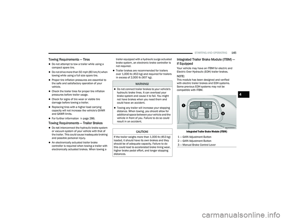
Integrated Trailer Brake Module (ITBM) —
If Equipped
Your vehicle may have an ITBM for electric and
Electric Over Hydraulic (EOH) trailer brakes.
NOTE:This module has been designed and verified
with electric trailer brakes and EOH systems.
Some previous EOH systems may not be
compatible with ITBM.
Integrated Trailer Brake Module (ITBM)
WARNING!
Do not connect trailer brakes to your vehicle's
hydraulic brake lines. It can overload your
brake system and cause it to fail. You might
not have brakes when you need them and
could have an accident.
Towing any trailer will increase your stopping
distance. When towing, you should allow for
additional space between your vehicle and the
vehicle in front of you. Failure to do so could
result in an accident.
CAUTION!
If the trailer weighs more than 1,000 lb (453 kg)
loaded, it should have its own brakes and they
should be of adequate capacity. Failure to do
this could lead to accelerated brake lining wear,
higher brake pedal effort, and longer stopping
distances.1 — GAIN Adjustment Button
2 — GAIN Adjustment Button
3 — Manual Brake Control Lever
4
22_WD_OM_EN_USC_t.book Page 145
Page 149 of 332
STARTING AND OPERATING147
Display Messages
The trailer brake control interacts with the
instrument cluster display. Display messages,
along with a single chime, will be displayed when a
malfunction is determined in the trailer
connection, trailer brake control, or on the trailer
Ú page 81.
NOTE:
An aftermarket controller may be available for
use with trailers with air or EOH trailer brake
systems. To determine the type of brakes on
your trailer and the availability of controllers,
check with your trailer manufacturer or dealer.
Removal of the ITBM will cause errors and it
may cause damage to the electrical system and
electronic modules of the vehicle. See an autho -
rized dealer if an aftermarket module is to be
installed.
Towing Requirements — Trailer Lights And
Wiring
Whenever pulling a trailer, regardless of the trailer
size, stoplights and turn signals on the trailer are
required for motoring safety.
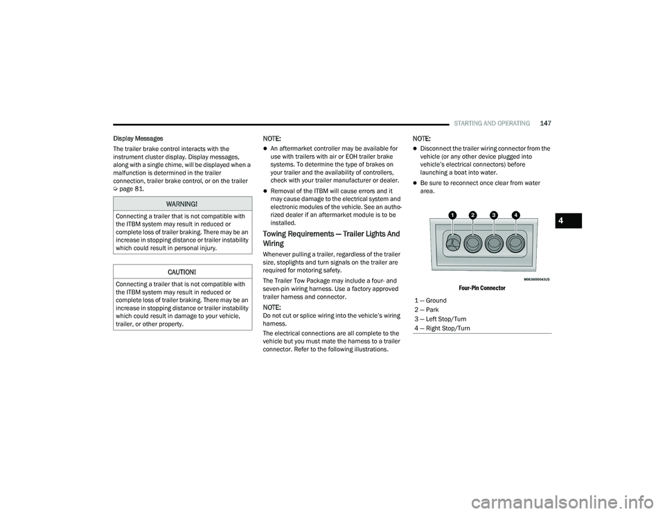
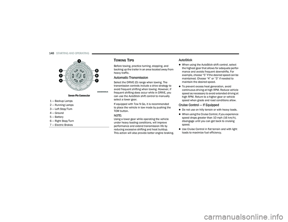
The Trailer Tow Package may include a four- and
seven-pin wiring harness. Use a factory approved
trailer harness and connector.
NOTE:Do not cut or splice wiring into the vehicle’s wiring
harness.
The electrical connections are all complete to the
vehicle but you must mate the harness to a trailer
connector. Refer to the following illustrations.
NOTE:
Disconnect the trailer wiring connector from the
vehicle (or any other device plugged into
vehicle’s electrical connectors) before
launching a boat into water.
Be sure to reconnect once clear from water
area.
Four-Pin Connector
WARNING!
Connecting a trailer that is not compatible with
the ITBM system may result in reduced or
complete loss of trailer braking. There may be an
increase in stopping distance or trailer instability
which could result in personal injury.
CAUTION!
Connecting a trailer that is not compatible with
the ITBM system may result in reduced or
complete loss of trailer braking. There may be an
increase in stopping distance or trailer instability
which could result in damage to your vehicle,
trailer, or other property.
1 — Ground
2 — Park
3 — Left Stop/Turn
4 — Right Stop/Turn
4
22_WD_OM_EN_USC_t.book Page 147
Page 150 of 332
148STARTING AND OPERATING
Seven-Pin Connector
TOWING TIPS
Before towing, practice turning, stopping, and
backing up the trailer in an area located away from
heavy traffic.
Automatic Transmission
Select the DRIVE (D) range when towing. The
transmission controls include a drive strategy to
avoid frequent shifting when towing. However, if
frequent shifting does occur while in DRIVE, you
can use the AutoStick shift control to manually
select a lower gear.
If equipped with Tow N Go, it is recommended
to place the vehicle in tow mode by pushing the
TOW button.
NOTE:Using a lower gear while operating the vehicle
under heavy loading conditions, will improve
performance and extend transmission life by
reducing excessive shifting and heat buildup.
This action will also provide better engine braking.
AutoStick
When using the AutoStick shift control, select
the highest gear that allows for adequate perfor -
mance and avoids frequent downshifts. For
example, choose “5” if the desired speed can be
maintained. Choose “4” or “3” if needed to
maintain the desired speed.
To prevent excess heat generation, avoid
continuous driving at high RPM. Reduce vehicle
speed as necessary to avoid extended driving at
high RPM. Return to a higher gear or vehicle
speed when grade and road conditions allow.
Cruise Control — If Equipped
Do not use on hilly terrain or with heavy loads.
When using the Cruise Control, if you experience
speed drops greater than 10 mph (16 km/h),
disengage until you can get back to cruising
speed.
Use Cruise Control in flat terrain and with light
loads to maximize fuel efficiency.
1 — Backup Lamps
2 — Running Lamps
3 — Left Stop/Turn
4 — Ground
5 — Battery
6 — Right Stop/Turn
7 — Electric Brakes
22_WD_OM_EN_USC_t.book Page 148
Page 153 of 332
STARTING AND OPERATING151
Shifting Into N (Neutral)
Use the following procedure to prepare your
vehicle for recreational towing.
1. Bring the vehicle to a complete stop on level
ground, with the engine running.
2. Press and hold the brake pedal.
3. Shift the transmission into NEUTRAL.
NOTE:
Steps 1 through 3 are requirements that
must be met before pushing the N (Neutral)
button, and must continue to be met until
the shift has been completed. If any of
these requirements are not met before
pushing the N (Neutral) button or are no
longer met during the shift, the N (Neutral)
indicator light will flash continuously until all
requirements are met or until the N
(Neutral) button is released.
The ignition must be in the ON/RUN mode
for a shift to take place and for the position
indicator lights to be operable. If the ignition
is not in the ON/RUN mode, the shift will not
take place and no position indicator lights
will be on or flashing.
A flashing N (Neutral) position indicator light
indicates that shift requirements have not
been met.
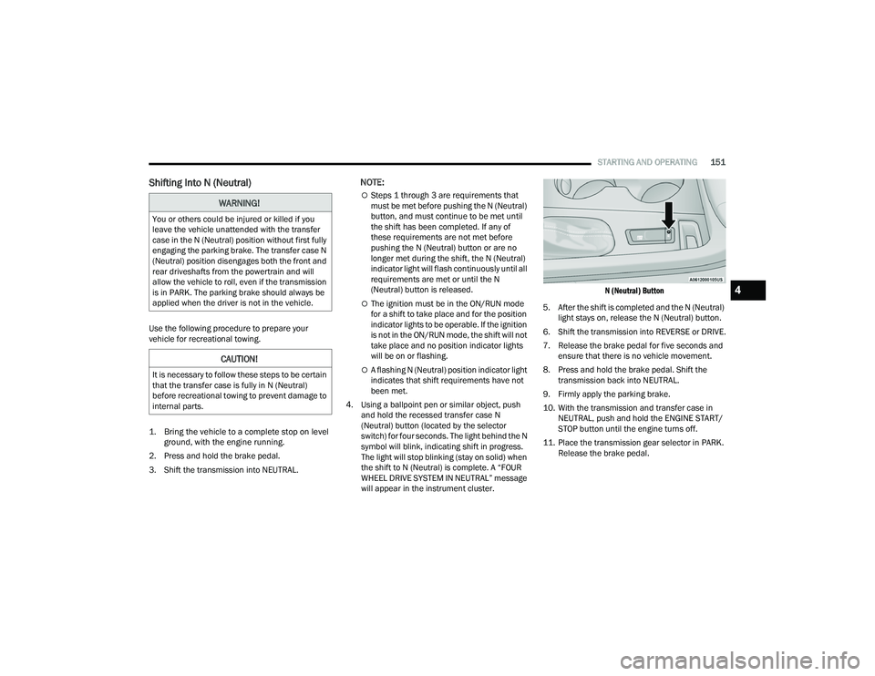
4. Using a ballpoint pen or similar object, push and hold the recessed transfer case N
(Neutral) button (located by the selector
switch) for four seconds. The light behind the N
symbol will blink, indicating shift in progress.
The light will stop blinking (stay on solid) when
the shift to N (Neutral) is complete. A “FOUR
WHEEL DRIVE SYSTEM IN NEUTRAL” message
will appear in the instrument cluster.
N (Neutral) Button
5. After the shift is completed and the N (Neutral) light stays on, release the N (Neutral) button.
6. Shift the transmission into REVERSE or DRIVE.
7. Release the brake pedal for five seconds and ensure that there is no vehicle movement.
8. Press and hold the brake pedal. Shift the transmission back into NEUTRAL.
9. Firmly apply the parking brake.
10. With the transmission and transfer case in NEUTRAL, push and hold the ENGINE START/
STOP button until the engine turns off.
11. Place the transmission gear selector in PARK. Release the brake pedal.
WARNING!
You or others could be injured or killed if you
leave the vehicle unattended with the transfer
case in the N (Neutral) position without first fully
engaging the parking brake. The transfer case N
(Neutral) position disengages both the front and
rear driveshafts from the powertrain and will
allow the vehicle to roll, even if the transmission
is in PARK. The parking brake should always be
applied when the driver is not in the vehicle.
CAUTION!
It is necessary to follow these steps to be certain
that the transfer case is fully in N (Neutral)
before recreational towing to prevent damage to
internal parts.
4
22_WD_OM_EN_USC_t.book Page 151
Page 154 of 332
152STARTING AND OPERATING
12. Push the ENGINE START/STOP button twice (without pressing the brake pedal) to turn the
ignition to the OFF mode.
13. Attach the vehicle to the tow vehicle using a suitable tow bar.
14. Release the parking brake.
Shifting Out Of N (Neutral)
Use the following procedure to prepare your
vehicle for normal usage.
1. Bring the vehicle to a complete stop, leaving it connected to the tow vehicle.
2. Firmly apply the parking brake.
3. Start the engine.
4. Press and hold the brake pedal.
5. Shift the transmission into NEUTRAL.
NOTE:
Steps 1 through 5 are requirements that
must be met before pushing the N (Neutral)
button, and must continue to be met until
the shift has been completed. If any of
these requirements are not met before
pushing the N (Neutral) button or are no
longer met during the shift, the N (Neutral)
indicator light will flash continuously until all
requirements are met or until the N
(Neutral) button is released.
The ignition must be in the ON/RUN mode
for a shift to take place and for the position
indicator lights to be operable. If the ignition
is not in the ON/RUN mode, the shift will not
take place and no position indicator lights
will be on or flashing.
A flashing N (Neutral) position indicator light
indicates that shift requirements have not
been met.
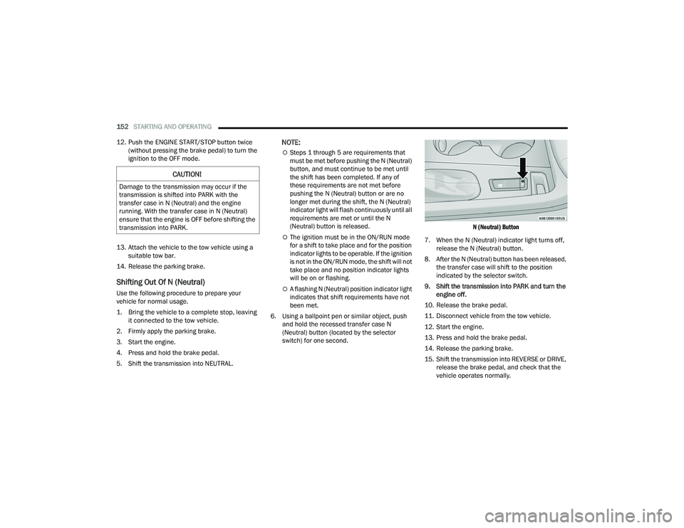
6. Using a ballpoint pen or similar object, push and hold the recessed transfer case N
(Neutral) button (located by the selector
switch) for one second.
N (Neutral) Button
7. When the N (Neutral) indicator light turns off, release the N (Neutral) button.
8. After the N (Neutral) button has been released, the transfer case will shift to the position
indicated by the selector switch.
9. Shift the transmission into PARK and turn the engine off.
10. Release the brake pedal.
11. Disconnect vehicle from the tow vehicle.
12. Start the engine.
13. Press and hold the brake pedal.
14. Release the parking brake.
15. Shift the transmission into REVERSE or DRIVE, release the brake pedal, and check that the
vehicle operates normally.
CAUTION!
Damage to the transmission may occur if the
transmission is shifted into PARK with the
transfer case in N (Neutral) and the engine
running. With the transfer case in N (Neutral)
ensure that the engine is OFF before shifting the
transmission into PARK.
22_WD_OM_EN_USC_t.book Page 152
Page 156 of 332
154STARTING AND OPERATING
Flowing Water
If the water is swift flowing and rising (as in storm
run-off), avoid crossing until the water level
recedes and/or the flow rate is reduced. If you
must cross flowing water avoid depths in excess of
9 inches (23 cm). The flowing water can erode the
streambed, causing your vehicle to sink into
deeper water. Determine exit point(s) that are
downstream of your entry point to allow for drifting.
Standing Water
Avoid driving in standing water deeper than
20 inches (51 cm), and reduce speed
appropriately to minimize wave effects. Maximum
speed in 20 inches (51 cm) of water is less than
5 mph (8 km/h).
Maintenance
After driving through deep water, inspect your
vehicle fluids and lubricants (engine oil,
transmission oil, axle, transfer case) to ensure the
fluids have not been contaminated. Contaminated
fluid (milky, foamy in appearance) should be
flushed/changed as soon as possible to prevent
component damage.
Driving In Snow, Mud And Sand
In heavy snow, when pulling a load, or for
additional control at slower speeds, shift the
transmission to a low gear and shift the transfer
case to AWD Low if necessary Ú page 109. Only
shift into a lower gear to maintain forward motion.
Over-revving the engine can spin the wheels and
traction will be lost.
Avoid abrupt downshifts on icy or slippery roads,
because engine braking may cause skidding and
loss of control.
Hill Climbing
NOTE:Before attempting to climb a hill, determine the
conditions at the crest and/or on the other side.
Before climbing a steep hill, shift the transmission
to a lower gear and shift the transfer case to AWD
Low. Use FIRST gear and AWD Low for very steep
hills.
If you stall or begin to lose forward motion while
climbing a steep hill, allow your vehicle to come to
a stop and immediately apply the brakes. Restart
the engine, and shift into REVERSE. Back slowly
down the hill, allowing the compression braking of
the engine to help regulate the speed. If the brakes
are required to control vehicle speed, apply them
lightly and avoid locking or skidding the tires. Remember, never drive diagonally across a hill;
always drive straight up or down.
If the wheels start to slip as you approach the crest
of a hill, ease off the accelerator and maintain
forward motion by turning the front wheels slowly.
This may provide a fresh “bite” into the surface and
will usually provide traction to complete the climb.
Traction Downhill
Shift the transmission into a low gear, and the
transfer case into AWD Low. Let the vehicle go
slowly down the hill with all four wheels turning
against engine compression drag. This will permit
you to control the vehicle speed and direction.
When descending mountains or hills, repeated
braking can cause brake fade with loss of braking
control. Avoid repeated heavy braking by
downshifting the transmission whenever possible.
WARNING!
If the engine stalls, you lose forward motion, or
cannot make it to the top of a steep hill or grade,
never attempt to turn around. To do so may
result in tipping and rolling the vehicle. Always
back carefully straight down a hill in REVERSE
gear. Never back down a hill in NEUTRAL using
only the brake.
22_WD_OM_EN_USC_t.book Page 154
Page 184 of 332
182 (Continued)
SAFETY
SAFETY FEATURES
ANTI-LOCK BRAKE SYSTEM (ABS)
The ABS provides increased vehicle stability and
brake performance under most braking conditions.
The system automatically prevents wheel lock and
enhances vehicle control during braking.
The ABS performs a self-check cycle to ensure that
the ABS is working properly each time the vehicle
is started and driven. During this self-check, you
may hear a slight clicking sound as well as some
related motor noises.
The ABS is activated during braking when the
system detects one or more wheels are beginning
to lock. Road conditions such as ice, snow, gravel,
bumps, railroad tracks, loose debris, or panic stops
may increase the likelihood of ABS activation(s).
You also may experience the following normal
characteristics when the ABS activates:
ABS motor noise or clicking sounds (you may
continue to hear for a short time after the stop).
Brake pedal pulsations.
A slight drop of the brake pedal at the end of the
stop.The ABS is designed to function with the Original
Equipment Manufacturer (OEM) tires. Modification
may result in degraded ABS performance.
Anti-Lock Brake System (ABS) Warning
Light
The yellow ABS Warning Light will turn on when the
ignition is placed in the ON/RUN mode and may
stay on for as long as four seconds.
If the ABS Warning Light remains on or comes on
while driving, it indicates that the anti-lock portion
of the brake system is not functioning and that
service is required. However, the conventional
brake system will continue to operate normally if
the ABS Warning Light is on.
WARNING!
The ABS contains sophisticated electronic
equipment that may be susceptible to interfer
-
ence caused by improperly installed or high
output radio transmitting equipment. This
interference can cause possible loss of
anti-lock braking capability. Installation of
such equipment should be performed by qual -
ified professionals.
Pumping of the Anti-Lock Brakes will diminish
their effectiveness and may lead to a collision.
Pumping makes the stopping distance longer.
Just press firmly on your brake pedal when you
need to slow down or stop.
The ABS cannot prevent the natural laws of
physics from acting on the vehicle, nor can it
increase braking or steering efficiency beyond
that afforded by the condition of the vehicle
brakes and tires or the traction afforded.
The ABS cannot prevent collisions, including
those resulting from excessive speed in turns,
following another vehicle too closely, or hydro -
planing.
The capabilities of an ABS equipped vehicle
must never be exploited in a reckless or
dangerous manner that could jeopardize the
user’s safety or the safety of others.
WARNING!
22_WD_OM_EN_USC_t.book Page 182
Page 185 of 332
SAFETY183
If the ABS Warning Light is on, the brake system
should be serviced as soon as possible to restore
the benefits of Anti-Lock Brakes. If the ABS
Warning Light does not come on when the ignition
is placed in the ON/RUN mode, have the light
repaired as soon as possible.
REAR SEAT REMINDER ALERT (RSRA)
RSRA will consider the presence of an object in the
rear seat when a rear entry/exit door is opened at
the beginning of each key cycle. To activate, the
rear door must be open for more than one second
and the vehicle must be placed in the ON/RUN
position within 10 minutes. When the potential
presence of an object is determined and/or
otherwise inferred, a message will appear in the
instrument cluster display reminding driver to
check the rear seat(s) immediately after key off
accompanied by an alert upon exiting the vehicle.
To enable or disable RSRA, see Ú page 156.
ELECTRONIC BRAKE CONTROL (EBC)
S
YSTEM
Your vehicle is equipped with an advanced
Electronic Brake Control (EBC) system. This system
includes Anti-Lock Brake System (ABS), Brake
Assist System (BAS), Electronic Brake Force
Distribution (EBD), Electronic Roll Mitigation
(ERM), Electronic Stability Control (ESC), Hill Start
Assist (HSA), and Traction Control System (TCS). These systems work together to enhance both
vehicle stability and control in various driving
conditions.
Your vehicle may also be equipped with Dynamic
Steering Torque (DST), Rain Brake Support (RBS),
Ready Alert Braking (RAB), and Trailer Sway
Control (TSC).
Brake Assist System (BAS)
The BAS is designed to optimize the vehicle’s
braking capability during emergency braking
maneuvers. The system detects an emergency
braking situation by sensing the rate and amount
of brake application and then applies optimum
pressure to the brakes. This can help reduce
braking distances. The BAS complements the
Anti-Lock Brake System (ABS). Applying the brakes
very quickly results in the best BAS assistance. To
receive the benefit of the system, you must apply
continuous braking pressure during the stopping
sequence (do not “pump” the brakes). Do not
reduce brake pedal pressure unless braking is no
longer desired. Once the brake pedal is released,
the BAS is deactivated.
Brake System Warning Light
The red Brake System Warning Light will turn on
when the ignition is placed in the ON/RUN mode
and may stay on for as long as four seconds.
If the Brake System Warning Light remains on or
comes on while driving, it indicates that the brake
system is not functioning properly and that
immediate service is required. If the Brake System
Warning Light does not come on when the ignition
is placed in the ON/RUN mode, have the light
repaired as soon as possible.
WARNING!
The Brake Assist System (BAS) cannot prevent
the natural laws of physics from acting on the
vehicle, nor can it increase the traction afforded
by prevailing road conditions. BAS cannot
prevent collisions, including those resulting from
excessive speed in turns, driving on very slippery
surfaces, or hydroplaning. The capabilities of a
BAS-equipped vehicle must never be exploited in
a reckless or dangerous manner, which could
jeopardize the user's safety or the safety of
others.
6
22_WD_OM_EN_USC_t.book Page 183
Page 188 of 332
186SAFETY
ESC Activation/Malfunction Indicator Light
And ESC OFF Indicator Light
The ESC Activation/Malfunction Indicator
Light in the instrument cluster will come
on when the ignition is placed in the ON/
RUN mode. It should go out with the
engine running. If the ESC Activation/Malfunction
Indicator Light comes on continuously with the
engine running, a malfunction has been detected
in the ESC system. If this light remains on after
several ignition cycles, and the vehicle has been
driven several miles (kilometers) at speeds greater
than 30 mph (48 km/h), see an authorized dealer
as soon as possible to have the problem
diagnosed and corrected.
The ESC Activation/Malfunction Indicator Light
starts to flash as soon as the tires lose traction and
the ESC system becomes active. The ESC
Activation/Malfunction Indicator Light also flashes
when TCS is active. If the ESC Activation/
Malfunction Indicator Light begins to flash during
acceleration, ease up on the accelerator and apply
as little throttle as possible. Be sure to adapt your
speed and driving to the prevailing road conditions.
The ESC OFF Indicator Light indicates
that the Electronic Stability Control (ESC)
is in a reduced mode.
NOTE:
The ESC Activation/Malfunction Indicator Light
and the ESC OFF Indicator Light come on
momentarily each time the ignition placed in the
ON position.
Each time the ignition is placed in the ON posi -
tion, the ESC system will be on even if it was
turned off previously.
The ESC system will make buzzing or clicking
sounds when it is active. This is normal; the
sounds will stop when ESC becomes inactive
following the maneuver that caused the ESC
activation.
Hill Start Assist (HSA)
HSA is designed to mitigate roll back from a
complete stop while on an incline. If the driver
releases the brake while stopped on an incline,
HSA will continue to hold the brake pressure for a
short period. If the driver does not apply the
throttle before this time expires, the system will
release brake pressure and the vehicle will roll
down the hill as normal.
The following conditions must be met in order for
HSA to activate:
The feature must be enabled.
The vehicle must be stopped.
The parking brake must be off.
The driver door must be closed.
The vehicle must be on a sufficient grade.
The gear selection must match vehicle uphill
direction (i.e., vehicle facing uphill is in forward
gear; vehicle backing uphill is in REVERSE gear).
HSA will work in REVERSE gear and all forward
gears. The system will not activate if the trans -
mission is in PARK or NEUTRAL. For vehicles
equipped with a manual transmission, if the
clutch is pressed, HSA will remain active.
WARNING!
There may be situations where the Hill Start
Assist (HSA) will not activate and slight rolling
may occur, such as on minor hills or with a
loaded vehicle, or while pulling a trailer. HSA is
not a substitute for active driving involvement.
It is always the driver’s responsibility to be
attentive to distance to other vehicles, people,
and objects, and most importantly brake
operation to ensure safe operation of the vehicle
under all road conditions. Your complete
attention is always required while driving to
maintain safe control of your vehicle. Failure to
follow these warnings can result in a collision or
serious personal injury.
22_WD_OM_EN_USC_t.book Page 186