warning DODGE DURANGO 2023 Owner's Guide
[x] Cancel search | Manufacturer: DODGE, Model Year: 2023, Model line: DURANGO, Model: DODGE DURANGO 2023Pages: 328, PDF Size: 13.82 MB
Page 47 of 328
GETTING TO KNOW YOUR VEHICLE45
SECURITY
It is advised to erase all channels before you sell or
turn in your vehicle.
To do this, push and hold the two outside buttons
for 20 seconds until the indicator flashes. Note
that all channels will be erased. Individual
channels cannot be erased.
The HomeLink® universal transmitter is disabled
when the Vehicle Security system is active.
TROUBLESHOOTING TIPS
If you are having trouble programming
HomeLink®, here are some of the most common
solutions:
Replace the battery in the garage door opener
hand-held transmitter.
Push the LEARN button on the garage door
opener to complete the training for a rolling
code.
Did you unplug the device for programming and
remember to plug it back in?
If you have any problems, or require assistance,
please call toll-free 1-800-355-3515 or on the
Internet at
HomeLink.com for information or
assistance.
EXTERIOR LIGHTS
MULTIFUNCTION LEVER
The multifunction lever is located on the left side of
the steering column.
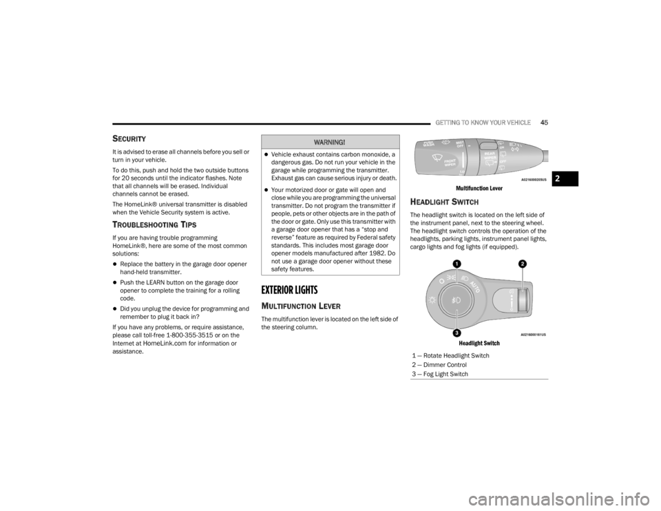
Multifunction Lever
HEADLIGHT SWITCH
The headlight switch is located on the left side of
the instrument panel, next to the steering wheel.
The headlight switch controls the operation of the
headlights, parking lights, instrument panel lights,
cargo lights and fog lights (if equipped).
Headlight Switch
WARNING!
Vehicle exhaust contains carbon monoxide, a
dangerous gas. Do not run your vehicle in the
garage while programming the transmitter.
Exhaust gas can cause serious injury or death.
Your motorized door or gate will open and
close while you are programming the universal
transmitter. Do not program the transmitter if
people, pets or other objects are in the path of
the door or gate. Only use this transmitter with
a garage door opener that has a “stop and
reverse” feature as required by Federal safety
standards. This includes most garage door
opener models manufactured after 1982. Do
not use a garage door opener without these
safety features.
1 — Rotate Headlight Switch
2 — Dimmer Control
3 — Fog Light Switch
2
23_WD_OM_EN_USC_t.book Page 45
Page 48 of 328
46GETTING TO KNOW YOUR VEHICLE
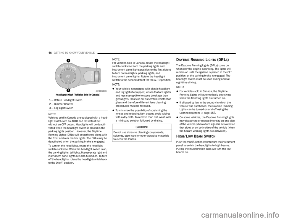
Headlight Switch (Vehicles Sold In Canada)
NOTE:Vehicles sold in Canada are equipped with a head -
light switch with an AUTO and ON detent but
without an OFF detent. Headlights will be deacti -
vated when the headlight switch is placed in the
parking lights position. However, the Daytime
Running Lights (DRLs) will be activated along with
the front and rear marker lights. The DRLs may be
deactivated when the parking brake is engaged.
To turn on the headlights, rotate the headlight
switch clockwise. When the headlight switch is on,
the parking lights, taillights, license plate light and
instrument panel lights are also turned on. To turn
off the headlights, rotate the headlight switch back
to the O (off) position.
NOTE:For vehicles sold in Canada, rotate the headlight
switch clockwise from the parking lights and
instrument panel lights position to the first detent
to turn on headlights, parking lights, and
instrument panel lights. Rotate the headlight
switch to the second detent for the AUTO position.
NOTE:
Your vehicle is equipped with plastic headlight
and fog light (if equipped) lenses that are lighter
and less susceptible to stone breakage than
glass lights. Plastic is not as scratch resistant as
glass and therefore different lens cleaning
procedures must be followed.
To minimize the possibility of scratching the
lenses and reducing light output, avoid wiping
with a dry cloth. To remove road dirt, wash with
a mild soap solution followed by rinsing.
DAYTIME RUNNING LIGHTS (DRLS)
The Daytime Running Lights (DRLs) come on
whenever the engine is running. The lights will
remain on until the ignition is placed in the OFF
position, or the parking brake is engaged. The
headlight switch must be used during normal
nighttime driving.
NOTE:
For vehicles sold in Canada, the Daytime
Running Lights will automatically deactivate
when the front fog lights are turned on.
If allowed by law in the country in which the
vehicle was purchased, the Daytime Running
Lights can be turned on and off using the
Uconnect system Ú page 153.
On some vehicles, the Daytime Running Lights
may deactivate or reduce intensity on one side
of the vehicle (when a turn signal is activated on
that side), or on both sides of the vehicle (when
the hazard warning lights are activated).
HIGH/LOW BEAM SWITCH
Push the multifunction lever toward the instrument
panel to switch the headlights to high beams.
Pulling the multifunction back will turn the low
beams on.
1 — Rotate Headlight Switch
2 — Dimmer Control
3 — Fog Light Switch
CAUTION!
Do not use abrasive cleaning components,
solvents, steel wool or other abrasive materials
to clean the lenses.
23_WD_OM_EN_USC_t.book Page 46
Page 54 of 328
52GETTING TO KNOW YOUR VEHICLE
Windshield Washers
To use the washer, push on the end of the lever
(toward the steering wheel) and hold. If the lever is
pushed while in the intermittent setting, the wipers
will turn on and operate for several cycles after the
end of the lever is released, and then resume the
intermittent interval previously selected.
If the end of the lever is pushed while the wipers
are in the off position, the wipers will operate for
several cycles, then turn off.
NOTE:As a protective measure, the washer will stop if the
switch is held for more than 20 seconds. Once the
switch is released the washer will resume normal
operation. Mist
Rotate the end of the lever downward to the MIST
position and release for a single wiping cycle.
NOTE:The Mist feature does not activate the washer
pump; therefore, no washer fluid will be sprayed on
the windshield. The washer function must be used
in order to spray the windshield with washer fluid.
For information on wiper care and replacement,
see Ú
page 261.
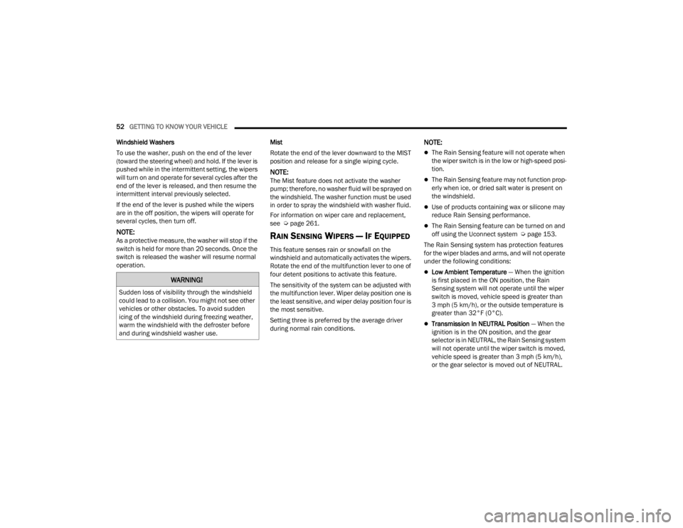
RAIN SENSING WIPERS — IF EQUIPPED
This feature senses rain or snowfall on the
windshield and automatically activates the wipers.
Rotate the end of the multifunction lever to one of
four detent positions to activate this feature.
The sensitivity of the system can be adjusted with
the multifunction lever. Wiper delay position one is
the least sensitive, and wiper delay position four is
the most sensitive.
Setting three is preferred by the average driver
during normal rain conditions.
NOTE:
The Rain Sensing feature will not operate when
the wiper switch is in the low or high-speed posi -
tion.
The Rain Sensing feature may not function prop -
erly when ice, or dried salt water is present on
the windshield.
Use of products containing wax or silicone may
reduce Rain Sensing performance.
The Rain Sensing feature can be turned on and
off using the Uconnect system Ú page 153.
The Rain Sensing system has protection features
for the wiper blades and arms, and will not operate
under the following conditions:
Low Ambient Temperature — When the ignition
is first placed in the ON position, the Rain
Sensing system will not operate until the wiper
switch is moved, vehicle speed is greater than
3 mph (5 km/h), or the outside temperature is
greater than 32°F (0°C).
Transmission In NEUTRAL Position — When the
ignition is in the ON position, and the gear
selector is in NEUTRAL, the Rain Sensing system
will not operate until the wiper switch is moved,
vehicle speed is greater than 3 mph (5 km/h),
or the gear selector is moved out of NEUTRAL.
WARNING!
Sudden loss of visibility through the windshield
could lead to a collision. You might not see other
vehicles or other obstacles. To avoid sudden
icing of the windshield during freezing weather,
warm the windshield with the defroster before
and during windshield washer use.
23_WD_OM_EN_USC_t.book Page 52
Page 69 of 328
GETTING TO KNOW YOUR VEHICLE67
(Continued)
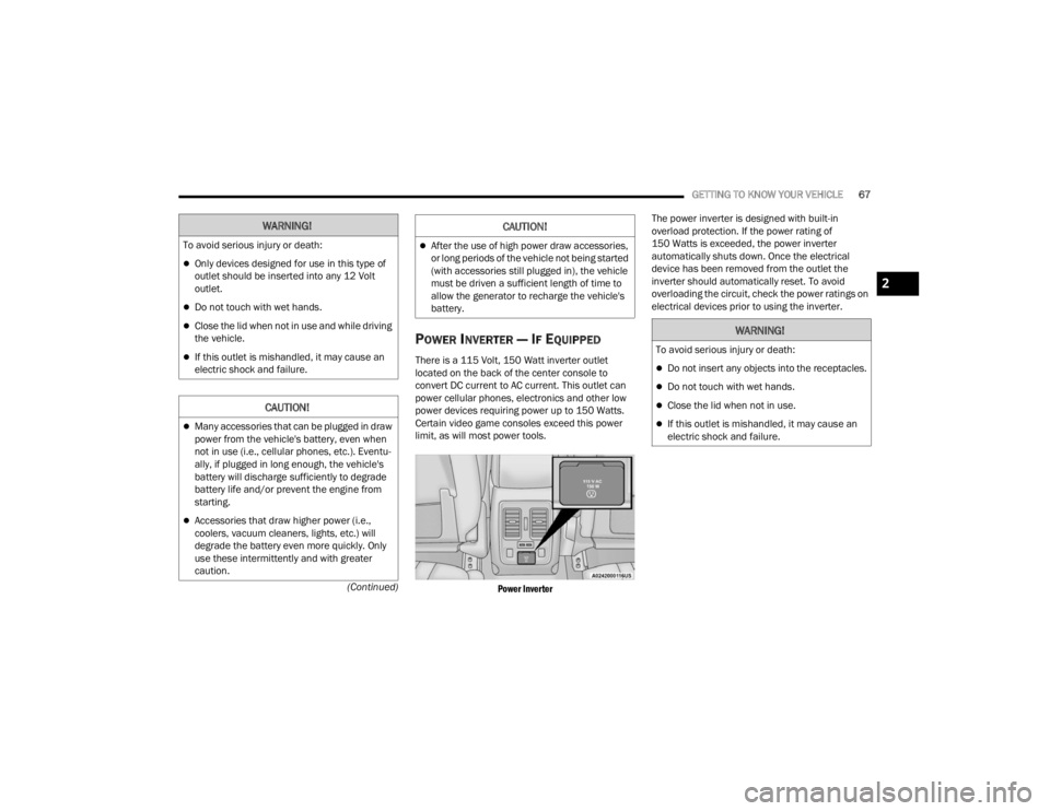
POWER INVERTER — IF EQUIPPED
There is a 115 Volt, 150 Watt inverter outlet
located on the back of the center console to
convert DC current to AC current. This outlet can
power cellular phones, electronics and other low
power devices requiring power up to 150 Watts.
Certain video game consoles exceed this power
limit, as will most power tools.
Power Inverter
The power inverter is designed with built-in
overload protection. If the power rating of
150 Watts is exceeded, the power inverter
automatically shuts down. Once the electrical
device has been removed from the outlet the
inverter should automatically reset. To avoid
overloading the circuit, check the power ratings on
electrical devices prior to using the inverter.
WARNING!
To avoid serious injury or death:
Only devices designed for use in this type of
outlet should be inserted into any 12 Volt
outlet.
Do not touch with wet hands.
Close the lid when not in use and while driving
the vehicle.
If this outlet is mishandled, it may cause an
electric shock and failure.
CAUTION!
Many accessories that can be plugged in draw
power from the vehicle's battery, even when
not in use (i.e., cellular phones, etc.). Eventu
-
ally, if plugged in long enough, the vehicle's
battery will discharge sufficiently to degrade
battery life and/or prevent the engine from
starting.
Accessories that draw higher power (i.e.,
coolers, vacuum cleaners, lights, etc.) will
degrade the battery even more quickly. Only
use these intermittently and with greater
caution.
After the use of high power draw accessories,
or long periods of the vehicle not being started
(with accessories still plugged in), the vehicle
must be driven a sufficient length of time to
allow the generator to recharge the vehicle's
battery.
CAUTION!
WARNING!
To avoid serious injury or death:
Do not insert any objects into the receptacles.
Do not touch with wet hands.
Close the lid when not in use.
If this outlet is mishandled, it may cause an
electric shock and failure.
2
23_WD_OM_EN_USC_t.book Page 67
Page 71 of 328
GETTING TO KNOW YOUR VEHICLE69
Automatic Window Features
Auto-Down Feature
Both the driver and front passenger window
switches have an Auto-Down feature. Push the
window switch past the first detent, release, and
the window will go down automatically.
To cancel the Auto-Down movement, operate the
switch in either the up or down direction and
release the switch.
Auto-Up Feature With Anti-Pinch Protection —
Driver And Front Passenger Door Only
Lift the window switch fully upward to the second
detent, release, and the window will go up
automatically. To stop the window from going all the way up
during the Auto-Up operation, push down on the
switch briefly.
If the window runs into any obstacle during
Auto-Up, it will reverse direction and then go back
down. Remove the obstacle and use the window
switch again to close the window.
NOTE:Any impact due to rough road conditions may
trigger the auto reverse function unexpectedly
during Auto-Up. If this happens, pull the switch
lightly to the first detent and hold it to close the
window manually.
Reset Auto-Up
Should the Auto-Up feature stop working, the
window may need to be reset. To reset Auto-Up:
1. Make sure the door is fully closed.
2. Pull the window switch up to close the window
completely and continue to hold the switch up
for an additional two seconds after the window
is closed. 3. Push the window switch down firmly to the
second detent to open the window completely
and continue to hold the switch down for an
additional two seconds after the window is
fully open.
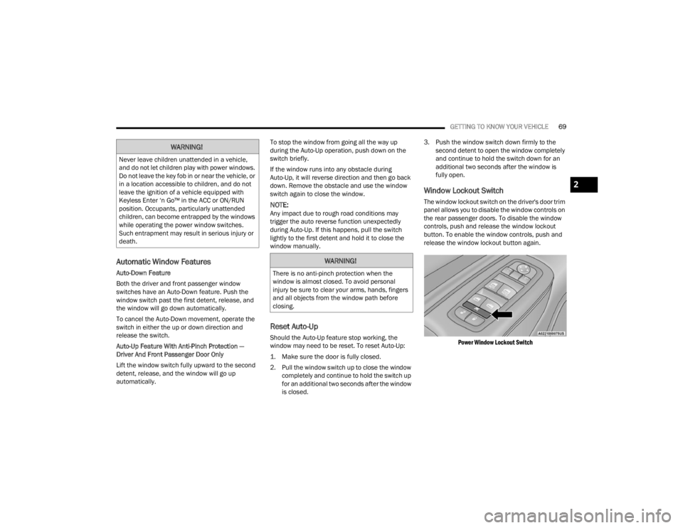
Window Lockout Switch
The window lockout switch on the driver's door trim
panel allows you to disable the window controls on
the rear passenger doors. To disable the window
controls, push and release the window lockout
button. To enable the window controls, push and
release the window lockout button again.
Power Window Lockout Switch
WARNING!
Never leave children unattended in a vehicle,
and do not let children play with power windows.
Do not leave the key fob in or near the vehicle, or
in a location accessible to children, and do not
leave the ignition of a vehicle equipped with
Keyless Enter ‘n Go™ in the ACC or ON/RUN
position. Occupants, particularly unattended
children, can become entrapped by the windows
while operating the power window switches.
Such entrapment may result in serious injury or
death.
WARNING!
There is no anti-pinch protection when the
window is almost closed. To avoid personal
injury be sure to clear your arms, hands, fingers
and all objects from the window path before
closing.
2
23_WD_OM_EN_USC_t.book Page 69
Page 72 of 328
70GETTING TO KNOW YOUR VEHICLE
WIND BUFFETING
Wind buffeting can be described as the perception
of pressure on the ears or a helicopter-type sound
in the ears. Your vehicle may exhibit wind buffeting
with the windows down, or the sunroof (if
equipped) in certain open or partially open
positions. This is a normal occurrence and can be
minimized. If the buffeting occurs with the rear
windows open, open the front and rear windows
together to minimize the buffeting. If the buffeting
occurs with the sunroof open, adjust the sunroof
opening to minimize the buffeting or open any
window.
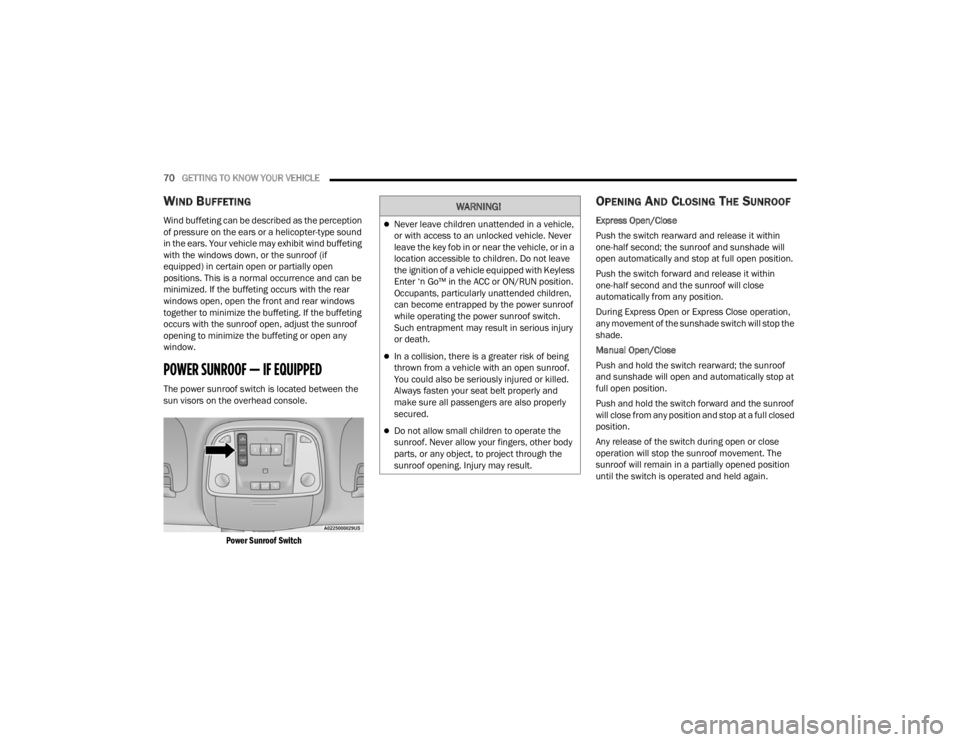
POWER SUNROOF — IF EQUIPPED
The power sunroof switch is located between the
sun visors on the overhead console.
Power Sunroof Switch
OPENING AND CLOSING THE SUNROOF
Express Open/Close
Push the switch rearward and release it within
one-half second; the sunroof and sunshade will
open automatically and stop at full open position.
Push the switch forward and release it within
one-half second and the sunroof will close
automatically from any position.
During Express Open or Express Close operation,
any movement of the sunshade switch will stop the
shade.
Manual Open/Close
Push and hold the switch rearward; the sunroof
and sunshade will open and automatically stop at
full open position.
Push and hold the switch forward and the sunroof
will close from any position and stop at a full closed
position.
Any release of the switch during open or close
operation will stop the sunroof movement. The
sunroof will remain in a partially opened position
until the switch is operated and held again.
WARNING!
Never leave children unattended in a vehicle,
or with access to an unlocked vehicle. Never
leave the key fob in or near the vehicle, or in a
location accessible to children. Do not leave
the ignition of a vehicle equipped with Keyless
Enter ‘n Go™ in the ACC or ON/RUN position.
Occupants, particularly unattended children,
can become entrapped by the power sunroof
while operating the power sunroof switch.
Such entrapment may result in serious injury
or death.
In a collision, there is a greater risk of being
thrown from a vehicle with an open sunroof.
You could also be seriously injured or killed.
Always fasten your seat belt properly and
make sure all passengers are also properly
secured.
Do not allow small children to operate the
sunroof. Never allow your fingers, other body
parts, or any object, to project through the
sunroof opening. Injury may result.
23_WD_OM_EN_USC_t.book Page 70
Page 73 of 328
GETTING TO KNOW YOUR VEHICLE71
Venting The Sunroof
Push and release the Vent button within one-half
second and the sunroof will open to the vent
position. This is called Express Vent, and it will
occur regardless of sunroof position. During
Express Vent operation, any movement of the
switch will stop the sunroof.
SUNSHADE OPERATION
The sunshade can be opened manually. However,
the sunshade will open automatically as the
sunroof opens.
NOTE:The sunshade cannot be closed if the sunroof is
open.
PINCH PROTECT FEATURE
This feature will detect an obstruction in the
closing of the sunroof during the Express Close
operation. If an obstruction in the path of the
sunroof is detected, the sunroof will automatically
retract. Remove the obstruction if this occurs.
NOTE:If three consecutive sunroof close attempts result
in Pinch Protect reversals, Pinch Protect will
disable and the sunroof must be closed in Manual
Mode.
SUNROOF MAINTENANCE
Use only a non-abrasive cleaner and a soft cloth to
clean the glass panel. Periodically check for and
clear out any debris that may have collected in the
tracks.
IGNITION OFF OPERATION
The power sunroof switch can remain active in
Accessory Delay for up to approximately
10 minutes after the vehicle’s ignition is placed
to the OFF position. Opening either front door
will cancel this feature.
This feature is programmable using the
Uconnect system Ú page 153.
HOOD
OPENING THE HOOD
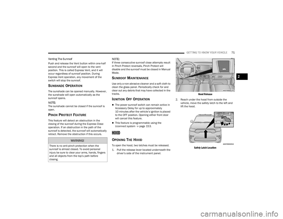
To open the hood, two latches must be released.
1. Pull the release lever located underneath the
driver’s side of the instrument panel.
Hood Release
2. Reach under the hood from outside the vehicle, move the safety latch to the left and
lift the hood.
Safety Latch Location
WARNING!
There is no anti-pinch protection when the
sunroof is almost closed. To avoid personal
injury be sure to clear your arms, hands, fingers
and all objects from the top’s path before
closing.
2
23_WD_OM_EN_USC_t.book Page 71
Page 74 of 328
72GETTING TO KNOW YOUR VEHICLE
NOTE:
Vehicle must be at a stop and the gear selector
must be in PARK.
While lifting the hood, use both hands.
Before lifting the hood, check that the wiper
arms are not in motion and not in the lifted posi -
tion.
CLOSING THE HOOD
In one continuous motion, pull down on the front
edge of the hood with moderate force until the
angle is below the crossover point (where the gas
props are no longer resisting) and let the hood
continue to fall closed from its own inertia.
LIFTGATE
POWER LIFTGATE — IF EQUIPPED
The power liftgate may be opened by
pushing the liftgate release handle
Ú page 22 or by pushing the liftgate
button on the key fob. Push the liftgate
button on the key fob twice within five seconds to
open or close the power liftgate.
NOTE:
When using the liftgate button on the key fob to
open the liftgate while the vehicle is locked, only
the liftgate will unlock leaving the other doors to
remain locked. Closing the liftgate will not relock
the liftgate. The lock button on the key fob, or
the Passive Entry lock button must be pushed to
relock.
If the electronic liftgate handle is used to open
the liftgate and all the doors unlock, the liftgate
and vehicle doors must be locked again. Use the
key fob, Passive Entry lock button, or the power
door lock switches on the front door panels.
The power liftgate may also be opened or closed by
pushing the liftgate button located on the front
overhead console. If the liftgate is fully open, it can
be closed by pushing the liftgate button located on
the left rear trim panel. If the liftgate is in motion,
pushing the button again will reverse the liftgate. When the liftgate button on the key fob is pushed
two times, the turn signals will flash to signal that
the liftgate is opening or closing (if Flash Lamps
with Lock is enabled in the Uconnect settings), and
the liftgate chime will be audible. The chime can be
turned on or off through the Uconnect Settings
Ú
page 153.
NOTE:
In the event of a power malfunction to the lift -
gate, an emergency liftgate latch release can be
used to open the liftgate. The emergency liftgate
latch release can be accessed through a snap-in
cover located on the liftgate trim panel.
If liftgate is left open for an extended period of
time, the liftgate may need to be closed manu -
ally to reset power liftgate functionality.
NOTE:
The power liftgate buttons will not operate if the
vehicle is in gear or the vehicle speed is above
0 mph (0 km/h).
WARNING!
Be sure the hood is fully latched before driving
your vehicle. If the hood is not fully latched, it
could open when the vehicle is in motion and
block your vision. Failure to follow this warning
could result in serious injury or death.WARNING!
During power operation, personal injury or cargo
damage may occur. Ensure the liftgate travel
path is clear. Make sure the liftgate is closed
and latched before driving away.
23_WD_OM_EN_USC_t.book Page 72
Page 75 of 328
GETTING TO KNOW YOUR VEHICLE73
(Continued)
The power liftgate will not operate in tempera -
tures below −22°F (−30°C) or temperatures
above 150°F (65°C). Be sure to remove any
buildup of snow or ice from the liftgate before
pushing any of the power liftgate switches.
If anything obstructs the power liftgate while it is
closing or opening, the liftgate will automatically
reverse to the closed or open position. After
multiple obstructions in the same cycle, the lift -
gate will automatically stop and must be opened
or closed manually.
There are also pinch sensors attached to the
side of the liftgate. Light pressure anywhere
along these strips will cause the liftgate to
return to the open position.
If the liftgate is only partially open, push the lift -
gate button on the key fob twice to operate the
liftgate.
If the liftgate release handle is pushed while the
power liftgate is opening, the liftgate motor will
disengage to allow manual operation.
CARGO AREA FEATURES
Cargo Storage
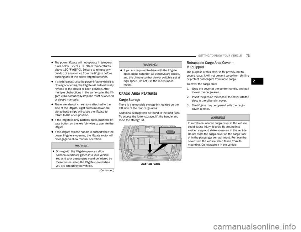
There is a removable storage bin located on the
left side of the rear cargo area.
Additional storage can be found in the load floor.
To access the lower storage, lift the handle and
raise the storage lid.
Load Floor Handle
Retractable Cargo Area Cover —
If Equipped
The purpose of this cover is for privacy, not to
secure loads. It will not prevent cargo from shifting
or protect passengers from loose cargo.
To cover the cargo area:
1. Grab the cover at the center handle, and pull it over the cargo area.
2. Insert the pins on the ends of the cover into the slots in the pillar trim cover.
3. The liftgate may be opened with the cargo cover in place.
WARNING!
Driving with the liftgate open can allow
poisonous exhaust gases into your vehicle.
You and your passengers could be injured by
these fumes. Keep the liftgate closed when
you are operating the vehicle.
If you are required to drive with the liftgate
open, make sure that all windows are closed,
and the climate control blower switch is set at
high speed. Do not use the recirculation
mode.
WARNING!
WARNING!
In a collision, a loose cargo cover in the vehicle
could cause injury. It could fly around in a
sudden stop and strike someone in the vehicle.
Do not store the cargo cover on the cargo floor
or in the passenger compartment. Remove the
cover from the vehicle when taken from its
mounting. Do not store it in the vehicle.
2
23_WD_OM_EN_USC_t.book Page 73
Page 76 of 328
74GETTING TO KNOW YOUR VEHICLE
(Continued)
Cargo Tie-Down Hooks
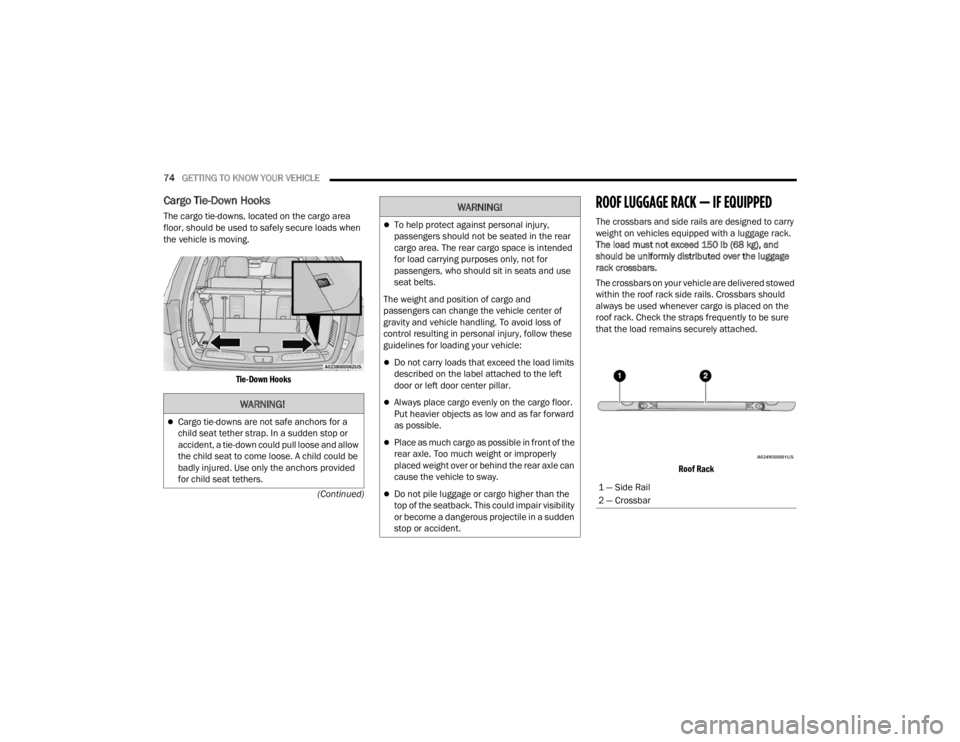
The cargo tie-downs, located on the cargo area
floor, should be used to safely secure loads when
the vehicle is moving.
Tie-Down Hooks
ROOF LUGGAGE RACK — IF EQUIPPED
The crossbars and side rails are designed to carry
weight on vehicles equipped with a luggage rack.
The load must not exceed 150 lb (68 kg), and
should be uniformly distributed over the luggage
rack crossbars.
The crossbars on your vehicle are delivered stowed
within the roof rack side rails. Crossbars should
always be used whenever cargo is placed on the
roof rack. Check the straps frequently to be sure
that the load remains securely attached.
Roof Rack
WARNING!
Cargo tie-downs are not safe anchors for a
child seat tether strap. In a sudden stop or
accident, a tie-down could pull loose and allow
the child seat to come loose. A child could be
badly injured. Use only the anchors provided
for child seat tethers.
To help protect against personal injury,
passengers should not be seated in the rear
cargo area. The rear cargo space is intended
for load carrying purposes only, not for
passengers, who should sit in seats and use
seat belts.
The weight and position of cargo and
passengers can change the vehicle center of
gravity and vehicle handling. To avoid loss of
control resulting in personal injury, follow these
guidelines for loading your vehicle:
Do not carry loads that exceed the load limits
described on the label attached to the left
door or left door center pillar.
Always place cargo evenly on the cargo floor.
Put heavier objects as low and as far forward
as possible.
Place as much cargo as possible in front of the
rear axle. Too much weight or improperly
placed weight over or behind the rear axle can
cause the vehicle to sway.
Do not pile luggage or cargo higher than the
top of the seatback. This could impair visibility
or become a dangerous projectile in a sudden
stop or accident.
WARNING!
1 — Side Rail
2 — Crossbar
23_WD_OM_EN_USC_t.book Page 74