Drive modes DODGE DURANGO 2023 Owners Manual
[x] Cancel search | Manufacturer: DODGE, Model Year: 2023, Model line: DURANGO, Model: DODGE DURANGO 2023Pages: 328, PDF Size: 13.82 MB
Page 18 of 328
16GETTING TO KNOW YOUR VEHICLE
SENTRY KEY
The Sentry Key Immobilizer system prevents
unauthorized vehicle operation by disabling the
engine. The system does not need to be armed or
activated. Operation is automatic, regardless of
whether the vehicle is locked or unlocked.
The system uses a key fob, keyless push button
ignition and a Radio Frequency (RF) receiver to
prevent unauthorized vehicle operation. Therefore,
only key fobs that are programmed to the vehicle
can be used to start and operate the vehicle. The
system will shut the engine off in two seconds if an
invalid key fob is used to start the engine.
After placing the ignition switch in the ON/RUN
position, the Vehicle Security Light will turn on for
three seconds for a bulb check. If the light remains
on after the bulb check, it indicates that there is a
problem with the electronics. In addition, if the light
begins to flash after the bulb check, it indicates
that someone used an invalid key fob to start the
engine. Either of these conditions will result in the
engine being shut off after two seconds.
If the Vehicle Security Light turns on during normal
vehicle operation (vehicle running for longer than
10 seconds), it indicates that there is a fault in the
electronics. Should this occur, have the vehicle
serviced as soon as possible by an authorized
dealer. All of the key fobs provided with your new vehicle
have been programmed to the vehicle electronics
Ú
page 312.
NOTE:A key fob that has not been programmed is also
considered an invalid key.
IGNITION SWITCH
KEYLESS ENTER ‘N GO™ IGNITION
This feature allows the driver to operate the
ignition switch with the push of a button as long as
the key fob is in the passenger compartment.
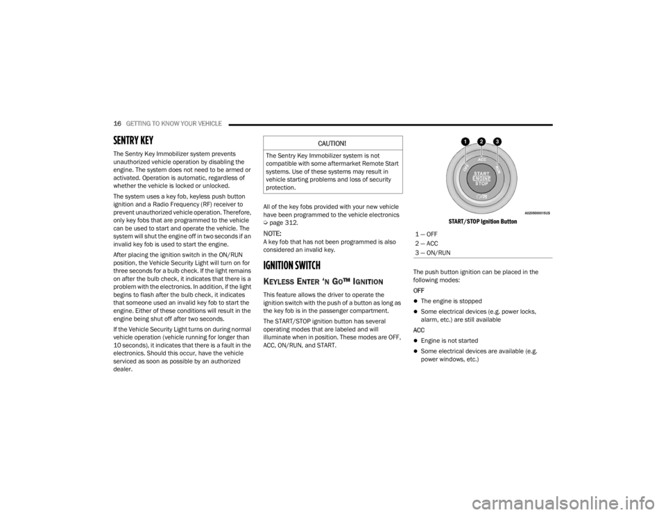
The START/STOP ignition button has several
operating modes that are labeled and will
illuminate when in position. These modes are OFF,
ACC, ON/RUN, and START.
START/STOP Ignition Button
The push button ignition can be placed in the
following modes:
OFFThe engine is stopped
Some electrical devices (e.g. power locks,
alarm, etc.) are still available
ACC
Engine is not started
Some electrical devices are available (e.g.
power windows, etc.)
CAUTION!
The Sentry Key Immobilizer system is not
compatible with some aftermarket Remote Start
systems. Use of these systems may result in
vehicle starting problems and loss of security
protection.
1 — OFF
2 — ACC
3 — ON/RUN
23_WD_OM_EN_USC_t.book Page 16
Page 113 of 328
STARTING AND OPERATING111
4. After the AWD LOW position indicator light is on (not flashing), shift the transmission back into
gear.
NOTE:
If steps 1 or 2 of either the “Preferred” or “Alter -
nate Procedure” are not satisfied prior to
attempting the shift or if they no longer are
being met while the shift attempt is in process,
the desired position indicator light will flash
continuously while the original position indicator
light is on, until all requirements have been met.
The ignition switch must be in the ON/RUN posi -
tion for a shift to take place and for the position
indicator lights to be operable. If the ignition
switch is not in the ON/RUN position, then the
shift will not take place and no position indicator
lights will be on or flashing.
N (Neutral) Shift Procedure
For information regarding the transfer case N
(Neutral) shift procedure Ú page 148.
TOW N GO — IF EQUIPPED
Tow N Go combines the capabilities of the vehicle
control systems, along with driver input, to provide
optimum performance for road conditions.
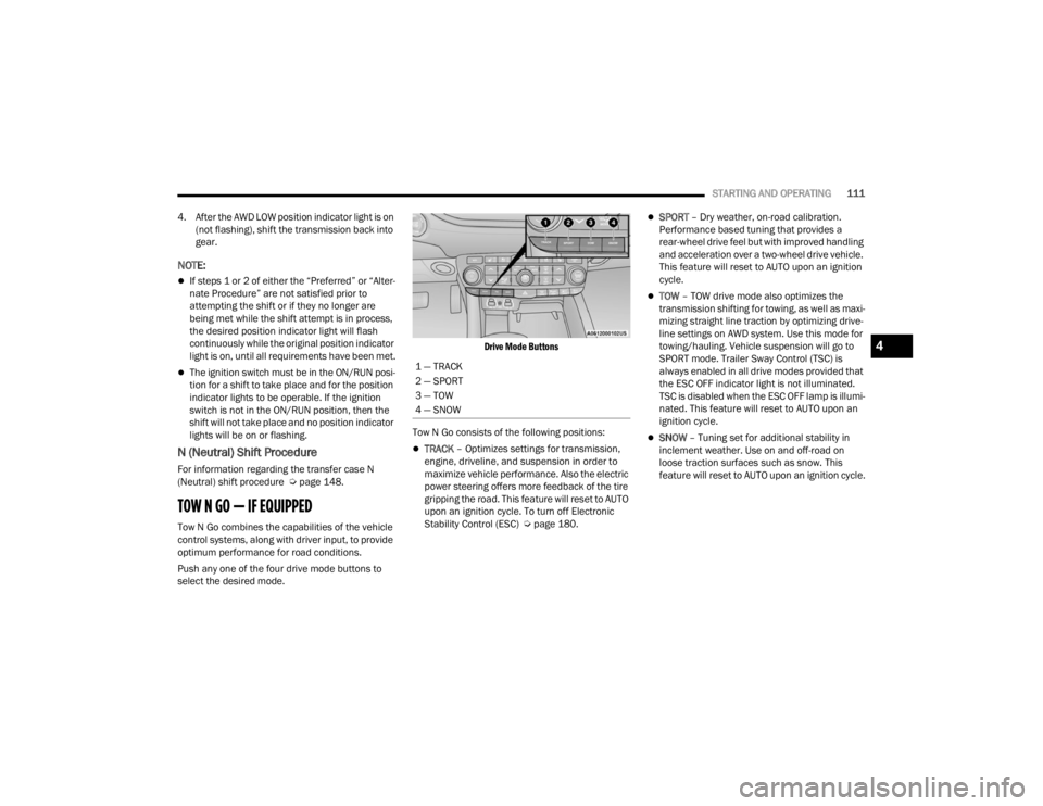
Push any one of the four drive mode buttons to
select the desired mode.
Drive Mode Buttons
Tow N Go consists of the following positions:
TRACK – Optimizes settings for transmission,
engine, driveline, and suspension in order to
maximize vehicle performance. Also the electric
power steering offers more feedback of the tire
gripping the road. This feature will reset to AUTO
upon an ignition cycle. To turn off Electronic
Stability Control (ESC) Ú page 180.
SPORT – Dry weather, on-road calibration.
Performance based tuning that provides a
rear-wheel drive feel but with improved handling
and acceleration over a two-wheel drive vehicle.
This feature will reset to AUTO upon an ignition
cycle.
TOW – TOW drive mode also optimizes the
transmission shifting for towing, as well as maxi -
mizing straight line traction by optimizing drive -
line settings on AWD system. Use this mode for
towing/hauling. Vehicle suspension will go to
SPORT mode. Trailer Sway Control (TSC) is
always enabled in all drive modes provided that
the ESC OFF indicator light is not illuminated.
TSC is disabled when the ESC OFF lamp is illumi -
nated. This feature will reset to AUTO upon an
ignition cycle.
SNOW – Tuning set for additional stability in
inclement weather. Use on and off-road on
loose traction surfaces such as snow. This
feature will reset to AUTO upon an ignition cycle.
1 — TRACK
2 — SPORT
3 — TOW
4 — SNOW
4
23_WD_OM_EN_USC_t.book Page 111
Page 114 of 328
112STARTING AND OPERATING
GUIDELINES FOR TRACK USE
NOTE:The standard Black Brembo Brake Pads are not
recommended for track use. Only the Red Brembo
Performance SRT brake pads are appropriate for
track use.
If your vehicle is equipped with Drive Modes,
they will alter the vehicle’s performance in
various driving situations. It is recommended
that your vehicle operates in SPORT or TRACK
modes during the track event.
Prior to each track event, verify all fluids are at
the correct levels.
Prior to each track event, verify the front and
rear brake pads have more than half pad thick -
ness remaining. If the brake pads require
changing, complete a brake burnish procedure
prior to track outing at full pace.
NOTE:Use of DOT 4 brake fluid is suggested for extended
track usage due to increased thermal capacity.
At the conclusion of each track event, it is
recommended that a brake bleed procedure is
performed to maintain the pedal feel and stop -
ping capability of your Brembo High Perfor -
mance brake system.
It is recommended that each track outing
should end with a minimum of one cooldown lap
using minimal braking.
It is recommended to check oil temperature
after each track session. If the oil is still above
225°F (107°C), do another cooldown lap if
possible, or keep the engine running and let idle
until below 225°F (107°C), in order to prevent
heat soaking of the engine. Ensure temperature
is reducing and do not leave vehicle gauges
unattended while idling just after a track
session.
It is recommended that the suspension system,
brake system, prop shaft, and half shaft boots
be checked for wear or damage after every track
event.
Track usage results in increased operating
temperatures of the engine, transmission, drive -
line and brake system. This may affect Noise
Vibration Harshness (NVH) countermeasures
designed into your vehicle. New components
may need to be installed to return the system to
the original NVH performance.
Tire pressure:
Recommended tire pressure of 33 psi
(230 kPa) when tires are cold, or below
42 psi (290 kPa) when hot.
NOTE:It is recommended that you target below 42 psi
(290 kPa) when tires are hot at the conclusion of
each track session. Starting at 33 psi (230 kPa)
cold and adjusting based on ambient and track
conditions is recommended. Tire pressure can be
monitored via the instrument cluster display and
can assist with adjustments.
Track burnishing your brakes
To avoid “green lining fade” during track use, the
brake pads and rotors must have a thermal
burnish for factory-installed components or when
new brake friction components are installed:
1. Use one track session to burnish brakes by driving at 75% speed. Brake at approximately
0.60 - 0.80g max without Anti-Lock Brake
System (ABS) intervention.
2. Complete one lap in this manner until you start smelling the brakes. Continue for another half
lap at speed, then complete a two lap
cooldown with minimal brake applications.
Ensure the brakes are not smoking. If they are,
complete another cooldown lap.
3. Getting the brakes to smoke is an indication that the brakes have overheated and may
negatively affect future track usage.
23_WD_OM_EN_USC_t.book Page 112
Page 121 of 328
STARTING AND OPERATING119
The instrument cluster display will return to the last
display selected after five seconds of no ACC
display activity.
Activating Adaptive Cruise Control (ACC)
The minimum set speed for the ACC system is
20 mph (32 km/h).
When the system is turned on and in the ready
state, the instrument cluster display will read “ACC
Ready.”
When the system is off, the instrument cluster
display will read “Adaptive Cruise Control (ACC)
Off.”
NOTE:You cannot engage ACC under the following condi -
tions:
When in 4WD Low
When the brakes are applied
When the parking brake is applied
When the automatic transmission is in PARK,
REVERSE or NEUTRAL
When the vehicle speed is below the minimum
speed range
When the brakes are overheated
When the driver’s door is open at low speeds
When the driver’s seat belt is unbuckled at low
speeds
When there is a stationary vehicle in front of
your vehicle in close proximity
To Activate/Deactivate
Push and release the Adaptive Cruise Control
(ACC) on/off button. The ACC menu in the
instrument cluster displays “ACC Ready.”
To turn the system off, push and release the
Adaptive Cruise Control (ACC) on/off button again.
At this time, the system will turn off and the
instrument cluster displays “Adaptive Cruise
Control (ACC) Off.”
To Set A Desired Speed
When the vehicle reaches the speed desired, push
the SET (+) button or the SET (-) button and
release. The instrument cluster display will show
the set speed.
NOTE:Fixed Speed Cruise Control can be used without
ACC enabled. To change between the different
modes, push the ACC on/off button which turns
the ACC and the Fixed Speed Cruise Control off.
Pushing the Fixed Speed Cruise Control on/off
button will result in turning on (changing to) Fixed
Speed Cruise Control mode.
If ACC is set when the vehicle speed is below
20 mph (32 km/h), the set speed will default to
20 mph (32 km/h).
NOTE:Fixed Speed Cruise Control cannot be set below
20 mph (32 km/h).
If either system is set when the vehicle speed is
above 20 mph (32 km/h), the set speed shall be
the current speed of the vehicle.
WARNING!
Leaving the Adaptive Cruise Control (ACC)
system on when not in use is dangerous. You
could accidentally set the system or cause it to
go faster than you want. You could lose control
and have a collision. Always leave the system off
when you are not using it.
WARNING!
In Fixed Speed Cruise Control mode (ACC not
enabled), the system will not react to vehicles
ahead. In addition, the proximity warning does
not activate and no alarm will sound even if you
are too close to the vehicle ahead since neither
the presence of the vehicle ahead nor the
vehicle-to-vehicle distance is detected. Be sure
to maintain a safe distance between your vehicle
and the vehicle ahead. Always be aware which
mode is selected.4
23_WD_OM_EN_USC_t.book Page 119
Page 136 of 328
134STARTING AND OPERATING
CHANGING LANESENSE STATUS
The LaneSense system has settings to adjust the
intensity of the torque warning and the warning
zone sensitivity (early/late) that you can configure
through the Uconnect system Ú page 153.
NOTE:
When enabled the system operates above
37 mph (60 km/h) and below 112 mph
(180 km/h).
The warnings are disabled with use of the turn
signal.
The system will not apply torque to the steering
wheel whenever a safety system engages
(Anti-Lock Brakes, Traction Control System,
Electronic Stability Control, Forward Collision
Warning, etc.).
PARKVIEW REAR BACK UP CAMERA
Your vehicle is equipped with the ParkView Rear
Back Up Camera that allows you to see an on-screen
image of the rear surroundings of your vehicle
whenever the gear selector is put into REVERSE. The
image will be displayed on the Navigation/
Multimedia radio display screen along with a caution
note to “Check Entire Surroundings” across the top
of the screen. After five seconds this note will
disappear. The ParkView camera is located on the
rear of the vehicle above the rear license plate.
When the vehicle is shifted out of REVERSE with
camera delay turned off, the rear camera mode is
exited and the previous screen appears.
Manual Activation Of The Back Up Camera
1. Press the Vehicle Menu button located at the
bottom of the Uconnect display. Then select
the Controls tab.
2. Press the Rear View Camera button to turn the Rear View Camera system on.
3. Alternatively, the Rear View Camera feature can be enabled by pressing the Rear View
Camera button in the App Drawer.
NOTE:The ParkView Rear Back Up Camera has program -
mable modes of operation that may be selected
through the Uconnect system Ú page 153. In
certain radio configurations, these modes of oper -
ation will be found in the Camera section of the
vehicle settings menu.
When the vehicle is shifted out of REVERSE with
camera delay turned off, the rear camera mode is
exited and the previous screen appears. When the
vehicle is shifted out of REVERSE with camera
delay turned on, the camera image will continue to
be displayed for up to 10 seconds after shifting out
of REVERSE unless the following conditions occur:
the vehicle speed exceeds 8 mph (13 km/h), the
vehicle is shifted into PARK, the vehicle’s ignition is
placed in the OFF position, or the touchscreen X button to disable the display of the Rear View
Camera is pressed.
When enabled, active guidelines are overlaid on
the image to illustrate the width of the vehicle and
its projected back up path based on the steering
wheel position. A dashed center line overlay
indicates the center of the vehicle to assist with
parking or aligning to a hitch/receiver. Different
colored zones indicate the distance to the rear of
the vehicle.
The following table shows the approximate
distances for each zone:
Rear View Camera — Viewing At Speed
When the vehicle is in PARK, NEUTRAL or
DRIVE, the Rear View Camera can be
activated with the Rear View Camera
button in the Controls tab of the Vehicle
Menu. This feature allows the customer to monitor
the area directly behind the vehicle (or trailer, if
equipped) for up to 10 seconds while driving. If the
vehicle speed remains below 8 mph (13 km/h), Zone
Distance To The Rear Of
The Vehicle
Red 0 - 1 ft (0 - 30 cm)
Yellow 1 ft - 6.5 ft (30 cm - 2 m)
Green 6.5 ft or greater
(2 m or greater)
23_WD_OM_EN_USC_t.book Page 134
Page 182 of 328
180SAFETY
(Continued)
Electronic Stability Control (ESC)
ESC enhances directional control and stability of
the vehicle under various driving conditions. ESC
corrects for oversteering or understeering of the
vehicle by applying the brake of the appropriate
wheel(s) to counteract the previous conditions.
Engine power may also be reduced to help the
vehicle maintain the desired path.
Oversteer — when the vehicle is turning more
than appropriate for the steering wheel position.
Understeer — when the vehicle is turning less
than appropriate for the steering wheel position.
ESC uses sensors in the vehicle to determine the
vehicle path intended by the driver and compares
it to the actual path of the vehicle. When the actual
path does not match the intended path, ESC
applies the brake of the appropriate wheel to
assist in counteracting the oversteer or understeer
condition.
The ESC Activation/Malfunction Indicator Light
located in the instrument cluster will start to flash
as soon as the ESC system becomes active. The
ESC Activation/Malfunction Indicator Light also
flashes when the Traction Control System (TCS) is
active. If the ESC Activation/Malfunction Indicator
Light begins to flash during acceleration, ease up
on the accelerator and apply as little throttle as
possible. Be sure to adapt your speed and driving
to the prevailing road conditions.
ESC Operating Modes
Depending upon model and mode of operation, the
ESC system may have multiple operating modes.
ESC On
This is the normal operating mode for the ESC.
Whenever the vehicle is started, the ESC system
will be in this mode. This mode should be used for
most driving conditions. Alternate ESC modes
should only be used for specific reasons as noted
in the following paragraphs.
WARNING!
Electronic Stability Control (ESC) cannot
prevent the natural laws of physics from
acting on the vehicle, nor can it increase the
traction afforded by prevailing road condi -
tions. ESC cannot prevent accidents, including
those resulting from excessive speed in turns,
driving on very slippery surfaces, or hydro -
planing. ESC also cannot prevent accidents
resulting from loss of vehicle control due to
inappropriate driver input for the conditions.
Only a safe, attentive, and skillful driver can
prevent accidents. The capabilities of an ESC
equipped vehicle must never be exploited in a
reckless or dangerous manner which could
jeopardize the user’s safety or the safety of
others.Vehicle modifications, or failure to properly
maintain your vehicle, may change the
handling characteristics of your vehicle, and
may negatively affect the performance of the
ESC system. Changes to the steering system,
suspension, braking system, tire type and size
or wheel size may adversely affect ESC perfor -
mance. Improperly inflated and unevenly worn
tires may also degrade ESC performance. Any
vehicle modification or poor vehicle mainte -
nance that reduces the effectiveness of the
ESC system can increase the risk of loss of
vehicle control, vehicle rollover, personal
injury and death.
WARNING!
23_WD_OM_EN_USC_t.book Page 180
Page 183 of 328
SAFETY181
Partial Off
This mode may be useful if the vehicle becomes
stuck. This mode may modify TCS and ESC
thresholds for activation, which allows for more
wheel spin than normally allowed.
To enter the “Partial Off” mode, momentarily push
the ESC OFF button and the ESC OFF Indicator
Light will illuminate. To turn the ESC on again,
momentarily push the ESC OFF button and the ESC
OFF Indicator Light will turn off.
NOTE:For vehicles with multiple partial ESC modes, the
push and release of the button may toggle the ESC
modes. Multiple attempts may be required to
return to "ESC On" mode.
ESC Activation/Malfunction Indicator Light
And ESC OFF Indicator Light
The ESC Activation/Malfunction Indicator
Light in the instrument cluster will come
on when the ignition is placed in the ON/
RUN mode. It should go out with the
engine running. If the ESC Activation/Malfunction
Indicator Light comes on continuously with the
engine running, a malfunction has been detected
in the ESC system. If this light remains on after
several ignition cycles, and the vehicle has been
driven several miles (kilometers) at speeds greater
than 30 mph (48 km/h), see an authorized dealer
as soon as possible to have the problem
diagnosed and corrected.
The ESC Activation/Malfunction Indicator Light
starts to flash as soon as the tires lose traction and
the ESC system becomes active. The ESC
Activation/Malfunction Indicator Light also flashes
when TCS is active. If the ESC Activation/
Malfunction Indicator Light begins to flash during
acceleration, ease up on the accelerator and apply
as little throttle as possible. Be sure to adapt your
speed and driving to the prevailing road conditions.
The ESC OFF Indicator Light indicates
that the Electronic Stability Control (ESC)
is in a reduced mode.
NOTE:
The ESC Activation/Malfunction Indicator Light
and the ESC OFF Indicator Light come on
momentarily each time the ignition placed in the
ON position.
Each time the ignition is placed in the ON posi -
tion, the ESC system will be on even if it was
turned off previously.
The ESC system will make buzzing or clicking
sounds when it is active. This is normal; the
sounds will stop when ESC becomes inactive
following the maneuver that caused the ESC
activation.
Hill Start Assist (HSA)
HSA is designed to mitigate roll back from a
complete stop while on an incline. If the driver
releases the brake while stopped on an incline,
HSA will continue to hold the brake pressure for a
short period. If the driver does not apply the
throttle before this time expires, the system will
release brake pressure and the vehicle will roll
down the hill as normal.
The following conditions must be met in order for
HSA to activate:
The feature must be enabled.
The vehicle must be stopped.
WARNING!
When in “Partial Off” mode, the TCS function -
ality of ESC, except for the limited slip feature
described in the TCS section, has been
disabled and the ESC OFF Indicator Light will
be illuminated. When in “Partial Off” mode,
the engine power reduction feature of TCS is
disabled, and the enhanced vehicle stability
offered by the ESC system is reduced.
Trailer Sway Control (TSC) is disabled when
the ESC system is in the “Partial Off” mode.
6
23_WD_OM_EN_USC_t.book Page 181
Page 185 of 328
SAFETY183
spinning wheel. This will allow more engine power
to be applied to the wheel that is not spinning. BLD
may remain enabled even if TCS and ESC are in
reduced modes.
Trailer Sway Control (TSC)
TSC uses sensors in the vehicle to recognize an
excessively swaying trailer and will take the
appropriate actions to attempt to stop the sway.
Note that TSC cannot stop all trailers from swaying.
Always use caution when towing a trailer and follow
the trailer tongue weight recommendations
Ú page 137.
When TSC is functioning, the ESC Activation/
Malfunction Indicator Light will flash, the engine
power may be reduced and you may feel the
brakes being applied to individual wheels to
attempt to stop the trailer from swaying. TSC is
disabled when the ESC system is in the “Partial
Off” mode.
AUXILIARY DRIVING SYSTEMS
BLIND SPOT MONITORING (BS M) —
I
F EQUIPPED
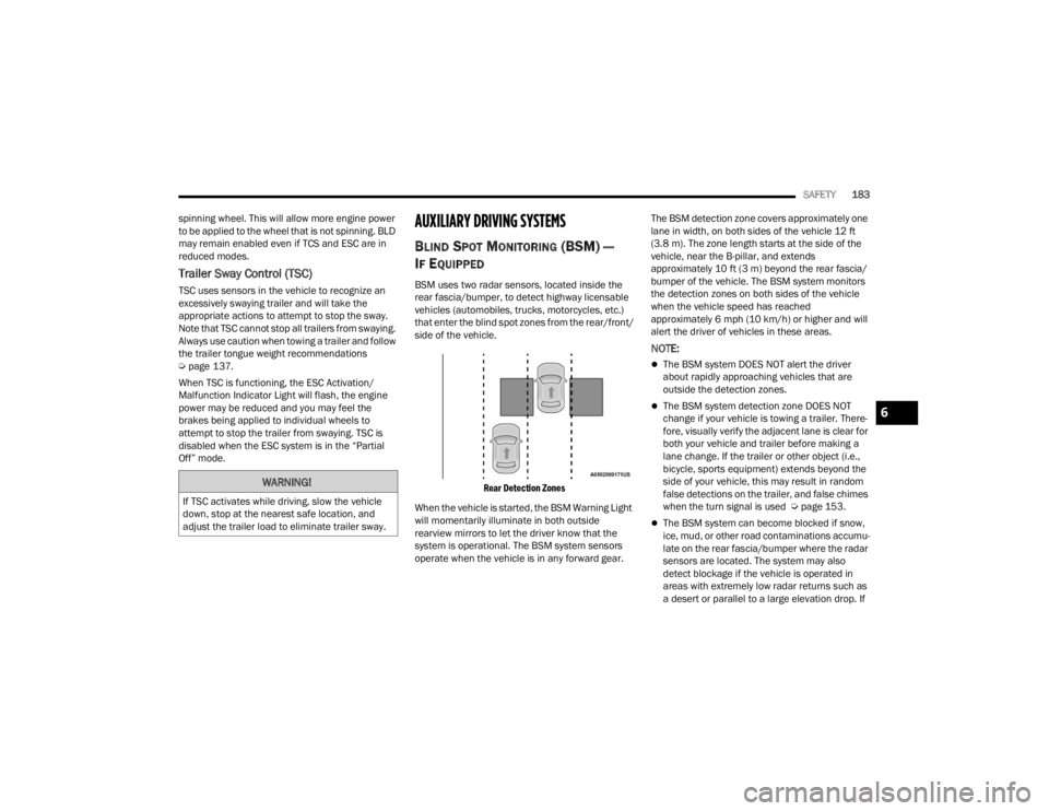
BSM uses two radar sensors, located inside the
rear fascia/bumper, to detect highway licensable
vehicles (automobiles, trucks, motorcycles, etc.)
that enter the blind spot zones from the rear/front/
side of the vehicle.
Rear Detection Zones
When the vehicle is started, the BSM Warning Light
will momentarily illuminate in both outside
rearview mirrors to let the driver know that the
system is operational. The BSM system sensors
operate when the vehicle is in any forward gear. The BSM detection zone covers approximately one
lane in width, on both sides of the vehicle 12 ft
(3.8 m). The zone length starts at the side of the
vehicle, near the B-pillar, and extends
approximately 10 ft (3 m) beyond the rear fascia/
bumper of the vehicle. The BSM system monitors
the detection zones on both sides of the vehicle
when the vehicle speed has reached
approximately 6 mph (10 km/h) or higher and will
alert the driver of vehicles in these areas.
NOTE:
The BSM system DOES NOT alert the driver
about rapidly approaching vehicles that are
outside the detection zones.
The BSM system detection zone DOES NOT
change if your vehicle is towing a trailer. There
-
fore, visually verify the adjacent lane is clear for
both your vehicle and trailer before making a
lane change. If the trailer or other object (i.e.,
bicycle, sports equipment) extends beyond the
side of your vehicle, this may result in random
false detections on the trailer, and false chimes
when the turn signal is used Ú page 153.
The BSM system can become blocked if snow,
ice, mud, or other road contaminations accumu -
late on the rear fascia/bumper where the radar
sensors are located. The system may also
detect blockage if the vehicle is operated in
areas with extremely low radar returns such as
a desert or parallel to a large elevation drop. If
WARNING!
If TSC activates while driving, slow the vehicle
down, stop at the nearest safe location, and
adjust the trailer load to eliminate trailer sway.
6
23_WD_OM_EN_USC_t.book Page 183
Page 188 of 328
186SAFETY
NOTE:In a parking lot situation, oncoming vehicles can be
blocked by vehicles parked on either side. If the
sensors are blocked by other structures or
vehicles, the system will not be able to alert the
driver.
Blind Spot Modes
Blind Spot has three selectable modes of
operation that are available in the Uconnect
system.
Blind Spot Alert Lights Only
When operating in Blind Spot Alert mode, the BSM
system will provide a visual alert in the appropriate
side view mirror based on a detected object.
However, when the system is operating in Rear
Cross Path (RCP) mode, the system will respond with both visual and audible alerts when a
detected object is present. Whenever an audible
alert is requested, the radio is muted.
Blind Spot Alert Lights/Chime
When operating in Blind Spot Alert Lights/Chime
mode, the BSM system will provide a visual alert in
the appropriate side view mirror based on a
detected object. If the turn signal is then activated,
and it corresponds to an alert present on that side
of the vehicle, an audible chime will also be
sounded. Whenever a turn signal and detected
object are present on the same side at the same
time, both the visual and audible alerts will be
issued. In addition to the audible alert the radio (if
on) will also be muted.
NOTE:Whenever an audible alert is requested by the
BSM system, the radio is also muted.
When the system is in RCP, the system shall
respond with both visual and audible alerts when a
detected object is present. Whenever an audible
alert is requested, the radio is also muted. Turn/
hazard signal status is ignored; the RCP state
always requests the chime.
Blind Spot Alert Off
When the BSM system is turned off there will be no
visual or audible alerts from either the BSM or RCP
systems.
NOTE:The BSM system will store the current operating
mode when the vehicle is shut off. Each time the
vehicle is started the previously stored mode will
be recalled and used.
FORWARD COLLISION WARNING (FCW)
W
ITH MITIGATION
FCW with Mitigation provides the driver with
audible warnings, visual warnings (within the
instrument cluster display), and may apply a brake
jerk to warn the driver when it detects a potential
frontal collision. The warnings and limited braking
are intended to provide the driver with enough time
to react, avoid or mitigate the potential collision.
NOTE:FCW monitors the information from the forward
looking sensors as well as the Electronic Brake
Controller (EBC) to calculate the probability of a
forward collision. When the system determines
that a forward collision is probable, the driver will
be provided with audible and visual warnings and
may provide a brake jerk warning. If the driver does
not take action based upon these progressive
warnings, then the system will provide a limited
level of active braking to help slow the vehicle and
mitigate the potential forward collision. If the driver
reacts to the warnings by braking and the system
determines that the driver intends to avoid the
collision by braking but has not applied sufficient
WARNING!
Rear Cross Path (RCP) detection is not a backup
aid system. It is intended to be used to help a
driver detect an oncoming vehicle in a parking
lot situation. Drivers must be careful when
backing up, even when using RCP. Always check
carefully behind your vehicle, look behind you,
and be sure to check for pedestrians, animals,
other vehicles, obstructions, and blind spots
before backing up. Failure to do so can result in
serious injury or death.
23_WD_OM_EN_USC_t.book Page 186