warning lights DODGE DURANGO 2023 Owners Manual
[x] Cancel search | Manufacturer: DODGE, Model Year: 2023, Model line: DURANGO, Model: DODGE DURANGO 2023Pages: 328, PDF Size: 13.82 MB
Page 5 of 328
3
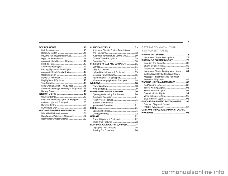
EXTERIOR LIGHTS.................................................. 45 Multifunction Lever ..........................................45
Headlight Switch ..............................................45
Daytime Running Lights (DRLs) ......................46
High/Low Beam Switch....................................46
Automatic High Beam — If Equipped ..............47
Flash-To-Pass....................................................47
Automatic Headlights ......................................47
Parking Lights And Panel Lights ......................47
Automatic Headlights With Wipers..................47
Headlight Delay ................................................48
Lights-On Reminder..........................................48
Fog Lights — If Equipped ..................................48
Turn Signals ......................................................48
Lane Change Assist — If Equipped ..................48
Automatic Headlight Leveling — If Equipped ..49
Battery Saver ....................................................49
INTERIOR LIGHTS ................................................. 49
Courtesy Lights .................................................49
Front Map/Reading Lights —If Equipped ........49
Ambient Light — If Equipped ............................50
Dimmer Control ................................................50
Illuminated Entry ..............................................51
WINDSHIELD WIPERS AND WASHERS .............. 51
Windshield Wiper Operation ...........................51
Rain Sensing Wipers — If Equipped ...............52
Rear Window Wiper/Washer ..........................53 CLIMATE CONTROLS..............................................53
Automatic Climate Control Descriptions
And Functions ...................................................53
Automatic Temperature Control (ATC) ............59
Climate Voice Recognition ...............................59
Operating Tips .................................................60
INTERIOR STORAGE AND EQUIPMENT ............... 61
Storage..............................................................61
USB/AUX Control .............................................63
Lighted Cupholders — If Equipped ..................65
Electrical Power Outlets ...................................65
Power Inverter — If Equipped ..........................67
Wireless Charging Pad —If Equipped .............68
WINDOWS ..............................................................68
Power Windows ................................................68
Wind Buffeting .................................................70
POWER SUNROOF — IF EQUIPPED ...................... 70
Opening And Closing The Sunroof...................70
Sunshade Operation ........................................71
Pinch Protect Feature ......................................71
Sunroof Maintenance ......................................71
Ignition Off Operation.......................................71
HOOD .......................................................................71
Opening The Hood............................................71
Closing The Hood .............................................72
LIFTGATE ................................................................. 72
Power Liftgate — If Equipped ...........................72
Cargo Area Features .......................................73
ROOF LUGGAGE RACK — IF EQUIPPED ............... 74
Deploying The Crossbars .................................75
Stowing The Crossbars ....................................76
GETTING TO KNOW YOUR
INSTRUMENT PANEL
INSTRUMENT CLUSTER ........................................ 78Instrument Cluster Descriptions ..................... 79
INSTRUMENT CLUSTER DISPLAY ........................ 79
Location And Controls...................................... 80
Engine Oil Life Reset ....................................... 82
Display And Messages ..................................... 83
Instrument Cluster Display Menu Items ........ 84
Battery Saver On/Battery Saver Mode
Message — Electrical Load Reduction
Actions — If Equipped ..................................... 87
WARNING LIGHTS AND MESSAGES ................... 88
Red Warning Lights ..........................................88
Yellow Warning Lights ...................................... 91
Yellow Indicator Lights ..................................... 94
Green Indicator Lights ..................................... 94
White Indicator Lights ...................................... 95
Blue Indicator Lights ........................................ 95
ONBOARD DIAGNOSTIC SYSTEM — OBD II ....... 96
Onboard Diagnostic System
(OBD II) Cybersecurity ...................................... 96
EMISSIONS INSPECTION AND MAINTENANCE
PROGRAMS ........................................................... 96
23_WD_OM_EN_USC_t.book Page 3
Page 11 of 328
9
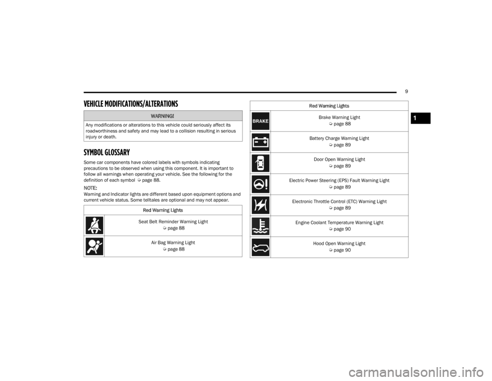
VEHICLE MODIFICATIONS/ALTERATIONS
SYMBOL GLOSSARY
Some car components have colored labels with symbols indicating
precautions to be observed when using this component. It is important to
follow all warnings when operating your vehicle. See the following for the
definition of each symbol Úpage 88.
NOTE:Warning and Indicator lights are different based upon equipment options and
current vehicle status. Some telltales are optional and may not appear.
WARNING!
Any modifications or alterations to this vehicle could seriously affect its
roadworthiness and safety and may lead to a collision resulting in serious
injury or death.
Red Warning Lights
Seat Belt Reminder Warning Light Úpage 88
Air Bag Warning Light Úpage 88
Brake Warning Light
Úpage 88
Battery Charge Warning Light Úpage 89
Door Open Warning Light Úpage 89
Electric Power Steering (EPS) Fault Warning Light Úpage 89
Electronic Throttle Control (ETC) Warning Light Úpage 89
Engine Coolant Temperature Warning Light Úpage 90
Hood Open Warning Light Úpage 90
Red Warning Lights1
23_WD_OM_EN_USC_t.book Page 9
Page 12 of 328
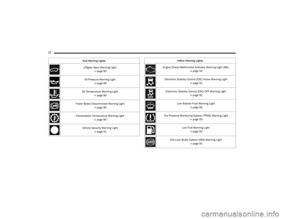
10 Liftgate Open Warning Light Úpage 90
Oil Pressure Warning Light Úpage 90
Oil Temperature Warning Light Úpage 90
Trailer Brake Disconnected Warning Light Úpage 90
Transmission Temperature Warning Light Úpage 90
Vehicle Security Warning Light Úpage 91
Red Warning Lights
Yellow Warning Lights
Engine Check/Malfunction Indicator Warning Light (MIL) Úpage 92
Electronic Stability Control (ESC) Active Warning Light Úpage 91
Electronic Stability Control (ESC) OFF Warning Light Úpage 92
Low Washer Fluid Warning Light Úpage 92
Tire Pressure Monitoring System (TPMS) Warning Light Úpage 93
Low Fuel Warning Light Úpage 92
Anti-Lock Brake System (ABS) Warning Light Úpage 91
23_WD_OM_EN_USC_t.book Page 10
Page 13 of 328
11
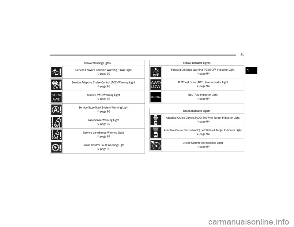
Service Forward Collision Warning (FCW) Light Úpage 92
Service Adaptive Cruise Control (ACC) Warning Light Úpage 93
Service AWD Warning Light Úpage 93
Service Stop/Start System Warning Light Úpage 93
LaneSense Warning Light Úpage 92
Service LaneSense Warning Light Úpage 92
Cruise Control Fault Warning Light Úpage 93
Yellow Warning Lights
Yellow Indicator Lights
Forward Collision Warning (FCW) OFF Indicator Light Úpage 94
All Wheel Drive (AWD) Low Indicator Light Úpage 94
NEUTRAL Indicator Light Úpage 94
Green Indicator Lights
Adaptive Cruise Control (ACC) Set With Target Indicator Light Úpage 94
Adaptive Cruise Control (ACC) Set Without Target Indicator Light Úpage 94
Cruise Control Set Indicator Light Úpage 94
1
23_WD_OM_EN_USC_t.book Page 11
Page 20 of 328
18GETTING TO KNOW YOUR VEHICLE
NOTE:Obstructions between the vehicle and key fob may
reduce this range Úpage 312.
HOW TO USE REMOTE START
Push and release the Remote Start button on the
key fob twice within five seconds. The vehicle
doors will lock, the parking lights will flash, and the
horn will chirp twice (if programmed). Then, the
engine will start, and the vehicle will remain in the
Remote Start mode for a 15 minute cycle. Pushing
the Remote Start button a third time shuts the
engine off. To drive the vehicle, push the unlock button, and
with a valid Keyless Enter ‘n Go™ key fob in the
vehicle, place the ignition in the ON/RUN position.
NOTE:
With Remote Start, the engine will only run for
15 minutes.
Remote Start can only be used twice.
If an engine fault is present or fuel level is low,
the vehicle will start and then shut down in 10
seconds.
The parking lights will turn on and remain on
during Remote Start mode.
For security, power window and sunroof (if
equipped) operation is disabled when the
vehicle is in the Remote Start mode.
The ignition must be placed in the ON/RUN posi
-
tion before the Remote Start sequence can be
repeated for a third cycle.
All of the following conditions must be met before
the engine will remote start:
Gear selector in PARK
Doors closed
Hood closed
Liftgate closed
Hazard switch off
Brake pedal not pressed
Battery at an acceptable charge level
Panic button not pressed
System not disabled from previous Remote
Start event
Vehicle Security system indicator flashing
Ignition in OFF position
Fuel level meets minimum requirement
Vehicle Security system is not signaling an intru -
sion
Malfunction Indicator Light (MIL) is not illumi -
nated
WARNING!
Do not start or run an engine in a closed
garage or confined area. Exhaust gas contains
carbon monoxide (CO) which is odorless and
colorless. Carbon monoxide is poisonous and
can cause serious injury or death when
inhaled.
Keep key fobs away from children. Operation
of the Remote Start system, windows, door
locks or other controls could cause serious
injury or death.
23_WD_OM_EN_USC_t.book Page 18
Page 37 of 328
GETTING TO KNOW YOUR VEHICLE35
(Continued)
The Easy Entry/Exit feature is not available
when the driver seat position is less than 0.9 of
an inch (22.7 mm) forward of the rear stop. At
this position, there is no benefit to the driver by
moving the seat for Easy Exit or Easy Entry.
When enabled in Uconnect Settings, Easy Entry
and Easy Exit positions are stored in each Driver
Memory Setting profile Ú page 27.
NOTE:The Easy Entry/Exit feature is enabled (or disabled)
through the programmable features in the
Uconnect system Úpage 153.
HEATED SEATS — IF EQUIPPED
Front Heated Seats — If Equipped
The front heated seats control buttons
are located on the center stack below the
radio screen, or within the Uconnect
system.
Press the heated seat switch once to turn the HI
setting on.
Press the heated seat switch a second time to
turn the MED setting on.
Press the heated seat switch a third time to turn
the LO setting on.
Press the heated seat switch a fourth time to
turn the heating elements off.
NOTE:
Once a heat setting is selected, heat will be felt
within two to five minutes.
The engine must be running for the heated
seats to operate.
The level of heat selected will stay on until the
operator changes it.
For information on use with the Remote Start
system, see Ú page 19.
Rear Heated Seats — If Equipped
The two second row outboard seats may
be equipped with heated seats. There
are two heated seat switches that allow
the rear passengers to operate the seats
independently. The heated seat switches for each
heater are located on the rear of the center
console.
You can choose from HI, LO, or off heat settings.
Amber indicator lights in each switch indicate the
level of heat in use. Two indicator lights will
illuminate for HI, one for LO and none for off.
Push the switch once to turn the HI setting on.
Push the switch a second time to turn the LO
setting on.
Push the switch a third time to turn the heating
elements off.
The level of heat selected will stay on until the
operator changes it.
NOTE:The engine must be running for the heated seats to
operate.
WARNING!
Persons who are unable to feel pain to the
skin because of advanced age, chronic illness,
diabetes, spinal cord injury, medication,
alcohol use, exhaustion or other physical
condition must exercise care when using the
seat heater. It may cause burns even at low
temperatures, especially if used for long
periods of time.
Do not place anything on the seat or seatback
that insulates against heat, such as a blanket
or cushion. This may cause the seat heater to
overheat. Sitting in a seat that has been over -
heated could cause serious burns due to the
increased surface temperature of the seat.
WARNING!
2
23_WD_OM_EN_USC_t.book Page 35
Page 43 of 328
GETTING TO KNOW YOUR VEHICLE41
OUTSIDE MIRRORS WITH TURN SIGNAL —
I
F EQUIPPED
Driver and passenger outside mirrors with turn
signal lighting contain LEDs, which are located in
the lower outer corner of each mirror.
The LEDs are turn signal indicators, which flash
with the corresponding turn signal lights in the
front and rear of the vehicle. Turning on the Hazard
Warning flashers will also activate these LEDs.
OUTSIDE AUTOMATIC DIMMING MIRROR —
I
F EQUIPPED
The driver’s side outside mirror will automatically
adjust for glare from vehicles behind you. This
feature is controlled by the inside automatic
dimming mirror. The mirror will automatically
adjust for headlight glare when the inside mirror
adjusts.
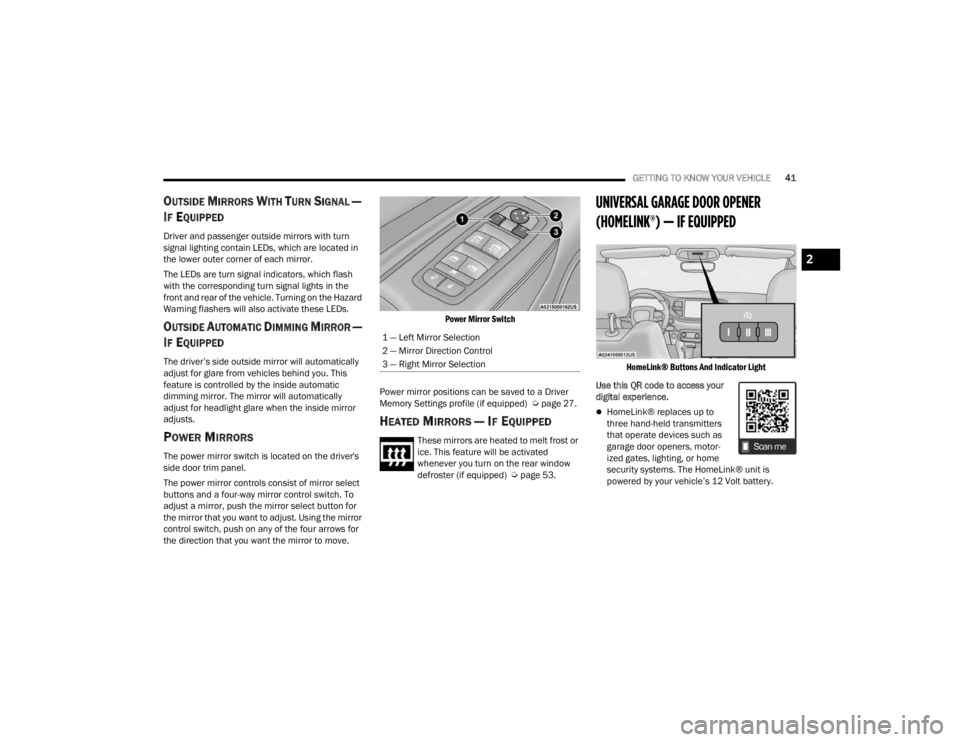
POWER MIRRORS
The power mirror switch is located on the driver's
side door trim panel.
The power mirror controls consist of mirror select
buttons and a four-way mirror control switch. To
adjust a mirror, push the mirror select button for
the mirror that you want to adjust. Using the mirror
control switch, push on any of the four arrows for
the direction that you want the mirror to move.
Power Mirror Switch
Power mirror positions can be saved to a Driver
Memory Settings profile (if equipped) Ú page 27.
HEATED MIRRORS — IF EQUIPPED
These mirrors are heated to melt frost or
ice. This feature will be activated
whenever you turn on the rear window
defroster (if equipped) Úpage 53.
UNIVERSAL GARAGE DOOR OPENER
(HOMELINK®) — IF EQUIPPED
HomeLink® Buttons And Indicator Light
Use this QR code to access your
digital experience.
HomeLink® replaces up to
three hand-held transmitters
that operate devices such as
garage door openers, motor -
ized gates, lighting, or home
security systems. The HomeLink® unit is
powered by your vehicle’s 12 Volt battery.
1 — Left Mirror Selection
2 — Mirror Direction Control
3 — Right Mirror Selection
2
23_WD_OM_EN_USC_t.book Page 41
Page 47 of 328
GETTING TO KNOW YOUR VEHICLE45
SECURITY
It is advised to erase all channels before you sell or
turn in your vehicle.
To do this, push and hold the two outside buttons
for 20 seconds until the indicator flashes. Note
that all channels will be erased. Individual
channels cannot be erased.
The HomeLink® universal transmitter is disabled
when the Vehicle Security system is active.
TROUBLESHOOTING TIPS
If you are having trouble programming
HomeLink®, here are some of the most common
solutions:
Replace the battery in the garage door opener
hand-held transmitter.
Push the LEARN button on the garage door
opener to complete the training for a rolling
code.
Did you unplug the device for programming and
remember to plug it back in?
If you have any problems, or require assistance,
please call toll-free 1-800-355-3515 or on the
Internet at
HomeLink.com for information or
assistance.
EXTERIOR LIGHTS
MULTIFUNCTION LEVER
The multifunction lever is located on the left side of
the steering column.
Multifunction Lever
HEADLIGHT SWITCH
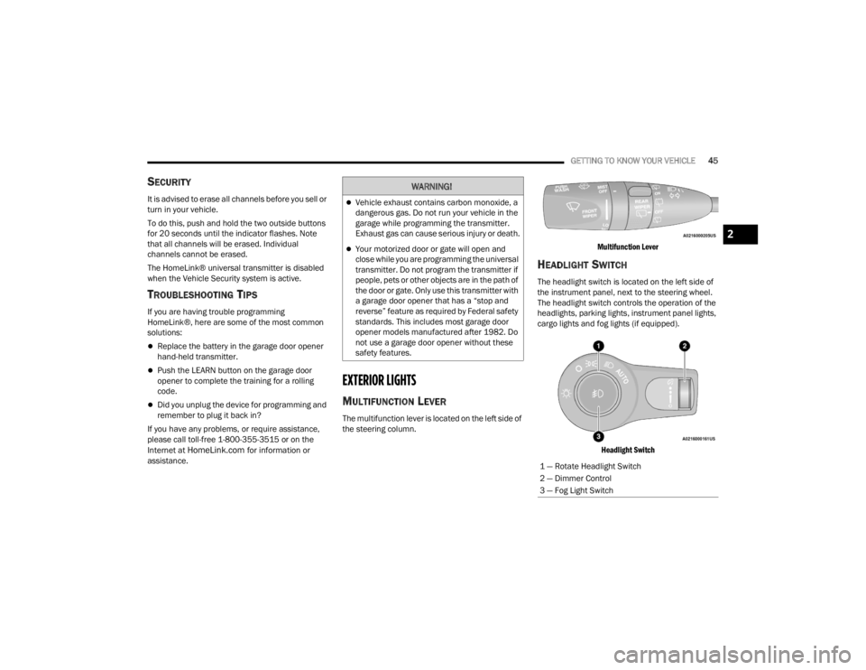
The headlight switch is located on the left side of
the instrument panel, next to the steering wheel.
The headlight switch controls the operation of the
headlights, parking lights, instrument panel lights,
cargo lights and fog lights (if equipped).
Headlight Switch
WARNING!
Vehicle exhaust contains carbon monoxide, a
dangerous gas. Do not run your vehicle in the
garage while programming the transmitter.
Exhaust gas can cause serious injury or death.
Your motorized door or gate will open and
close while you are programming the universal
transmitter. Do not program the transmitter if
people, pets or other objects are in the path of
the door or gate. Only use this transmitter with
a garage door opener that has a “stop and
reverse” feature as required by Federal safety
standards. This includes most garage door
opener models manufactured after 1982. Do
not use a garage door opener without these
safety features.
1 — Rotate Headlight Switch
2 — Dimmer Control
3 — Fog Light Switch
2
23_WD_OM_EN_USC_t.book Page 45
Page 48 of 328
46GETTING TO KNOW YOUR VEHICLE
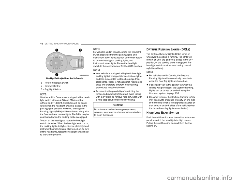
Headlight Switch (Vehicles Sold In Canada)
NOTE:Vehicles sold in Canada are equipped with a head -
light switch with an AUTO and ON detent but
without an OFF detent. Headlights will be deacti -
vated when the headlight switch is placed in the
parking lights position. However, the Daytime
Running Lights (DRLs) will be activated along with
the front and rear marker lights. The DRLs may be
deactivated when the parking brake is engaged.
To turn on the headlights, rotate the headlight
switch clockwise. When the headlight switch is on,
the parking lights, taillights, license plate light and
instrument panel lights are also turned on. To turn
off the headlights, rotate the headlight switch back
to the O (off) position.
NOTE:For vehicles sold in Canada, rotate the headlight
switch clockwise from the parking lights and
instrument panel lights position to the first detent
to turn on headlights, parking lights, and
instrument panel lights. Rotate the headlight
switch to the second detent for the AUTO position.
NOTE:
Your vehicle is equipped with plastic headlight
and fog light (if equipped) lenses that are lighter
and less susceptible to stone breakage than
glass lights. Plastic is not as scratch resistant as
glass and therefore different lens cleaning
procedures must be followed.
To minimize the possibility of scratching the
lenses and reducing light output, avoid wiping
with a dry cloth. To remove road dirt, wash with
a mild soap solution followed by rinsing.
DAYTIME RUNNING LIGHTS (DRLS)
The Daytime Running Lights (DRLs) come on
whenever the engine is running. The lights will
remain on until the ignition is placed in the OFF
position, or the parking brake is engaged. The
headlight switch must be used during normal
nighttime driving.
NOTE:
For vehicles sold in Canada, the Daytime
Running Lights will automatically deactivate
when the front fog lights are turned on.
If allowed by law in the country in which the
vehicle was purchased, the Daytime Running
Lights can be turned on and off using the
Uconnect system Ú page 153.
On some vehicles, the Daytime Running Lights
may deactivate or reduce intensity on one side
of the vehicle (when a turn signal is activated on
that side), or on both sides of the vehicle (when
the hazard warning lights are activated).
HIGH/LOW BEAM SWITCH
Push the multifunction lever toward the instrument
panel to switch the headlights to high beams.
Pulling the multifunction back will turn the low
beams on.
1 — Rotate Headlight Switch
2 — Dimmer Control
3 — Fog Light Switch
CAUTION!
Do not use abrasive cleaning components,
solvents, steel wool or other abrasive materials
to clean the lenses.
23_WD_OM_EN_USC_t.book Page 46
Page 69 of 328
GETTING TO KNOW YOUR VEHICLE67
(Continued)
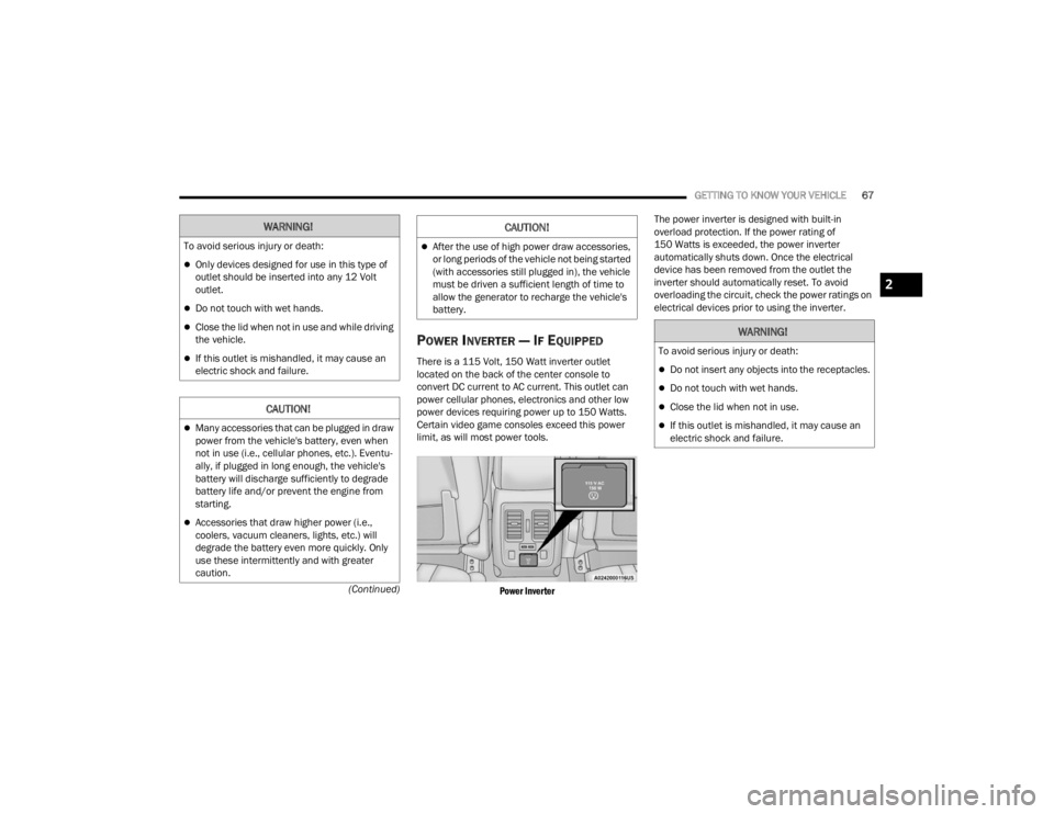
POWER INVERTER — IF EQUIPPED
There is a 115 Volt, 150 Watt inverter outlet
located on the back of the center console to
convert DC current to AC current. This outlet can
power cellular phones, electronics and other low
power devices requiring power up to 150 Watts.
Certain video game consoles exceed this power
limit, as will most power tools.
Power Inverter
The power inverter is designed with built-in
overload protection. If the power rating of
150 Watts is exceeded, the power inverter
automatically shuts down. Once the electrical
device has been removed from the outlet the
inverter should automatically reset. To avoid
overloading the circuit, check the power ratings on
electrical devices prior to using the inverter.
WARNING!
To avoid serious injury or death:
Only devices designed for use in this type of
outlet should be inserted into any 12 Volt
outlet.
Do not touch with wet hands.
Close the lid when not in use and while driving
the vehicle.
If this outlet is mishandled, it may cause an
electric shock and failure.
CAUTION!
Many accessories that can be plugged in draw
power from the vehicle's battery, even when
not in use (i.e., cellular phones, etc.). Eventu
-
ally, if plugged in long enough, the vehicle's
battery will discharge sufficiently to degrade
battery life and/or prevent the engine from
starting.
Accessories that draw higher power (i.e.,
coolers, vacuum cleaners, lights, etc.) will
degrade the battery even more quickly. Only
use these intermittently and with greater
caution.
After the use of high power draw accessories,
or long periods of the vehicle not being started
(with accessories still plugged in), the vehicle
must be driven a sufficient length of time to
allow the generator to recharge the vehicle's
battery.
CAUTION!
WARNING!
To avoid serious injury or death:
Do not insert any objects into the receptacles.
Do not touch with wet hands.
Close the lid when not in use.
If this outlet is mishandled, it may cause an
electric shock and failure.
2
23_WD_OM_EN_USC_t.book Page 67