audio DODGE DURANGO 2023 Owners Manual
[x] Cancel search | Manufacturer: DODGE, Model Year: 2023, Model line: DURANGO, Model: DODGE DURANGO 2023Pages: 328, PDF Size: 13.82 MB
Page 7 of 328
5
MULTIMEDIA
UCONNECT SYSTEMS ......................................... 153
CYBERSECURITY ................................................. 153
UCONNECT SETTINGS ......................................... 153Customer Programmable Features .............. 154
STEERING WHEEL AUDIO CONTROLS .............. 176
Radio Operation ............................................ 176
Media Mode................................................... 176
RADIO OPERATION AND MOBILE PHONES...... 176
Regulatory And Safety Information .............. 176
SAFETY
SAFETY FEATURES .............................................. 177 Anti-Lock Brake System (ABS) ..................... 177
Rear Seat Reminder Alert (RSRA) ................ 178
Electronic Brake Control (EBC) System ...... 178
AUXILIARY DRIVING SYSTEMS .......................... 183
Blind Spot Monitoring (BSM) —
If Equipped..................................................... 183
Forward Collision Warning (FCW) With
Mitigation ....................................................... 186
Tire Pressure Monitoring System (TPMS) .... 188
OCCUPANT RESTRAINT SYSTEMS .................... 191
Occupant Restraint Systems Features ........ 191
Important Safety Precautions....................... 191
Seat Belt Systems ........................................ 192
Supplemental Restraint Systems (SRS) ...... 198
Child Restraints ............................................. 210 SAFETY TIPS ....................................................... 225
Transporting Passengers .............................. 225Transporting Pets ......................................... 225
Connected Vehicles ...................................... 225
Safety Checks You Should Make Inside
The Vehicle ................................................... 226
Periodic Safety Checks You Should Make
Outside The Vehicle ...................................... 227
Exhaust Gas................................................... 228
Carbon Monoxide Warnings ......................... 228
IN CASE OF EMERGENCY
HAZARD WARNING FLASHERS ........................ 229
SOS AND ASSIST MIRROR — IF EQUIPPED ..... 229
JACKING AND TIRE CHANGING ........................ 232 Preparations For Jacking .............................. 232Jack Location ................................................. 233
Spare Tire Stowage ....................................... 234
Spare Tire Removal ....................................... 234
Jacking Instructions ..................................... 236
JUMP STARTING ................................................. 239
Preparations For Jump Start ........................ 240
Jump Starting Procedure .............................. 240
REFUELING IN EMERGENCY – IF EQUIPPED .. 242
IF YOUR ENGINE OVERHEATS ........................... 243
MANUAL PARK RELEASE ................................... 243
FREEING A STUCK VEHICLE .............................. 245
TOWING A DISABLED VEHICLE ........................ 246
Rear-Wheel Drive Models ............................. 247
All-Wheel Drive Models ................................. 247 ENHANCED ACCIDENT RESPONSE SYSTEM
(EARS) .................................................................. 248
EVENT DATA RECORDER (EDR) ......................... 248
SERVICING AND MAINTENANCE
SCHEDULED SERVICING .................................... 249
Maintenance Plan ......................................... 250
ENGINE COMPARTMENT .................................... 253
3.6L Engine ................................................... 253
5.7L Engine ................................................... 254
Checking Oil Level ......................................... 255
Adding Washer Fluid .................................... 255
Maintenance-Free Battery ........................... 255
Pressure Washing ......................................... 256
VEHICLE MAINTENANCE ..................................... 256
Engine Oil ...................................................... 256
Engine Oil Filter ............................................. 257Engine Air Cleaner Filter .............................. 257
Air Conditioner Maintenance ....................... 258
Accessory Drive Belt Inspection ................... 260Body Lubrication ........................................... 261
Windshield Wiper Blades.............................. 261
Exhaust System ............................................ 264
Cooling System.............................................. 265
Brake System ............................................... 268Automatic Transmission ............................... 269
Front/Rear Axle Fluid ................................... 269
Transfer Case ............................................... 270Fuses.............................................................. 270
Bulb Replacement ........................................ 278
23_WD_OM_EN_USC_t.book Page 5
Page 65 of 328
GETTING TO KNOW YOUR VEHICLE63
to be lowered below the Fold-Flat seat plane and
protects the armrest vinyl from damage when
using the vehicle to haul cargo.
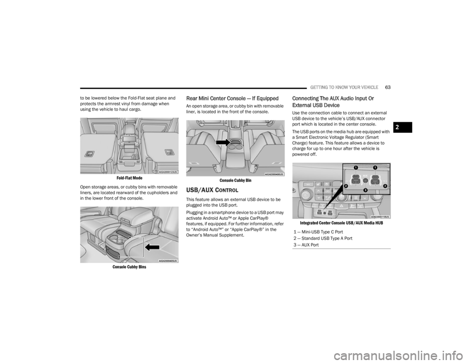
Fold-Flat Mode
Open storage areas, or cubby bins with removable
liners, are located rearward of the cupholders and
in the lower front of the console.
Console Cubby Bins
Rear Mini Center Console — If Equipped
An open storage area, or cubby bin with removable
liner, is located in the front of the console.
Console Cubby Bin
USB/AUX CONTROL
This feature allows an external USB device to be
plugged into the USB port.
Plugging in a smartphone device to a USB port may
activate Android Auto™ or Apple CarPlay®
features, if equipped. For further information, refer
to “Android Auto™” or “Apple CarPlay®” in the
Owner’s Manual Supplement.
Connecting The AUX Audio Input Or
External USB Device
Use the connection cable to connect an external
USB device to the vehicle’s USB/AUX connector
port which is located in the center console.
The USB ports on the media hub are equipped with
a Smart Electronic Voltage Regulator (Smart
Charge) feature. This feature allows a device to
charge for up to one hour after the vehicle is
powered off.
Integrated Center Console USB/AUX Media HUB
1 — Mini-USB Type C Port
2 — Standard USB Type A Port
3 — AUX Port
2
23_WD_OM_EN_USC_t.book Page 63
Page 66 of 328
64GETTING TO KNOW YOUR VEHICLE
Once the audio device is connected and
synchronized to the vehicle’s USB control system
(an external USB device may take a few minutes to
connect), the audio device starts charging and is
ready for use.
Once a device is connected to the USB port, it will
begin charging and is ready for use with the
system. Type C and Type A charge-only USB ports
can be used at the same time but cannot be used
simultaneously while playing media. When both
Type C and Type A charge-only USB ports are in use
they will be charged at a reduced rate.
NOTE:If the audio device battery is completely
discharged, it may not communicate with the USB
control system until a minimum charge is attained.
Leaving the audio device connected to the USB
control system may charge it to the required level.
Using This Feature
By using an external USB device to connect to the
USB port:
The audio device can be played on the vehicle’s
sound system, providing metadata (artist, track
title, album, etc.) information on the radio
display.
NOTE:Depending on track configuration, track infor -
mation may not be present on the radio display.
The audio device can be controlled using the
radio buttons to Play, Browse, and List the
contents.
The audio device battery charges when plugged
into the USB/AUX connector (if supported by the
specific audio device).
NOTE:For further information, refer to the Uconnect
Owner’s Manual Supplement.
Second Row USB Charging Port
Second Row USB Charging ports can be used for
charging purposes only. Use the connection cable
to connect an external USB device to the vehicle’s
USB charging ports which are located either on the
rear of the front center console and/or in the
second row center console.
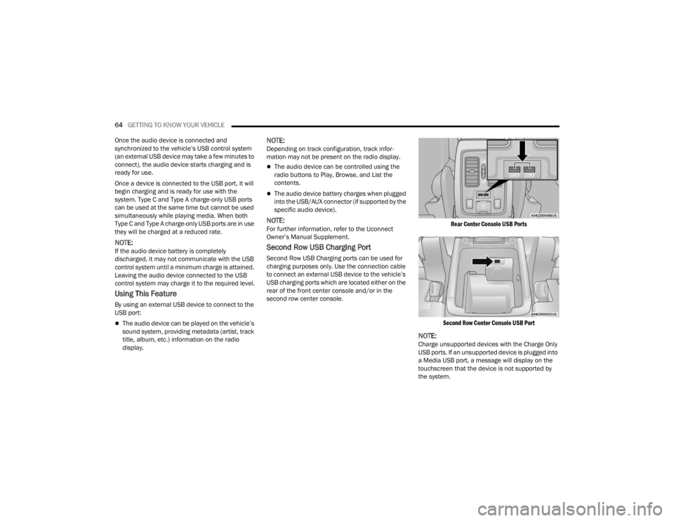
Rear Center Console USB Ports
Second Row Center Console USB Port
NOTE:Charge unsupported devices with the Charge Only
USB ports. If an unsupported device is plugged into
a Media USB port, a message will display on the
touchscreen that the device is not supported by
the system.
23_WD_OM_EN_USC_t.book Page 64
Page 88 of 328
86GETTING TO KNOW YOUR INSTRUMENT PANEL
Trailer Trip will display the following:
Distance
NOTE:Press and hold the OK button to reset all the infor -
mation.
Trailer Brake will display the following:
Output
Type
Gain
Audio
Push and release the up or down arrow
button until the Audio Menu icon/title is
highlighted in the instrument cluster display. This
menu will display the audio source information,
including the Song name, Artist name, and audio
source with an accompanying graphic.
Messages
Push and release the up or down arrow
button until the Messages Menu item is
highlighted. This feature shows the number of
stored warning messages. Pushing the left or
right arrow button will allow you to see what the
stored messages are.
When no messages are present, main menu icon
will be a closed envelope.
Screen Setup
Push and release the up or down arrow
button until the Screen Setup Menu icon/title is
highlighted in the instrument cluster display. Push
and release the OK button to enter the submenus
and follow the prompts on the screen as needed.
The Screen Setup feature allows you to change
what information is displayed in the instrument
cluster as well as the location that information is
displayed.
Current Gear
On
Off
Gear Display
Full
Single
NOTE:Menus with (show/hide) can push the OK button to
choose whether to show or hide this menu on the
instrument cluster display.
Defaults
Restore
Cancel
Upper Left or Upper Right
None Compass Outside Temp
Time Range To
Empty (RTE)Fuel Economy
Average
Fuel Economy
Current Trip A Trip B
Trailer Trip Gain
Favorite Menus
Speedometer Driver Assist
(Show/Hide)Stop/Start
Vehicle Info Fuel Economy
(Show/Hide)Trailer Tow –
If Equipped
(Show/Hide)
Performance –
If Equipped
(Show/Hide) Trip (Show/
Hide)
Audio (Show/
Hide)
Stored
Messages Screen Setup
23_WD_OM_EN_USC_t.book Page 86
Page 89 of 328
GETTING TO KNOW YOUR INSTRUMENT PANEL87
BATTERY SAVER ON/BATTERY SAVER
M
ODE MESSAGE — ELECTRICAL LOAD
R
EDUCTION ACTIONS — IF EQUIPPED
This vehicle is equipped with an Intelligent Battery
Sensor (IBS) to perform additional monitoring of
the electrical system and status of the vehicle
battery.
In cases when the IBS detects charging system
failure, or the vehicle battery conditions are
deteriorating, electrical load reduction actions will
take place to extend the driving time and distance
of the vehicle. This is done by reducing power to or
turning off non-essential electrical loads.
Load reduction is only active when the engine is
running. It will display a message if there is a risk
of battery depletion to the point where the vehicle
may stall due to lack of electrical supply, or will not
restart after the current drive cycle.
When load reduction is activated, the message
“Battery Saver On” or “Battery Saver Mode” will
appear in the instrument cluster.
These messages indicate the vehicle battery has a
low state of charge and continues to lose electrical
charge at a rate that the charging system cannot
sustain.
NOTE:
The charging system is independent from load
reduction. The charging system performs a diag -
nostic on the charging system continuously.
If the Battery Charge Warning Light is on it may
indicate a problem with the charging system
Ú page 89.
The electrical loads that may be switched off
(if equipped), and vehicle functions which can be
affected by load reduction:
Heated Seat/Vented Seats/Heated Wheel
Rear Defroster And Heated Mirrors
HVAC System
115 Volt AC Power Inverter System
Audio and Telematics System
Loss of the battery charge may indicate one or
more of the following conditions:
The charging system cannot deliver enough
electrical power to the vehicle system because
the electrical loads are larger than the capability
of the charging system. The charging system is
still functioning properly.
Turning on all possible vehicle electrical loads
(e.g. HVAC to max settings, exterior and interior
lights, overloaded power outlets +12 Volt,
115 Volt AC, USB ports) during certain driving
conditions (city driving, towing, frequent stop -
ping, etc.).
Installing options like additional lights, upfitter
electrical accessories, audio systems, alarms
and similar devices.
Unusual driving cycles (short trips separated by
long parking periods).
The vehicle was parked for an extended period
of time (weeks, months).
The battery was recently replaced and was not
charged completely.
The battery was discharged by an electrical load
left on when the vehicle was parked.
The battery was used for an extended period
with the engine not running to supply radio,
lights, chargers, +12 Volt portable appliances
like vacuum cleaners, game consoles and
similar devices.
3
23_WD_OM_EN_USC_t.book Page 87
Page 90 of 328
88GETTING TO KNOW YOUR INSTRUMENT PANEL
What to do when an electrical load reduction
action message is present (“Battery Saver On” or
“Battery Saver Mode”)
During a trip:
Reduce power to unnecessary loads if possible:
Turn off redundant lights (interior or exte -
rior)
Check what may be plugged in to power
outlets +12 Volt, 115 Volt AC, USB ports
Check HVAC settings (blower, temperature)
Check the audio settings (volume)
After a trip:
Check if any aftermarket equipment was
installed (additional lights, upfitter electrical
accessories, audio systems, alarms) and review
specifications if any (load and Ignition Off Draw
currents).
Evaluate the latest driving cycles (distance,
driving time and parking time).
The vehicle should have service performed if
the message is still present during consecutive
trips, and if the evaluation and driving pattern of
the vehicle did not help to identify the cause.
WARNING LIGHTS AND MESSAGES
The warning/indicator lights will illuminate in the
instrument panel together with a dedicated
message and/or acoustic signal when applicable.
These indications are indicative and precautionary
and as such must not be considered as exhaustive
and/or alternative to the information contained in
the Owner’s Manual, which you are advised to read
carefully in all cases. Always refer to the
information in this chapter in the event of a failure
indication. All active telltales will display first if
applicable. The system check menu may appear
different based upon equipment options and
current vehicle status. Some telltales are optional
and may not appear.
RED WARNING LIGHTS
Seat Belt Reminder Warning Light
This warning light indicates when the
driver or passenger seat belt is
unbuckled. When the ignition is first
placed in the ON/RUN or ACC/ON/RUN
position and if the driver’s seat belt is unbuckled,
a chime will sound and the light will turn on. When
driving, if the driver or front passenger seat belt
remains unbuckled, the Seat Belt Reminder Light
will flash or remain on continuously and a chime
will sound Ú page 191.
Air Bag Warning Light
This warning light will illuminate to
indicate a fault with the air bag, and will
turn on for four to eight seconds as a bulb
check when the ignition is placed in the
ON/RUN or ACC/ON/RUN position. This light will
illuminate with a single chime when a fault with the
air bag has been detected, it will stay on until the
fault is cleared. If the light is either not on during
startup, stays on, or turns on while driving, have
the system inspected at an authorized dealer as
soon as possible.
Brake Warning Light
This warning light monitors various brake
functions, including brake fluid level and
parking brake application. If the brake
light turns on it may indicate that the
parking brake is applied, that the brake fluid level
is low, or that there is a problem with the Anti-Lock
Brake System reservoir.
If the light remains on when the parking brake has
been disengaged, and the fluid level is at the full
mark on the master cylinder reservoir, it indicates
a possible brake hydraulic system malfunction or
that a problem with the Brake Booster has been
detected by the Anti-Lock Brake System (ABS) /
Electronic Stability Control (ESC) system. In this
case, the light will remain on until the condition has
been corrected. If the problem is related to the
brake booster, the ABS pump will run when
23_WD_OM_EN_USC_t.book Page 88
Page 131 of 328
STARTING AND OPERATING129
NOTE:If the radio is on, ParkSense will reduce the volume
of the radio when the system is sounding an audio
tone.
Front Park Assist Audible Alerts
ParkSense will turn off the Front Park Assist
audible alert (chime) after approximately three
seconds when an obstacle has been detected, the
vehicle is stationary, and brake pedal is applied.
Adjustable Chime Volume Settings
Front and Rear chime volume settings can be
selected from the Uconnect system
Úpage 153.
The chime volume settings include low,
medium, and high.
ParkSense will retain its last known configura -
tion state through ignition cycles.
PARKSENSE WARNING DISPLAY
The ParkSense Warning screen is located within
the instrument cluster display Ú page 79. It
provides visual warnings to indicate the distance
between the rear fascia/bumper and/or front
fascia/bumper and the detected obstacle.
The ParkSense Warning screen will only be
displayed if Sound and Display is selected from the
Customer Programmable Features section of the
Uconnect system Ú page 153.
ENABLING AND DISABLING PARKSENSE
ParkSense can be enabled and disabled
with the ParkSense switch.
When the ParkSense switch is pressed to
disable the system, the LED light on the switch will
be illuminated.
When the ParkSense switch is pushed to disable
the system, the instrument cluster will display the
“PARKSENSE OFF” message for approximately five
seconds. When the gear selector is moved to
REVERSE and the system is disabled, the
instrument cluster display will display the
“PARKSENSE OFF” message for as long as the
vehicle is in REVERSE.
NOTE:When ParkSense is disabled and the gear selector
is moved to the DRIVE position, no warning
message will be displayed.
The ParkSense switch LED will be on when
ParkSense is disabled or requires service. The
ParkSense switch LED will be off when the system
is enabled. When the system is disabled due to a
fault, the LED light on the switch will be
illuminated. If the driver tries to press the
ParkSense switch to activate the system, the
button will blink for five seconds to show the
request was received, but cannot be fulfilled.
OPERATION WITH A TRAILER
For vehicles equipped with an Integrated Trailer
Brake Module (ITBM), the operation of the rear
sensors is automatically deactivated when the
trailer's electric plug is inserted in the vehicle's tow
hook socket. The front system is still functional,
and the arcs will be overlaid with a “Trailer”
message. The rear sensors are automatically
reactivated when the trailer's cable plug is
removed.
When the vehicle is connected to a trailer, the
instrument cluster display will show the "Rear
ParkSense Unavailable Trailer Connected"
message in the following situations:
For five seconds at vehicle start up
For five seconds when the ParkSense button is
pushed, as long as an object is not detected in
the front
As long as the vehicle is in REVERSE (vehicle
graphic displayed with a trailer overlay)
NOTE:
For more information on the Integrated Trailer
Brake Module, see Ú page 142.
For vehicles not equipped with ITBM, the
automatic braking may falsely be applied if a trailer
is hooked up, and Park Assist is not manually
deactivated. It is also possible, the trailer may be
mistaken as a close object.
4
23_WD_OM_EN_USC_t.book Page 129
Page 161 of 328
MULTIMEDIA159
New Text Message Pop-Ups This setting will allow you to have pop-up notifications for new text messages.
This setting options are “On” and “Off”.
Missed Calls Message This setting will allow you to have pop-up notifications for missed calls. This
setting options are “On” and “Off”.
Personal Settings Linked to Key Fob This setting will recall preset radio stations and driver seat position that have
been linked to the key fob.
Navigation Pop-Ups This setting will allow you to have pop-up notifications for Navigation. This
setting options are “On” and “Off”.
Navigation Settings This setting will direct you to the Navigation settings within Navigation Mode.
Auto-On Driver Heated/Ventilated Seat & Heated Steering Wheel With Vehicle Start This setting will activate the vehicle’s comfort systems and heated seats or
heated steering wheel when the vehicle is remote started or ignition is
started. The “Off” setting will not activate the comfort systems. The “Remote
Start” setting will only activate the comfort systems when using Remote Start.
The “All Start” setting will activate the comfort systems whenever the vehicle
is started.
Audio Settings This setting will take you to the Audio settings for the vehicle profiles.
Reset App Drawer to Default Order This setting will reset the app drawer to its factory default layout.
Restore Settings to Default This setting will return all the previously changed settings to their factory
defaults.
More Profile Options This setting will give access to more profile options.
Setting Name Description
5
23_WD_OM_EN_USC_t.book Page 159
Page 166 of 328
164MULTIMEDIA
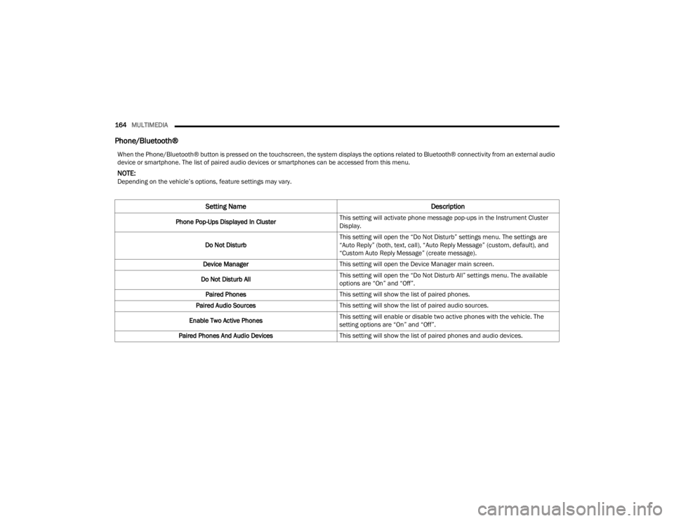
Phone/Bluetooth®
When the Phone/Bluetooth® button is pressed on the touchscreen, the system displays the options related to Bluetooth® connectivity from an external audio
device or smartphone. The list of paired audio devices or smartphones can be accessed from this menu.
NOTE:Depending on the vehicle’s options, feature settings may vary.
Setting Name Description
Phone Pop-Ups Displayed In ClusterThis setting will activate phone message pop-ups in the Instrument Cluster
Display.
Do Not Disturb This setting will open the “Do Not Disturb” settings menu. The settings are
“Auto Reply” (both, text, call), “Auto Reply Message” (custom, default), and
“Custom Auto Reply Message” (create message).
Device Manager This setting will open the Device Manager main screen.
Do Not Disturb All This setting will open the “Do Not Disturb All” settings menu. The available
options are “On” and “Off”.
Paired Phones This setting will show the list of paired phones.
Paired Audio Sources This setting will show the list of paired audio sources.
Enable Two Active Phones This setting will enable or disable two active phones with the vehicle. The
setting options are “On” and “Off”.
Paired Phones And Audio Devices This setting will show the list of paired phones and audio devices.
23_WD_OM_EN_USC_t.book Page 164
Page 167 of 328
MULTIMEDIA165
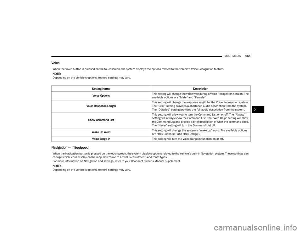
Voice
Navigation — If Equipped
When the Voice button is pressed on the touchscreen, the system displays the options related to the vehicle’s Voice Recognition feature.
NOTE:Depending on the vehicle’s options, feature settings may vary.
Setting Name Description
Voice OptionsThis setting will change the voice type during a Voice Recognition session. The
available options are “Male” and “Female”.
Voice Response Length This setting will change the response length for the Voice Recognition system.
The “Brief” setting provides a shortened audio description from the system.
The “Detailed” setting provides the full audio description from the system.
Show Command List This setting will allow you to turn the Command List on or off. The “Always”
setting will always show the Command List. The “With Help” setting will show
the Command List and provide a brief description of what the command does.
The “Never” setting will turn the Command List off.
Wake Up Word This setting will change the system’s “Wake Up” word. The available options
are “Hey Uconnect” and “Hey Dodge”.
Voice Barge-in This setting will turn the Voice Barge-in function on or off.
When the Navigation button is pressed on the touchscreen, the system displays options related to the vehicle’s built-in Navigation system. These settings can
change which icons display on the map, how “time to arrival is calculated”, and route types.
For more information on Navigation and settings, refer to your Uconnect Owner’s Manual Supplement.
NOTE:Depending on the vehicle’s options, feature settings may vary.
5
23_WD_OM_EN_USC_t.book Page 165