tow DODGE DURANGO SRT 2018 Repair Manual
[x] Cancel search | Manufacturer: DODGE, Model Year: 2018, Model line: DURANGO SRT, Model: DODGE DURANGO SRT 2018Pages: 568, PDF Size: 6.54 MB
Page 369 of 568
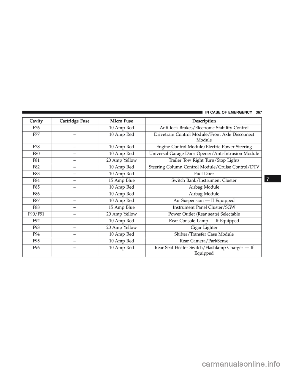
Cavity Cartridge Fuse Micro FuseDescription
F76 –10 Amp Red Anti-lock Brakes/Electronic Stability Control
F77 –10 Amp Red Drivetrain Control Module/Front Axle Disconnect
Module
F78 –10 Amp Red Engine Control Module/Electric Power Steering
F80 –10 Amp Red Universal Garage Door Opener/Anti-Intrusion Module
F81 –20 Amp Yellow Trailer Tow Right Turn/Stop Lights
F82 –10 Amp Red Steering Column Control Module/Cruise Control/DTV
F83 –10 Amp Red Fuel Door
F84 –15 Amp Blue Switch Bank/Instrument Cluster
F85 –10 Amp Red Airbag Module
F86 –10 Amp Red Airbag Module
F87 –10 Amp Red Air Suspension — If Equipped
F88 –15 Amp Blue Instrument Panel Cluster/SGW
F90/F91 –20 Amp Yellow Power Outlet (Rear seats) Selectable
F92 –10 Amp Red Rear Console Lamp — If Equipped
F93 –20 Amp Yellow Cigar Lighter
F94 –10 Amp Red Shifter/Transfer Case Module
F95 –10 Amp Red Rear Camera/ParkSense
F96 –10 Amp Red Rear Seat Heater Switch/Flashlamp Charger — If
Equipped
7
IN CASE OF EMERGENCY 367
Page 372 of 568
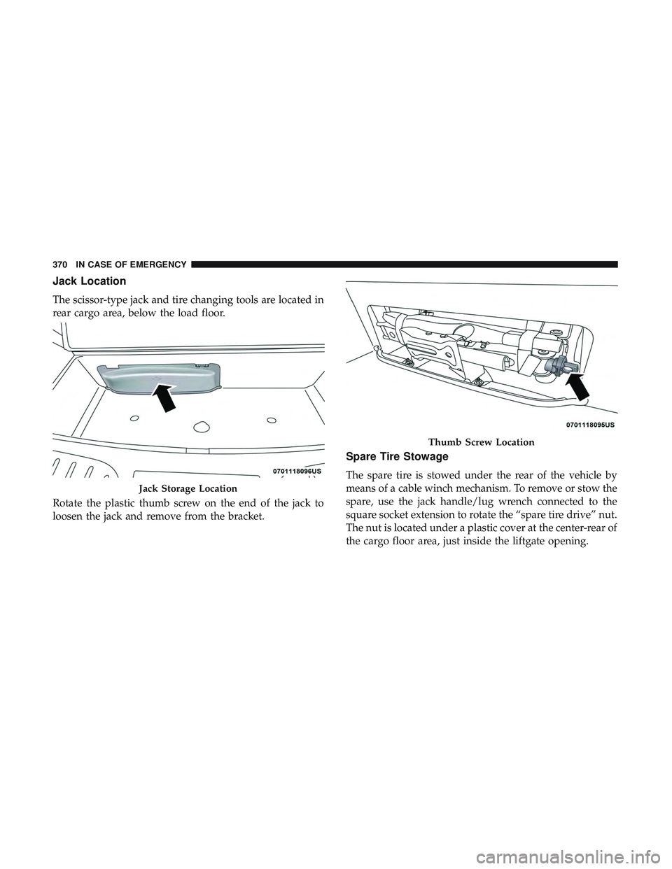
Jack Location
The scissor-type jack and tire changing tools are located in
rear cargo area, below the load floor.
Rotate the plastic thumb screw on the end of the jack to
loosen the jack and remove from the bracket.
Spare Tire Stowage
The spare tire is stowed under the rear of the vehicle by
means of a cable winch mechanism. To remove or stow the
spare, use the jack handle/lug wrench connected to the
square socket extension to rotate the “spare tire drive” nut.
The nut is located under a plastic cover at the center-rear of
the cargo floor area, just inside the liftgate opening.
Jack Storage Location
Thumb Screw Location
370 IN CASE OF EMERGENCY
Page 374 of 568
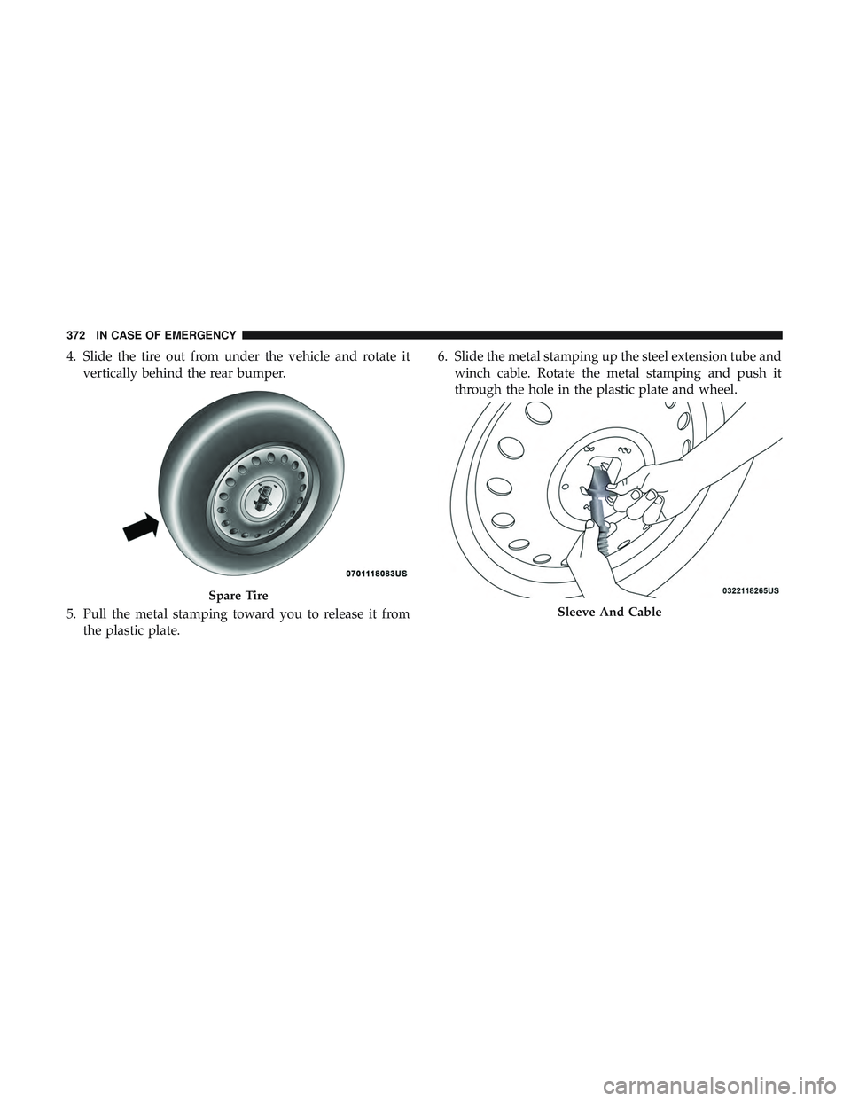
4. Slide the tire out from under the vehicle and rotate itvertically behind the rear bumper.
5. Pull the metal stamping toward you to release it from the plastic plate. 6. Slide the metal stamping up the steel extension tube and
winch cable. Rotate the metal stamping and push it
through the hole in the plastic plate and wheel.
Spare Tire
Sleeve And Cable
372 IN CASE OF EMERGENCY
Page 376 of 568
Jacking Instructions
WARNING!
Carefully follow these tire changing warnings to help
prevent personal injury or damage to your vehicle:
•
Always park on a firm, level surface as far from the edge
of the roadway as possible before raising the vehicle.
•Turn on the Hazard Warning flasher.
• Block the wheel diagonally opposite the wheel to be
raised.
• Apply the parking brake firmly and set the transmis-
sion in PARK.
• Never start or run the engine with the vehicle on a
jack.
• Do not let anyone sit in the vehicle when it is on a
jack.
• Do not get under the vehicle when it is on a jack. If
you need to get under a raised vehicle, take it to a
service center where it can be raised on a lift.
• Only use the jack in the positions indicated and for
lifting this vehicle during a tire change.
• If working on or near a roadway, be extremely
careful of motor traffic.
(Continued)
WARNING! (Continued)
•To assure that spare tires, flat or inflated, are securely
stowed, spares must be stowed with the valve stem
facing the ground.
CAUTION!
Do not attempt to raise the vehicle by jacking on
locations other than those indicated in the Jacking
Instructions for this vehicle.
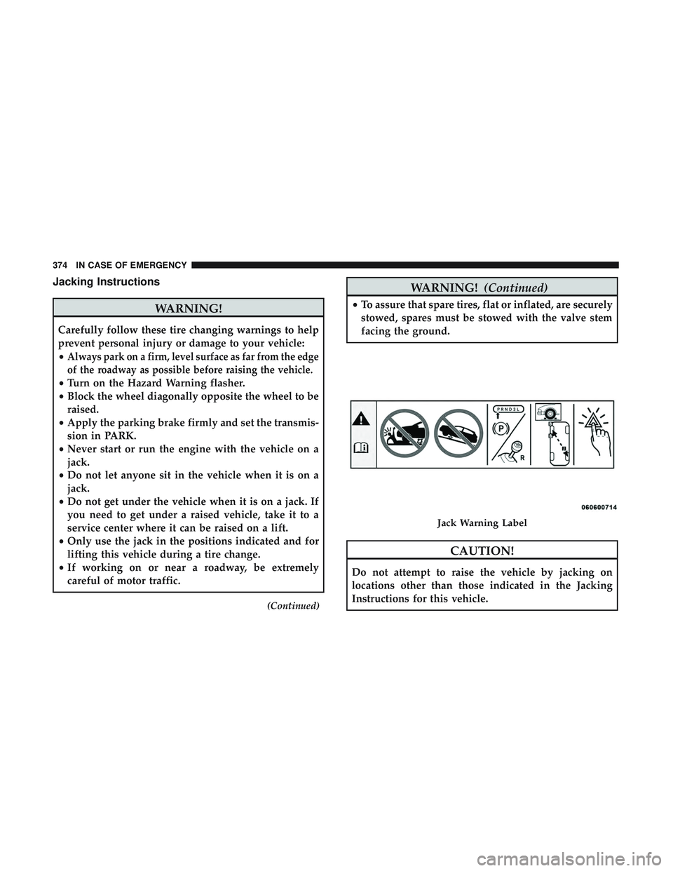
Jack Warning Label
374 IN CASE OF EMERGENCY
Page 378 of 568
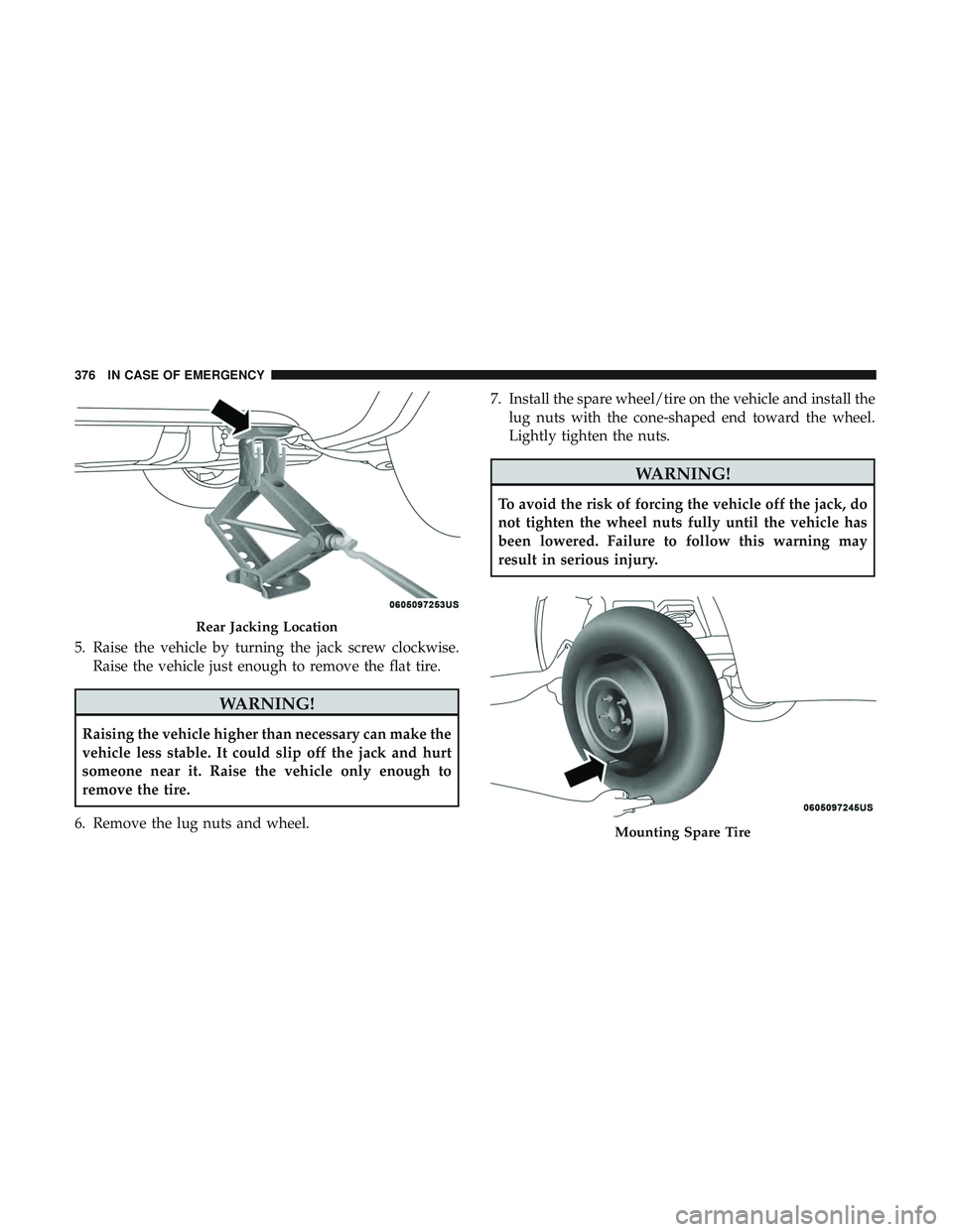
5. Raise the vehicle by turning the jack screw clockwise.Raise the vehicle just enough to remove the flat tire.
WARNING!
Raising the vehicle higher than necessary can make the
vehicle less stable. It could slip off the jack and hurt
someone near it. Raise the vehicle only enough to
remove the tire.
6. Remove the lug nuts and wheel. 7. Install the spare wheel/tire on the vehicle and install the
lug nuts with the cone-shaped end toward the wheel.
Lightly tighten the nuts.
WARNING!
To avoid the risk of forcing the vehicle off the jack, do
not tighten the wheel nuts fully until the vehicle has
been lowered. Failure to follow this warning may
result in serious injury.
Rear Jacking Location
Mounting Spare Tire
376 IN CASE OF EMERGENCY
Page 381 of 568
13. Lower the jack to the fully closed position. Return thetools to the proper positions in the tool bag. Fold the
flap on the tool bag under the tools and roll the tools in
the bag underneath the others. Use the hook and loop
fasteners to secure the tool bag to the jack with the lug
wrench on the forward side of the jack. Expand the jack
on the bracket by turning the thumb screw clockwise
until it is tight to prevent rattles.
14. Reinstall the plastic plug into the floor of the cargo area. Roll up and store the Jack, Tool Kit and Tire
Changing Instructions. Reinstall the cover for the jack
in the rear storage bin.
15. Have the aluminum road wheel and tire repaired as soon as possible and properly secure the spare tire, jack
and tool kit.
WARNING!
A loose tire or jack thrown forward in a collision or
hard stop, could endanger the occupants of the vehicle.
Always stow the jack parts and the spare tire in the
places provided.
Road Tire Installation
1. Mount the road tire on the axle.
2. Install the remaining lug nuts with the cone shaped endof the nut toward the wheel. Lightly tighten the lug
nuts.
WARNING!
To avoid the risk of forcing the vehicle off the jack, do
not tighten the wheel nuts fully until the vehicle has
been lowered. Failure to follow this warning may
result in serious injury.
3. Lower the vehicle to the ground by turning the jack handle counterclockwise.
4. Refer to “Torque Specifications” in “Technical Specifica- tions” for proper lug nut torque.
5. After 25 miles (40 km), check the lug nut torque with a torque wrench to ensure that all lug nuts are properly
seated against the wheel.
7
IN CASE OF EMERGENCY 379
Page 386 of 568
CAUTION!
Driving with a hot cooling system could damage your
vehicle. If the temperature gauge reads HOT (H), pull
over and stop the vehicle. Idle the vehicle with the air
conditioner turned off until the pointer drops back
into the normal range. If the pointer remains on HOT
(H), and you hear continuous chimes, turn the engine
off immediately and call for service.
MANUAL PARK RELEASE
WARNING!
Always secure your vehicle by fully applying the
parking brake before activating the Manual Park Re-
lease. In addition, you should be seated in the driver ’s
seat with your foot firmly on the brake pedal when
activating the Manual Park Release. Activating the
Manual Park Release will allow your vehicle to roll
away if it is not secured by the parking brake, or by
proper connection to a tow vehicle. Activating the
Manual Park Release on an unsecured vehicle could
lead to serious injury or death for those in or around
the vehicle.In order to move the vehicle in cases where the transmis-
sion will not shift out of PARK (such as a dead battery), a
Manual Park Release is available.
Follow these steps to use the Manual Park Release:
1. Firmly apply the parking brake.
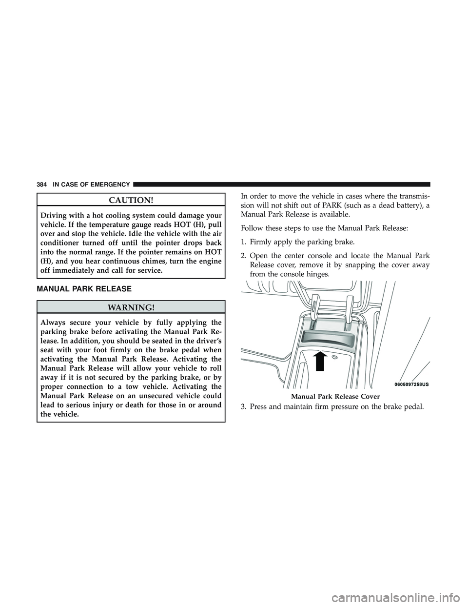
2. Open the center console and locate the Manual Park
Release cover, remove it by snapping the cover away
from the console hinges.
3. Press and maintain firm pressure on the brake pedal.
Manual Park Release Cover
384 IN CASE OF EMERGENCY
Page 387 of 568
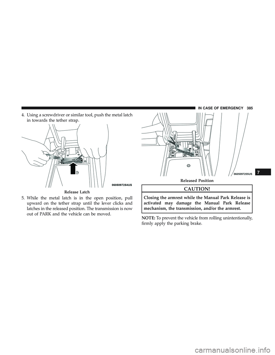
4. Using a screwdriver or similar tool, push the metal latchin towards the tether strap.
5. While the metal latch is in the open position, pull upward on the tether strap until the lever clicks and
latches in the released position. The transmission is now
out of PARK and the vehicle can be moved.
CAUTION!
Closing the armrest while the Manual Park Release is
activated may damage the Manual Park Release
mechanism, the transmission, and/or the armrest.
NOTE: To prevent the vehicle from rolling unintentionally,
firmly apply the parking brake.
Release Latch
Released Position
7
IN CASE OF EMERGENCY 385
Page 388 of 568
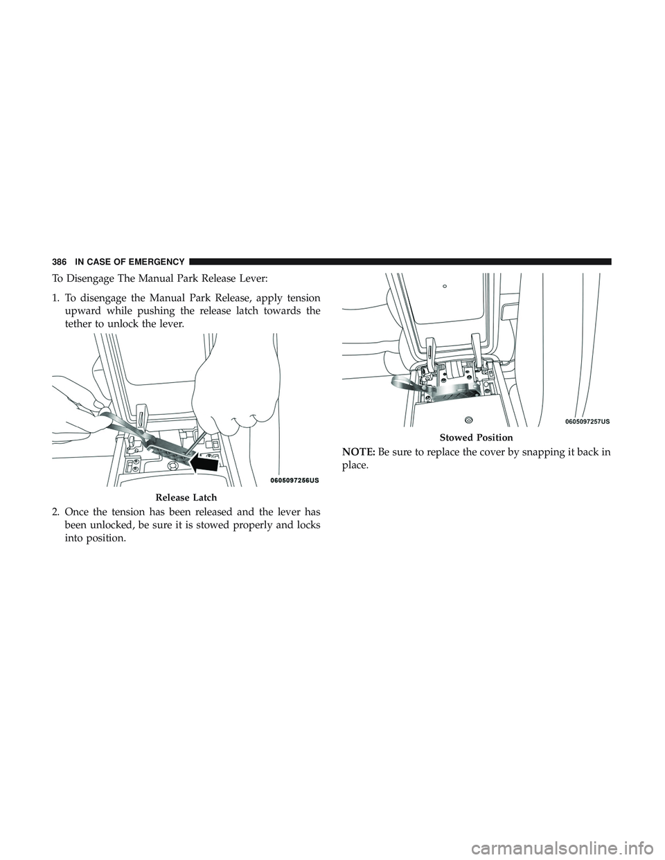
To Disengage The Manual Park Release Lever:
1. To disengage the Manual Park Release, apply tensionupward while pushing the release latch towards the
tether to unlock the lever.
2. Once the tension has been released and the lever has been unlocked, be sure it is stowed properly and locks
into position. NOTE:
Be sure to replace the cover by snapping it back in
place.
Release Latch
Stowed Position
386 IN CASE OF EMERGENCY
Page 390 of 568
CAUTION!(Continued)
•Revving the engine or spinning the wheels too fast
may lead to transmission overheating and failure. It
can also damage the tires. Do not spin the wheels
above 30 mph (48 km/h) while in gear (no transmis-
sion shifting occurring).
TOWING A DISABLED VEHICLE
The manufacturer requires towing your vehicle with all
four wheels OFFthe ground using a flatbed.
If the key fob is unavailable, or the vehicle’s battery is
discharged, refer to “Manual Park Release” in this section
for instructions on shifting the transmission out of PARK
for loading onto a flatbed truck.
CAUTION!
• Towing this vehicle using any other method can
cause severe transmission and/or transfer case dam-
age.
• Damage from improper towing is not covered under
the New Vehicle Limited Warranty.
ENHANCED ACCIDENT RESPONSE SYSTEM
(EARS)
This vehicle is equipped with an Enhanced Accident
Response System.
Please refer to “Occupant Restraint Systems” in “Safety”
for further information on the Enhanced Accident Re-
sponse System (EARS) function.
EVENT DATA RECORDER (EDR)
This vehicle is equipped with an Event Data Recorder
(EDR). The main purpose of an EDR is to record data that
will assist in understanding how a vehicle’s systems per-
formed under certain crash or near crash-like situations,
such as an air bag deployment or hitting a road obstacle.
Please refer to “Occupant Restraint Systems” in “Safety”
for further information on the Event Data Recorder (EDR).
388 IN CASE OF EMERGENCY