tow DODGE DURANGO SRT 2019 Manual Online
[x] Cancel search | Manufacturer: DODGE, Model Year: 2019, Model line: DURANGO SRT, Model: DODGE DURANGO SRT 2019Pages: 572, PDF Size: 6.59 MB
Page 390 of 572
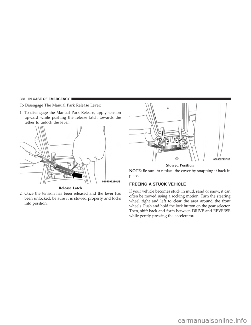
To Disengage The Manual Park Release Lever:
1. To disengage the Manual Park Release, apply tensionupward while pushing the release latch towards the
tether to unlock the lever.
2. Once the tension has been released and the lever has been unlocked, be sure it is stowed properly and locks
into position. NOTE:
Be sure to replace the cover by snapping it back in
place.
FREEING A STUCK VEHICLE
If your vehicle becomes stuck in mud, sand or snow, it can
often be moved using a rocking motion. Turn the steering
wheel right and left to clear the area around the front
wheels. Push and hold the lock button on the gear selector.
Then, shift back and forth between DRIVE and REVERSE
while gently pressing the accelerator.Release Latch
Stowed Position
388 IN CASE OF EMERGENCY
Page 392 of 572
TOWING A DISABLED VEHICLE
The manufacturer requires towing your vehicle with all
four wheelsOFFthe ground using a flatbed.
If the key fob is unavailable, or the vehicle’s battery is
discharged, refer to “Manual Park Release” in this section
for instructions on shifting the transmission out of PARK
for loading onto a flatbed truck.
CAUTION!
• Towing this vehicle using any other method can
cause severe transmission and/or transfer case dam-
age.
• Damage from improper towing is not covered under
the New Vehicle Limited Warranty.
ENHANCED ACCIDENT RESPONSE SYSTEM
(EARS)
This vehicle is equipped with an Enhanced Accident
Response System.
Please refer to “Occupant Restraint Systems” in “Safety”
for further information on the Enhanced Accident Re-
sponse System (EARS) function.
EVENT DATA RECORDER (EDR)
This vehicle is equipped with an Event Data Recorder
(EDR). The main purpose of an EDR is to record data that
will assist in understanding how a vehicle’s systems per-
formed under certain crash or near crash-like situations,
such as an air bag deployment or hitting a road obstacle.
Please refer to “Occupant Restraint Systems” in “Safety”
for further information on the Event Data Recorder (EDR).
390 IN CASE OF EMERGENCY
Page 398 of 572
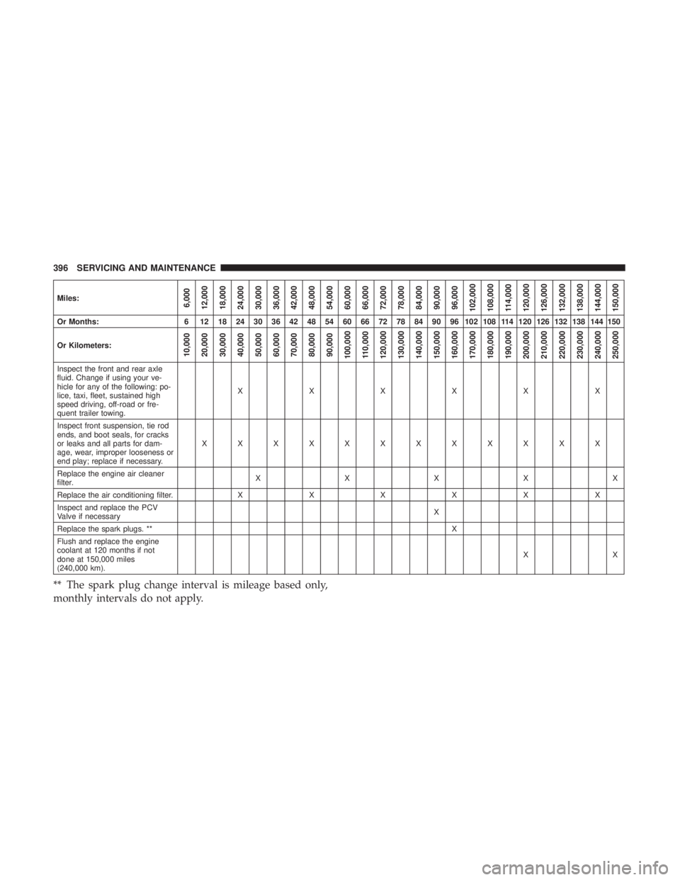
Miles:6,000
12,000
18,000
24,000
30,000
36,000
42,000
48,000
54,000
60,000
66,000
72,000
78,000
84,000
90,000
96,000
102,000
108,000 114,000
120,000
126,000
132,000
138,000
144,000
150,000
Or Months: 6 12 18 24 30 36 42 48 54 60 66 72 78 84 90 96 102 108 114 120 126 132 138 144 150
Or Kilometers:
10,000
20,000
30,000
40,000
50,000
60,000
70,000
80,000
90,000
100,000
110,000
120,000
130,000
140,000
150,000
160,000
170,000
180,000
190,000
200,000
210,000
220,000
230,000
240,000
250,000
Inspect the front and rear axle
fluid. Change if using your ve-
hicle for any of the following: po-
lice, taxi, fleet, sustained high
speed driving, off-road or fre-
quent trailer towing. XXXXXX
Inspect front suspension, tie rod
ends, and boot seals, for cracks
or leaks and all parts for dam-
age, wear, improper looseness or
end play; replace if necessary. XXXXXXXXXXXX
Replace the engine air cleaner
filter. XXXXX
Replace the air conditioning filter. XXX XX X
Inspect and replace the PCV
Valve if necessary X
Replace the spark plugs. ** X
Flush and replace the engine
coolant at 120 months if not
done at 150,000 miles
(240,000 km). XX
** The spark plug change interval is mileage based only,
monthly intervals do not apply.
396 SERVICING AND MAINTENANCE
Page 401 of 572
Checking Oil Level
To assure proper lubrication of your vehicle’s engine, the
engine oil must be maintained at the correct level. Check
the oil level at regular intervals, such as every fuel stop.
The best time to check the engine oil level is about five
minutes after a fully warmed up engine is shut off.
Checking the oil while the vehicle is on level ground will
improve the accuracy of the oil level readings. Always
maintain the oil level within the SAFE zone on the dipstick.
Adding one quart of oil when the reading is at the bottom
of the SAFE zone will result in a reading at the top of the
safe zone on these engines.
CAUTION!
Overfilling or underfilling will cause oil aeration or
loss of oil pressure. This could damage your engine.
Adding Washer Fluid
The instrument cluster display will indicate when the
washer fluid level is low. When the sensor detects a low
fluid level, the windshield will light on the vehicle graphic
outline and the “WASHER FLUID LOW” message will be
displayed.The fluid reservoir for the windshield washers and the rear
window washer is shared. The fluid reservoir is located in
the engine compartment, be sure to check the fluid level at
regular intervals. Fill the reservoir with windshield washer
solvent only (not radiator antifreeze). When refilling the
washer fluid reservoir, take some washer fluid and apply it
to a cloth or towel and wipe clean the wiper blades, this
will help blade performance. To prevent freeze-up of your
windshield washer system in cold weather, select a solu-
tion or mixture that meets or exceeds the temperature
range of your climate. This rating information can be found
on most washer fluid containers.
WARNING!
Commercially available windshield washer solvents
are flammable. They could ignite and burn you. Care
must be exercised when filling or working around the
washer solution.
Maintenance-Free Battery
Your vehicle is equipped with a maintenance-free battery.
You will never have to add water, nor is periodic mainte-
nance required.
8
SERVICING AND MAINTENANCE 399
Page 407 of 572
Air Conditioning Filter Replacement (A/C Air Filter)
Refer to “Scheduled Servicing” in this section for the
proper maintenance intervals.
WARNING!
Do not remove the cabin air filter while the vehicle is
running, or while the ignition is in the ACC or ON/
RUN mode. With the cabin air filter removed and the
blower operating, the blower can contact hands and
may propel dirt and debris into your eyes, resulting in
personal injury.
The A/C air filter is located in the fresh air inlet behind the
glove compartment. Perform the following procedure to
replace the filter:
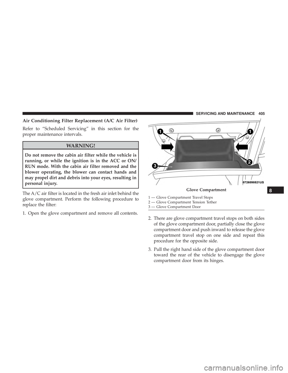
1. Open the glove compartment and remove all contents. 2. There are glove compartment travel stops on both sides
of the glove compartment door, partially close the glove
compartment door and push inward to release the glove
compartment travel stop on one side and repeat this
procedure for the opposite side.
3. Pull the right hand side of the glove compartment door toward the rear of the vehicle to disengage the glove
compartment door from its hinges.
Glove Compartment
1 — Glove Compartment Travel Stops
2 — Glove Compartment Tension Tether
3 — Glove Compartment Door
8
SERVICING AND MAINTENANCE 405
Page 408 of 572
NOTE:When disengaging the glove compartment door
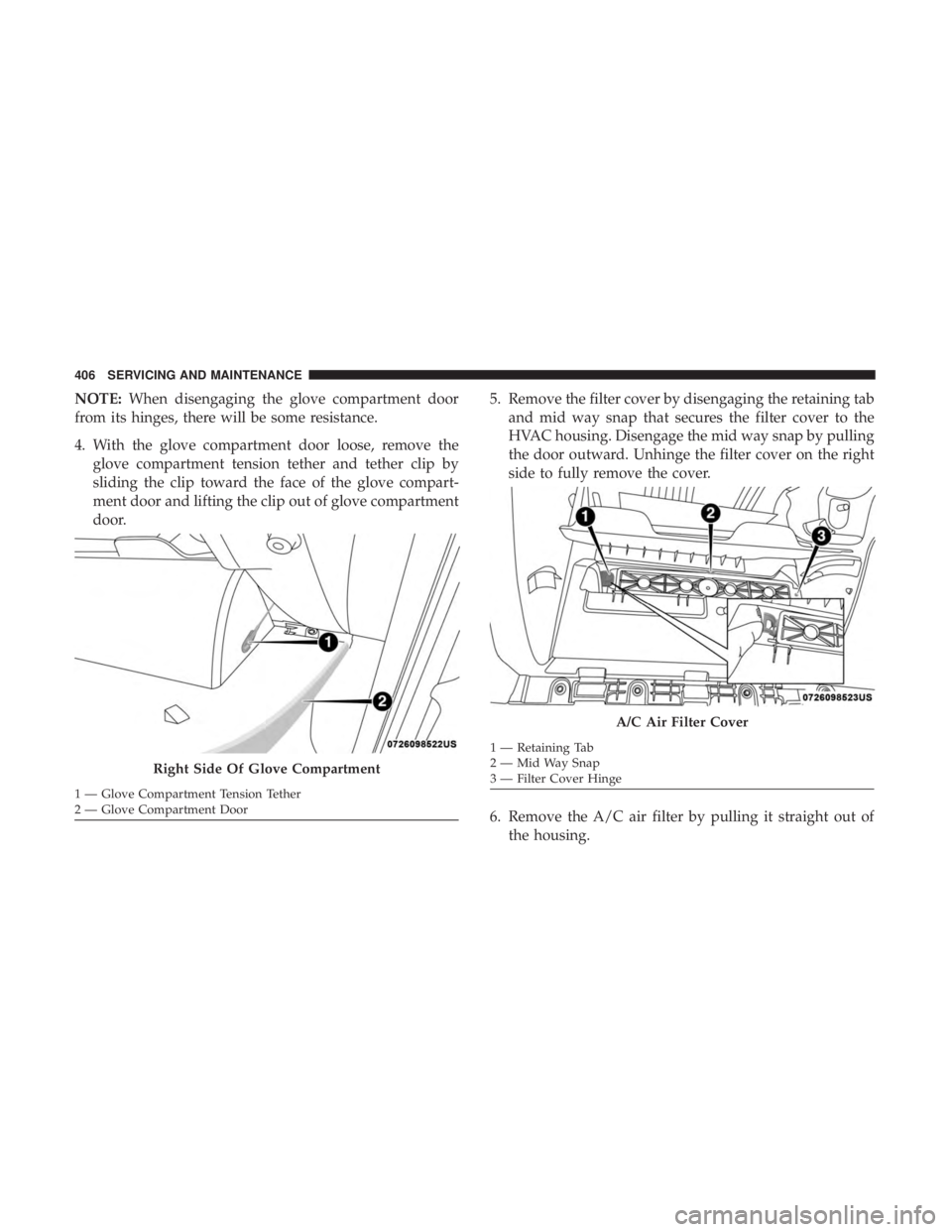
from its hinges, there will be some resistance.
4. With the glove compartment door loose, remove the glove compartment tension tether and tether clip by
sliding the clip toward the face of the glove compart-
ment door and lifting the clip out of glove compartment
door. 5. Remove the filter cover by disengaging the retaining tab
and mid way snap that secures the filter cover to the
HVAC housing. Disengage the mid way snap by pulling
the door outward. Unhinge the filter cover on the right
side to fully remove the cover.
6. Remove the A/C air filter by pulling it straight out of the housing.
Right Side Of Glove Compartment
1 — Glove Compartment Tension Tether
2 — Glove Compartment Door
A/C Air Filter Cover
1 — Retaining Tab
2 — Mid Way Snap
3 — Filter Cover Hinge
406 SERVICING AND MAINTENANCE
Page 409 of 572
7. Install the A/C air filter with the arrow on the filterpointing toward the floor. When installing the filter
cover, make sure the retaining tabs fully engage the
cover.
CAUTION!
The cabin air filter is identified with an arrow to
indicate airflow direction through the filter. Failure to
properly install the filter will result in the need to
replace it more often.
8. Reinstall the glove compartment door on the door hinge and reattach the tension tether by inserting the tether
clip in the glove compartment and sliding the clip away
from the face of the glove compartment door.
9. Push the door to the near closed position to reengage the glove compartment travel stops.
NOTE: Ensure the glove compartment door hinges and
glove compartment travel stops are fully engaged.
Accessory Drive Belt Inspection
WARNING!
• Do not attempt to inspect an accessory drive belt
with vehicle running.
• When working near the radiator cooling fan, discon-
nect the fan motor lead. The fan is temperature
controlled and can start at any time regardless of
ignition mode. You could be injured by the moving
fan blades.
• You can be badly injured working on or around a
motor vehicle. Only do service work for which you
have the knowledge and the proper equipment. If
you have any doubt about your ability to perform a
service job, take your vehicle to a competent me-
chanic.
When inspecting accessory drive belts, small cracks that
run across ribbed surface of belt from rib to rib, are
considered normal. These are not a reason to replace belt.
However, cracks running along a rib (not across) are not
normal. Any belt with cracks running along a rib must be
replaced. Also have the belt replaced if it has excessive
wear, frayed cords or severe glazing.
8
SERVICING AND MAINTENANCE 407
Page 412 of 572
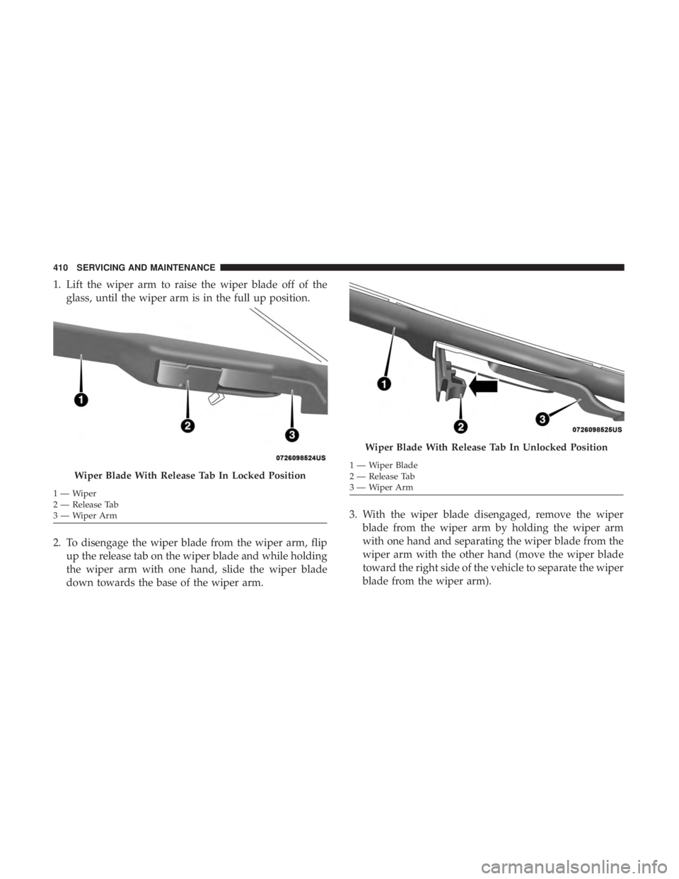
1. Lift the wiper arm to raise the wiper blade off of theglass, until the wiper arm is in the full up position.
2. To disengage the wiper blade from the wiper arm, flip up the release tab on the wiper blade and while holding
the wiper arm with one hand, slide the wiper blade
down towards the base of the wiper arm. 3. With the wiper blade disengaged, remove the wiper
blade from the wiper arm by holding the wiper arm
with one hand and separating the wiper blade from the
wiper arm with the other hand (move the wiper blade
toward the right side of the vehicle to separate the wiper
blade from the wiper arm).
Wiper Blade With Release Tab In Locked Position
1—Wiper
2 — Release Tab
3—WiperArm
Wiper Blade With Release Tab In Unlocked Position
1 — Wiper Blade
2 — Release Tab
3—WiperArm
410 SERVICING AND MAINTENANCE
Page 417 of 572
In unusual situations involving grossly malfunctioning
engine operation, a scorching odor may suggest severe and
abnormal catalyst overheating. If this occurs, stop the
vehicle, turn off the engine and allow it to cool. Service,
including a tune-up to manufacturer’s specifications,
should be obtained immediately.
To minimize the possibility of catalytic converter damage:
•Do not interrupt the ignition when the transmission is in
gear and the vehicle is in motion.
• Do not try to start the vehicle by pushing or towing the
vehicle.
• Do not idle the engine with any ignition components
disconnected or removed, such as when diagnostic
testing, or for prolonged periods during very rough idle
or malfunctioning operating conditions.
Cooling System
WARNING!
• You or others can be badly burned by hot engine
coolant (antifreeze) or steam from your radiator. If
you see or hear steam coming from under the hood,
(Continued)
WARNING! (Continued)
do not open the hood until the radiator has had time
to cool. Never open a cooling system pressure cap
when the radiator or coolant bottle is hot.
• Keep hands, tools, clothing, and jewelry away from
the radiator cooling fan when the hood is raised. The
fan starts automatically and may start at any time,
whether the engine is running or not.
• When working near the radiator cooling fan, discon-
nect the fan motor lead or turn the ignition to the
OFF mode. The fan is temperature controlled and can
start at any time the ignition is in the ON mode.
Engine Coolant Checks
Check the engine coolant (antifreeze) protection every 12
months (before the onset of freezing weather, where appli-
cable). If the engine coolant (antifreeze) is dirty, the system
should be drained, flushed, and refilled with fresh OAT
coolant (conforming to MS.90032) by an authorized dealer.
Check the front of the A/C condenser for any accumula-
tion of bugs, leaves, etc. If dirty, clean by gently spraying
water from a garden hose vertically down the face of the
condenser.
8
SERVICING AND MAINTENANCE 415
Page 432 of 572
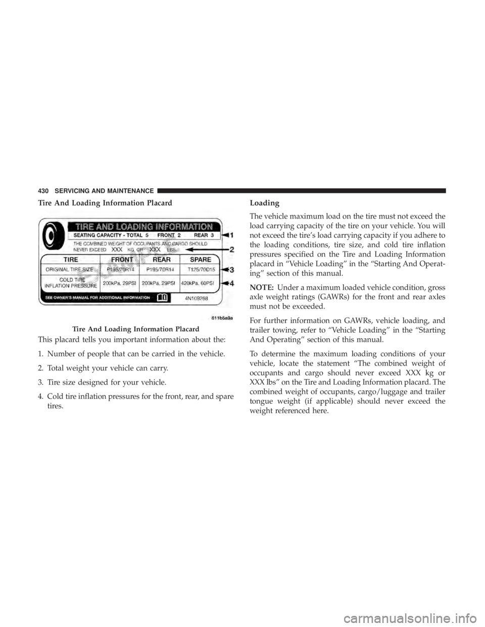
Tire And Loading Information Placard
This placard tells you important information about the:
1. Number of people that can be carried in the vehicle.
2. Total weight your vehicle can carry.
3. Tire size designed for your vehicle.
4. Cold tire inflation pressures for the front, rear, and sparetires.Loading
The vehicle maximum load on the tire must not exceed the
load carrying capacity of the tire on your vehicle. You will
not exceed the tire’s load carrying capacity if you adhere to
the loading conditions, tire size, and cold tire inflation
pressures specified on the Tire and Loading Information
placard in “Vehicle Loading” in the “Starting And Operat-
ing” section of this manual.
NOTE: Under a maximum loaded vehicle condition, gross
axle weight ratings (GAWRs) for the front and rear axles
must not be exceeded.
For further information on GAWRs, vehicle loading, and
trailer towing, refer to “Vehicle Loading” in the “Starting
And Operating” section of this manual.
To determine the maximum loading conditions of your
vehicle, locate the statement “The combined weight of
occupants and cargo should never exceed XXX kg or
XXX lbs” on the Tire and Loading Information placard. The
combined weight of occupants, cargo/luggage and trailer
tongue weight (if applicable) should never exceed the
weight referenced here.
Tire And Loading Information Placard
430 SERVICING AND MAINTENANCE