DODGE GRAND CARAVAN 2008 5.G Owners Manual
Manufacturer: DODGE, Model Year: 2008, Model line: GRAND CARAVAN, Model: DODGE GRAND CARAVAN 2008 5.GPages: 531, PDF Size: 7.72 MB
Page 221 of 531
UNDERSTANDING YOUR INSTRUMENT PANEL
CONTENTS
mInstrument Panels And Controls............223
mBase Instrument Cluster..................224
mPremium Instrument Cluster...............225
mInstrument Cluster Descriptions............226
mCompass Mini-Trip Computer (CMTC) Ð
If Equipped...........................238
NCompass Mini-Trip Computer (CMTC)
Odometer Displays....................238
NCompass Mini-Trip Computer (CMTC) Reset
Buttons............................238NCompass/Temperature Display...........240
mElectronic Vehicle Information Center (EVIC) Ð
If Equipped...........................241
NEVIC Displays.......................243
NTrip Functions.......................244
NCompass Display.....................246
NPersonal Settings
(Customer Programmable Features)........248
mRadio General Information................251
NRadio Broadcast Signals.................2514
Page 222 of 531
mSales Code REQ Ð AM/FM Stereo Radio And
6±Disc CD/DVD Changer
(MP3/WMA AUX Jack)..................252
NOperating Instructions - Radio Mode.......252
NOperation Instructions - (Disc Mode For CD
And MP3/WMA Audio Play, DVD-Video)....260
NNotes On Playing MP3/WMA Files........262
NList Button
(Disc Mode For MP3/WMA Play)..........265
NInfo Button
(Disc Mode For MP3/WMA Play)..........265
mSales Code RES Ð AM/FM Stereo Radio With
CD Player (MP3 AUX Jack)................268
NOperating Instructions - Radio Mode.......268NOperation Instructions - CD Mode For CD
And MP3 Audio Play..................274
NNotes On Playing MP3 Files.............276
NList Button (CD Mode For MP3 Play).......279
NInfo Button (CD Mode For MP3 Play).......279
mSales Code REN Ð Multimedia System Ð
If Equipped...........................280
NOperating Instructions Ð Satellite Radio
(If Equipped)........................281
NOperating Instructions Ð Voice Recognition
System (VR) (If Equipped)...............281
NOperating Instructions Ð Hands-Free
Communication (UConnectt) (If Equipped) . . . 281
NClock Setting Procedure.................281
220 UNDERSTANDING YOUR INSTRUMENT PANEL
Page 223 of 531
mSales Code RER Ð Multimedia System Ð
If Equipped...........................283
NOperating Instructions Ð Satellite Radio.....284
NOperating Instructions Ð Hands-Free
Communication (UConnectt) (If Equipped) . . . 284
NClock Setting Procedure.................285
mSatellite Radio Ð If Equipped
(REN/REQ/RER/RES/REU Radios Only).....287
NSystem Activation.....................287
NElectronic Serial Number/Sirius Identification
Number (ESN/SID)....................287
NSelecting Satellite Mode.................288
NSatellite Antenna......................288
NReception Quality.....................289NOperating Instructions - Satellite Mode......289
NOperating Instructions - Hands-Free Phone
(If Equipped)........................292
NOperating Instructions - Video Entertainment
System (VESt) (If Equipped).............292
mUniversal Consumer Interface (UCI) Ð
If Equipped...........................292
NConnecting The iPodtDevice............293
NControlling The iPodtUsing Radio Buttons . . . 293
NPlay Mode..........................293
NList Or Browse Mode..................295
mSirius Backseat TVŸ Ð If Equipped.........297
mVideo Entertainment System (VESt)Ð
If Equipped...........................297
UNDERSTANDING YOUR INSTRUMENT PANEL 221
4
Page 224 of 531
mRadio Operation And Cellular Phones........299
mRemote Sound System Controls Ð If Equipped . . 299
NRadio Operation......................299
NCD Player..........................300
mCD/DVD Maintenance...................300
mClimate Controls.......................301
NManual Heating, Ventilation And Air
Conditioning (HVAC) System.............301
NRear Manual Climate Control Zone Ð
If Equipped.........................307
NAutomatic Temperature Control (ATC) Ð
If Equipped.........................309NSummer Operation....................318
NWinter Operation.....................318
NVacation/Storage.....................318
NWindow Fogging.....................318
NOutside Air Intake....................319
NOperating Tips.......................319
NA/C Air Filter Ð If Equipped............320
mElectric Rear Window Defroster Ð
If Equipped...........................320
222 UNDERSTANDING YOUR INSTRUMENT PANEL
Page 225 of 531
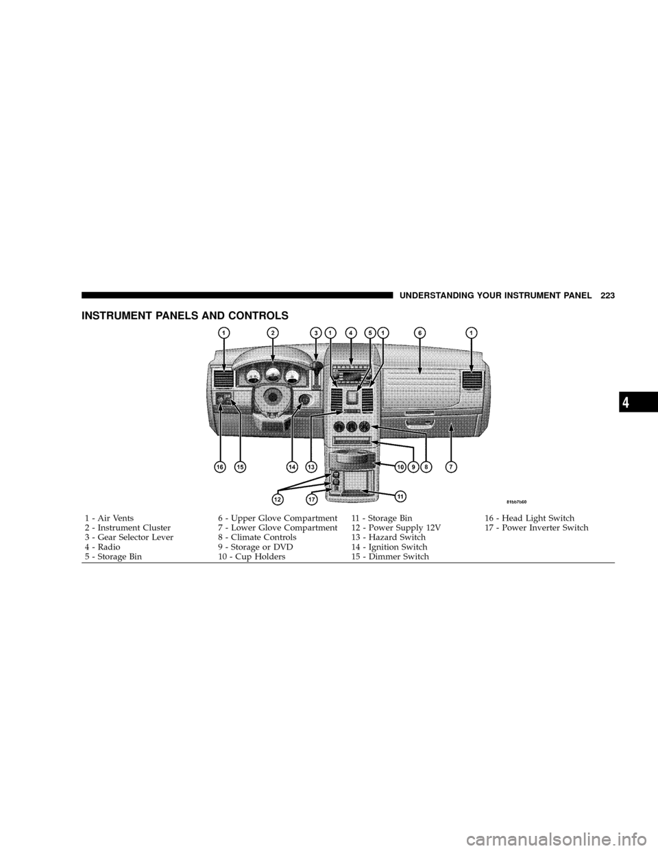
INSTRUMENT PANELS AND CONTROLS
1 - Air Vents 6 - Upper Glove Compartment 11 - Storage Bin 16 - Head Light Switch
2 - Instrument Cluster 7 - Lower Glove Compartment 12 - Power Supply 12V 17 - Power Inverter Switch
3 - Gear Selector Lever 8 - Climate Controls 13 - Hazard Switch
4 - Radio 9 - Storage or DVD 14 - Ignition Switch
5 - Storage Bin 10 - Cup Holders 15 - Dimmer SwitchUNDERSTANDING YOUR INSTRUMENT PANEL 223
4
Page 226 of 531
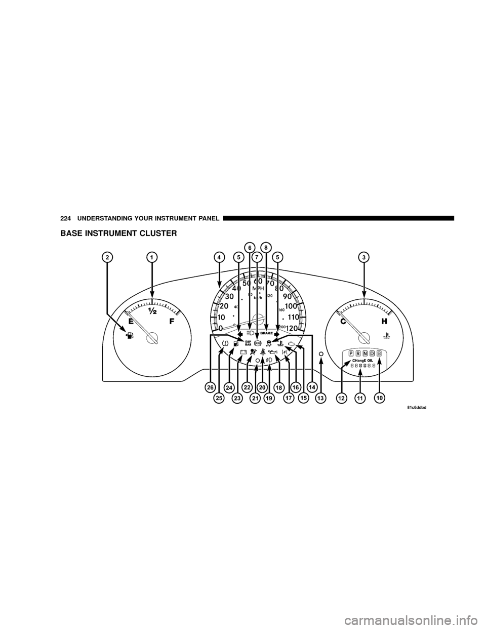
BASE INSTRUMENT CLUSTER
224 UNDERSTANDING YOUR INSTRUMENT PANEL
Page 227 of 531
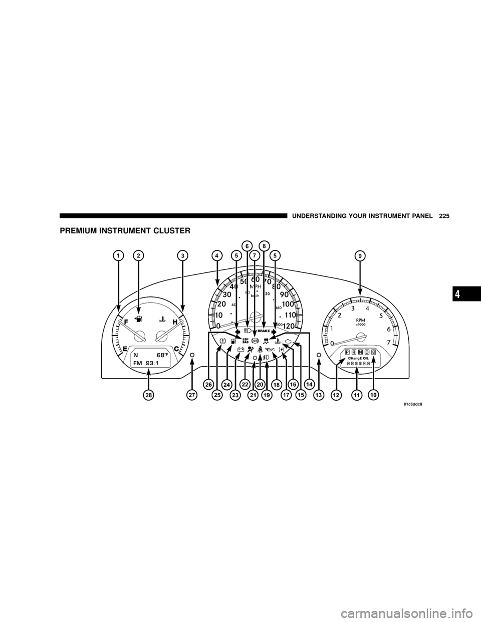
PREMIUM INSTRUMENT CLUSTER
UNDERSTANDING YOUR INSTRUMENT PANEL 225
4
Page 228 of 531
INSTRUMENT CLUSTER DESCRIPTIONS
1. Fuel Gauge
The pointer shows the level of fuel in the fuel tank when
the ignition switch is in the ON position.
2. Fuel Door Reminder
The arrow in this symbol is a reminder that the
Fuel Filler Door is located on the left side of the
vehicle.
3. Temperature Gauge
The temperature gauge shows engine coolant tempera-
ture. Any reading within the normal range indicates that
the engine cooling system is operating satisfactorily.The gauge pointer will likely indicate a higher tempera-
ture when driving in hot weather, up mountain grades,
or when towing a trailer. It should not be allowed to
exceed the upper limits of the normal operating range.
CAUTION!
Driving with a hot engine cooling system could
damage your vehicle. If temperature gauge reads
ªHª, pull over and stop the vehicle. Idle the vehicle
with the air conditioner turned off until the pointer
drops back into the normal range. If the pointer
remains on the ªHº, and you hear continuous chimes,
turn the engine off immediately, and call an autho-
rized dealer for service.
226 UNDERSTANDING YOUR INSTRUMENT PANEL
Page 229 of 531
WARNING!
A hot engine cooling system is dangerous. You or
others could be badly burned by steam or boiling
coolant. You may want to call an authorized dealer if
your vehicle overheats. If you decide to look under
the hood yourself, see Section 7 of this manual.
Follow the warnings under the Cooling System Pres-
sure Cap paragraph.
4. Speedometer
Indicates vehicle speed.
5. Turn Signal Indicators
The arrow will flash with the exterior turn signal
when the turn signal lever is operated.
If the vehicle electronics sense that the vehicle has
traveled about one mile with the turn signals on, acontinuous chime will sound to alert you to turn the
signals off. If either indicator flashes at a rapid rate, check
for a defective outside light bulb.
6. High Beam Light
This light shows that the headlights are on high
beam. Pull the turn signal lever towards the
steering wheel to switch the headlights from high or low
beam.
7. Anti-Lock Brake System Light
This light monitors the Anti-Lock Brake Sys-
tem. The light will turn on when the ignition
switch is turned to the ON position and may
stay on for as long as four seconds.
If the ABS light remains on or turns on while driving, it
indicates that the Anti-Lock portion of the brake system
is not functioning and that service is required. However,
the conventional brake system will continue to operate
normally if the BRAKE warning light is not on.
UNDERSTANDING YOUR INSTRUMENT PANEL 227
4
Page 230 of 531
If the ABS light is on, the brake system should be serviced
as soon as possible to restore the benefits of Anti-Lock
brakes. If the ABS light does not turn on when the
Ignition switch is turned to the ON position, have the
light inspected by an authorized dealer.
8. Brake System Warning Light
This light monitors various brake functions,
including brake fluid level and parking brake
application. If the brake light turns on, it may
indicate that the parking brake is applied, that
the brake fluid level is low, or that there is a problem with
the anti-lock brake system (if equipped).
The dual brake system provides a reserve braking capac-
ity in the event of a failure to a portion of the hydraulic
system. Failure of either half of the dual brake system is
indicated by the Brake Warning Light which will turn on
when the brake fluid level in the master cylinder has
dropped below a specified level.The light will remain on until the cause is corrected.
NOTE:The light may flash momentarily during sharp
cornering maneuvers which change fluid level condi-
tions. The vehicle should have service performed, and
the brake fluid level checked.
If brake failure is indicated, immediate repair is neces-
sary.
WARNING!
Driving a vehicle with the brake light on is danger-
ous. Part of the brake system may have failed. It will
take longer to stop the vehicle. You could have an
accident. Have the vehicle checked immediately.
Vehicles equipped with the Anti-Lock Brake System
(ABS), are also equipped with Electronic Brake Force
Distribution (EBD). In the event of an EBD failure, the
228 UNDERSTANDING YOUR INSTRUMENT PANEL