wiring DODGE GRAND CARAVAN 2009 5.G Owners Manual
[x] Cancel search | Manufacturer: DODGE, Model Year: 2009, Model line: GRAND CARAVAN, Model: DODGE GRAND CARAVAN 2009 5.GPages: 535, PDF Size: 18.61 MB
Page 74 of 535
WARNING!Deployed airbags and seat belt pretensioners cannot
protect you in another collision. Have the airbags,
seat belt pretensioners, and the front passenger seat
belt retractor assembly replaced by an authorized
dealer as soon as possible. Also, have the Occupant
Restraint Controller (ORC) system serviced as well.
Maintaining Your Airbag System
WARNING!
Modifications to any part of the airbag system
could cause it to fail when you need it. You could
be injured if the airbag system is not there to
protect you. Do not modify the components or
wiring, including adding any kind of badges or
stickers to the steering wheel hub trim cover or the
upper right side of the instrument panel. Do not
modify the front bumper, vehicle body structure,
or add aftermarket side steps or running boards.
It is dangerous to try to repair any part of the
airbag system yourself. Be sure to tell anyone who
works on your vehicle that it has an airbag system. (Continued)
72 THINGS TO KNOW BEFORE STARTING YOUR VEHICLE
Page 407 of 535
Towing Requirements — Trailer Lights and WiringWhenever you pull a trailer, regardless of the trailer size,
stop lights and turn signals on the trailer are required for
motoring safety.
The Trailer Tow Package may include a four-pin or a
seven-pin wiring harness. Use a factory approved trailer
harness and connector.
NOTE:
Do not cut or splice wiring into the vehicles
wiring harness.
The electrical connections are all complete to the vehicle
but you must mate the harness to a trailer connector.
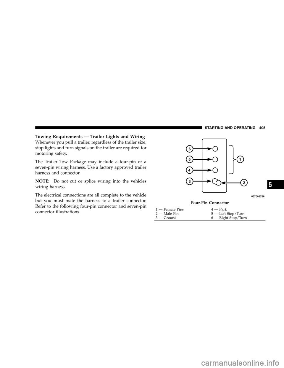
Refer to the following four-pin connector and seven-pin
connector illustrations. Four-Pin Connector
1 — Female Pins
4 — Park
2 —
Male Pin 5 — Left Stop/Turn
3 — Ground 6 — Right Stop/Turn
STARTING AND OPERATING 405 5
Page 479 of 535
5. Connect the wiring connector to bulb and slide red
lock tab forward.
Front Park/Turn Signal Lamps
1. Raise the hood to access the rear of the headlamp
housing.
2. Twist the turn signal socket and remove from the
headlamp housing, then pull the bulb out.
3. Push the new bulb into the socket and reinstall the
socket by twisting until locked into the headlamp
housing.
Fog Lamps
NOTE:Access to the fog lamp bulb is from the rear of
the fascia. On the left rear side of the fascia, remove the
push pin and lower the hinged access door on the air
dam. 1. From behind the bumper fascia, or the access panel on
the air dam, twist the bulb counterclockwise, and remove
bulb. CAUTION!
Do not touch the new bulb with your fingers. Oil
contamination will severely shorten bulb life. If the
bulb comes in contact with an oily surface, clean the
bulb with rubbing alcohol.
2. Disconnect the wire harness from the bulb.
3. Reconnect the wiring harness to the new bulb and
reinstall the bulb by twisting clockwise.
MAINTAINING YOUR VEHICLE 477 7
Page 530 of 535
Changing . . . . . . . . . . . . . . . . . . . . . . . . . . . . 411
Compact Spare . . . . . . . . . . . . . . . . . . . . . . . . 363
Flat Changing . . . . . . . . . . . . . . . . . . . . . . . . 421
General Information . . . . . . . . . . . . . . . . . . . . 360
High Speed . . . . . . . . . . . . . . . . . . . . . . . . . . 362
Inflation Pressures . . . . . . . . . . . . . . . . . . . . . 361
Jacking . . . . . . . . . . . . . . . . . . . . . . . . . . . 411,415
Life of Tires . . . . . . . . . . . . . . . . . . . . . . . . . . 366
Load Capacity . . . . . . . . . . . . . . . . . . . . . 356,357
Pressure Monitor System (TPMS) . . . . . . . . . . . 370
Pressure Warning Light . . . . . . . . . . . . . . . . . . 249
Quality Grading . . . . . . . . . . . . . . . . . . . . . . . 509
Radial . . . . . . . . . . . . . . . . . . . . . . . . . . . . . . 363
Replacement . . . . . . . . . . . . . . . . . . . . . . . . . 366
Rotation . . . . . . . . . . . . . . . . . . . . . . . . . . . . 369
Safety . . . . . . . . . . . . . . . . . . . . . . . . . . . 352,360
Sizes . . . . . . . . . . . . . . . . . . . . . . . . . . . . . . . 353
Snow Tires . . . . . . . . . . . . . . . . . . . . . . . . . . . 369
Spare Tire . . . . . . . . . . . . . . . . . . . . . . . . . . . 413Spinning . . . . . . . . . . . . . . . . . . . . . . . . . . . . 364
Tread Wear Indicators . . . . . . . . . . . . . . . . . . . 365
Tongue Weight/Trailer Weight . . . . . . . . . . . . . . 400
Towing . . . . . . . . . . . . . . . . . . . . . . . . . . . . . . . 393
24-Hour Towing Assistance . . . . . . . . . . . . . . . 127
Disabled Vehicle . . . . . . . . . . . . . . . . . . . . . . . 427
Guide . . . . . . . . . . . . . . . . . . . . . . . . . . . . . . 398
Recreational . . . . . . . . . . . . . . . . . . . . . . . 408,429
Weight . . . . . . . . . . . . . . . . . . . . . . . . . . . . . . 398
Towing Assistance . . . . . . . . . . . . . . . . . . . . . . . 127
Traction Control . . . . . . . . . . . . . . . . . . . . . . . . . 347
Traction Control Switch . . . . . . . . . . . . . . . . . . . 347
Trailer Towing . . . . . . . . . . . . . . . . . . . . . . . . . . 393 Cooling System Tips . . . . . . . . . . . . . . . . . . . . 408
Hitches . . . . . . . . . . . . . . . . . . . . . . . . . . . . . 397
Minimum Requirements . . . . . . . . . . . . . . . . . 401
Trailer and Tongue Weight . . . . . . . . . . . . . . . 400
Wiring . . . . . . . . . . . . . . . . . . . . . . . . . . . . . . 405
Trailer Towing Guide . . . . . . . . . . . . . . . . . . . . . 398
528 INDEX
Page 534 of 535
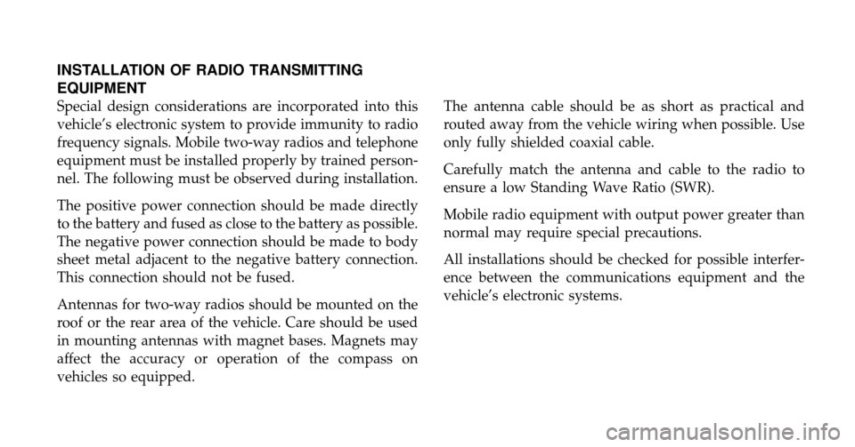
INSTALLATION OF RADIO TRANSMITTING
EQUIPMENT
Special design considerations are incorporated into this
vehicle’s electronic system to provide immunity to radio
frequency signals. Mobile two-way radios and telephone
equipment must be installed properly by trained person-
nel. The following must be observed during installation.
The positive power connection should be made directly
to the battery and fused as close to the battery as possible.
The negative power connection should be made to body
sheet metal adjacent to the negative battery connection.
This connection should not be fused.
Antennas for two-way radios should be mounted on the
roof or the rear area of the vehicle. Care should be used
in mounting antennas with magnet bases. Magnets may
affect the accuracy or operation of the compass on
vehicles so equipped.The antenna cable should be as short as practical and
routed away from the vehicle wiring when possible. Use
only fully shielded coaxial cable.
Carefully match the antenna and cable to the radio to
ensure a low Standing Wave Ratio (SWR).
Mobile radio equipment with output power greater than
normal may require special precautions.
All installations should be checked for possible interfer-
ence between the communications equipment and the
vehicle’s electronic systems.