Door DODGE GRAND CARAVAN 2010 5.G Owner's Manual
[x] Cancel search | Manufacturer: DODGE, Model Year: 2010, Model line: GRAND CARAVAN, Model: DODGE GRAND CARAVAN 2010 5.GPages: 88, PDF Size: 13.56 MB
Page 44 of 88
Auxiliary Audio/Video Input Jacks
• The AUX jacks are located on the drivers side rear trim panel behind the sliding door.
• Connect the video game or other external media devises to the AUX jacks following thecolor coding for the VES™ jacks.
• Using either the touch-screen radio or remote control, select AUX from the REAR VES™ CONTROL or the MODE SELECTION screen.
• Refer to the Uconnect™ Multimedia – Video Entertainment System (VES)™ section in the Uconnect™ User's Manual on the DVD for further details.
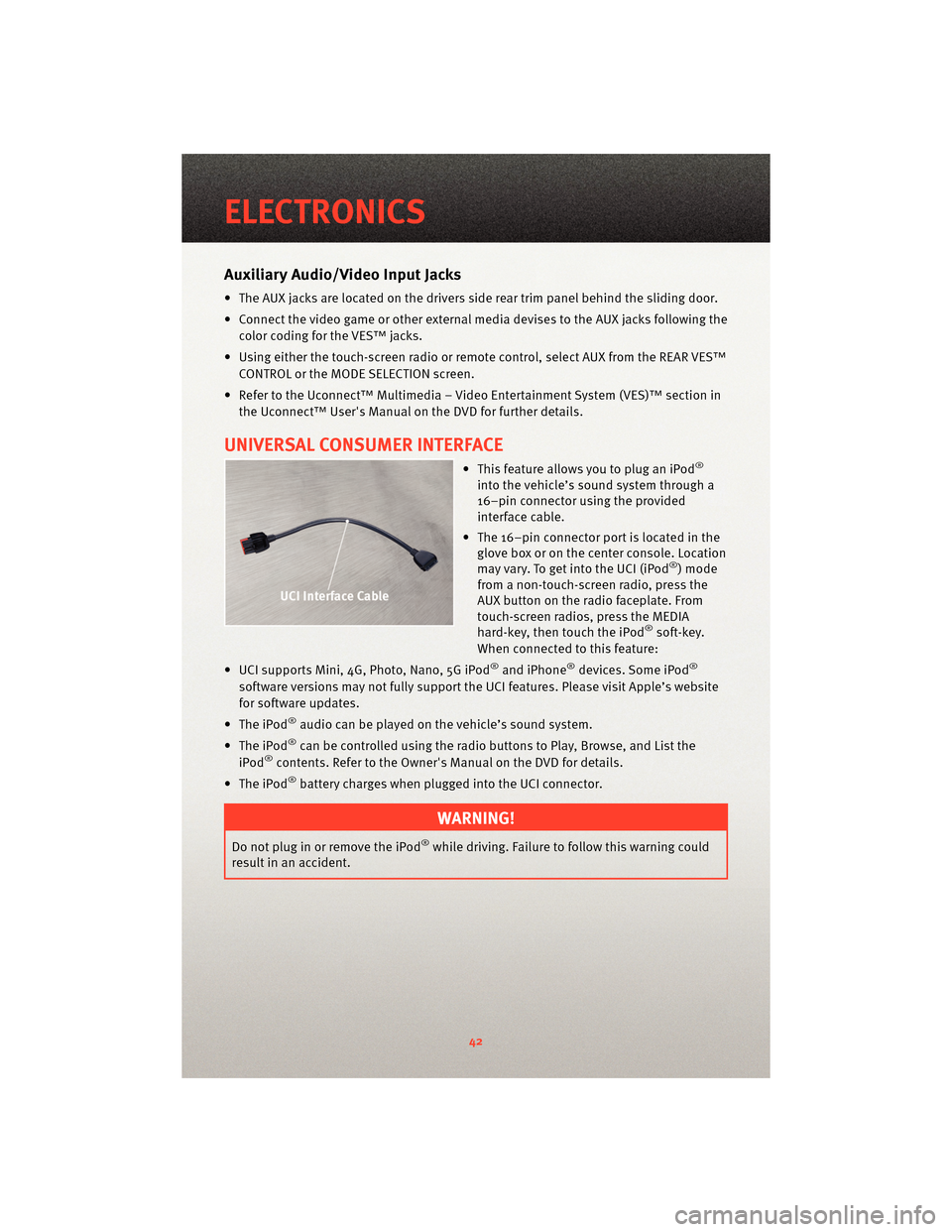
UNIVERSAL CONSUMER INTERFACE
• This feature allows you to plug an iPod®
into the vehicle’s sound system through a
16–pin connector using the provided
interface cable.
• The 16–pin connector port is located in the glove box or on the center console. Location
may vary. To get into the UCI (iPod
®) mode
from a non-touch-screen radio, press the
AUX button on the radio faceplate. From
touch-screen radios, press the MEDIA
hard-key, then touch the iPod
®soft-key.
When connected to this feature:
• UCI supports Mini, 4G, Photo, Nano, 5G iPod
®and iPhone®devices. Some iPod®
software versions may not fully support the UCI features. Please visit Apple’s website
for software updates.
• The iPod
®audio can be played on the vehicle’s sound system.
• The iPod
®can be controlled using the radio buttons to Play, Browse, and List the
iPod®contents. Refer to the Owner's Manual on the DVD for details.
• The iPod
®battery charges when plug ged into the UCI connector.
WARNING!
Do not plug in or remove the iPod®while driving. Failure to follow this warning could
result in an accident.
ELECTRONICS
42
Page 45 of 88
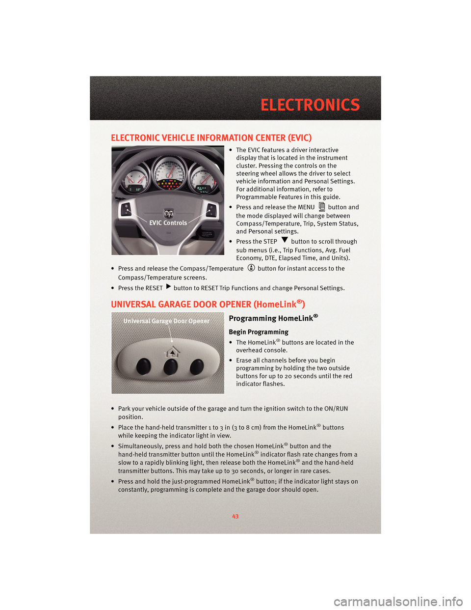
ELECTRONIC VEHICLE INFORMATION CENTER (EVIC)
• The EVIC features a driver interactivedisplay that is located in the instrument
cluster. Pressing the controls on the
steering wheel allows the driver to select
vehicle information and Personal Settings.
For additional information, refer to
Programmable Features in this guide.
• Press and release the MENU
button and
the mode displayed will change between
Compass/Temperature, Trip, System Status,
and Personal settings.
• Press the STEP
button to scroll through
sub menus (i.e., Trip Functions, Avg. Fuel
Economy, DTE, Elapsed Time, and Units).
• Press and release the Compass/Temperature
button for instant access to the
Compass/Temperature screens.
• Press the RESET
button to RESET Trip Functions and change Personal Settings.
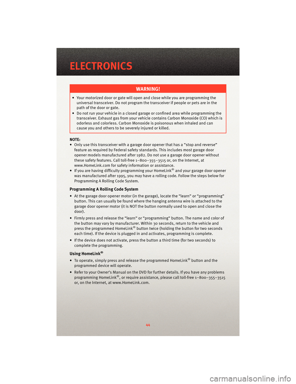
UNIVERSAL GARAGE DOOR OPENER (HomeLink®)
Programming HomeLink®
Begin Programming
• The HomeLink®buttons are located in the
overhead console.
• Erase all channels before you begin programming by holding the two outside
buttons for up to 20 seconds until the red
indicator flashes.
• Park your vehicle outside of the garage and turn the ignition switch to the ON/RUN position.
• Place the hand-held transmitter 1 to 3 in (3 to 8 cm) from the HomeLink
®buttons
while keeping the indicator light in view.
• Simultaneously, press and hold both the chosen HomeLink
®button and the
hand-held transmitter button until the HomeLink®indicator flash rate changes from a
slow to a rapidly blinking light, then release both the HomeLink®and the hand-held
transmitter buttons. This may take up to 30 seconds, or longer in rare cases.
• Press and hold the just-programmed HomeLink
®button; if the indicator light stays on
constantly, programming is complete and the garage door should open.
43
ELECTRONICS
Page 46 of 88
WARNING!
• Your motorized door or gate will open and close while you are programming theuniversal transceiver. Do not program the transceiver if people or pets are in the
path of the door or gate.
• Do not run your vehicle in a closed garage or confined area while programming the transceiver. Exhaust gas from your vehicle contains Carbon Monoxide (CO) which is
odorless and colorless. Carbon Monoxide is poisonous when inhaled and can
cause you and others to be severely injured or killed.
NOTE:
• Only use this transceiver with a garage door opener that has a “stop and reverse” feature as required by Federal safety standards. This includes most garage door
opener models manufactured after 1982. Do not use a garage door opener without
these safety features. Call toll-free 1–800–355–3515 or, on the Internet, at
www.HomeLink.com for safety inf ormation orassistance.
• If you are having difficulty programming your HomeLink
®and your garage door opener
was manufactured after 1995, you may have a rolling code. Follow the steps below for
Programming A Rolling Code System.
Programming A Rolling Code System
• At the garage door opener motor (in the gara ge), locate the “learn” or “programming”
button. This can usually be found where the hanging antenna wire is attached to the
garage door opener motor (it is NOT the button normally used to open and close the
door).
• Firmly press and release the “learn” or “programming” button. The name and color of
the button may vary by manufacturer. Within 30 seconds, return to the vehicle and
press the programmed HomeLink
®button twice (holding the button for two seconds
each time). If the device is plugged in and activates, programming is complete.
• If the device does not activate, press the button a third time (for two seconds) to
complete the programming.
Using HomeLink®
• To operate, simply press and release the programmed HomeLink®button and the
programmed device will operate.
• Refer to your Owner’s Manual on the DVD for further details. If you have any problems programming HomeLink
®, or require assistance, please call toll-free 1–800–355–3515
or, on the Internet, at www.HomeLink.com.
ELECTRONICS
44
Page 61 of 88
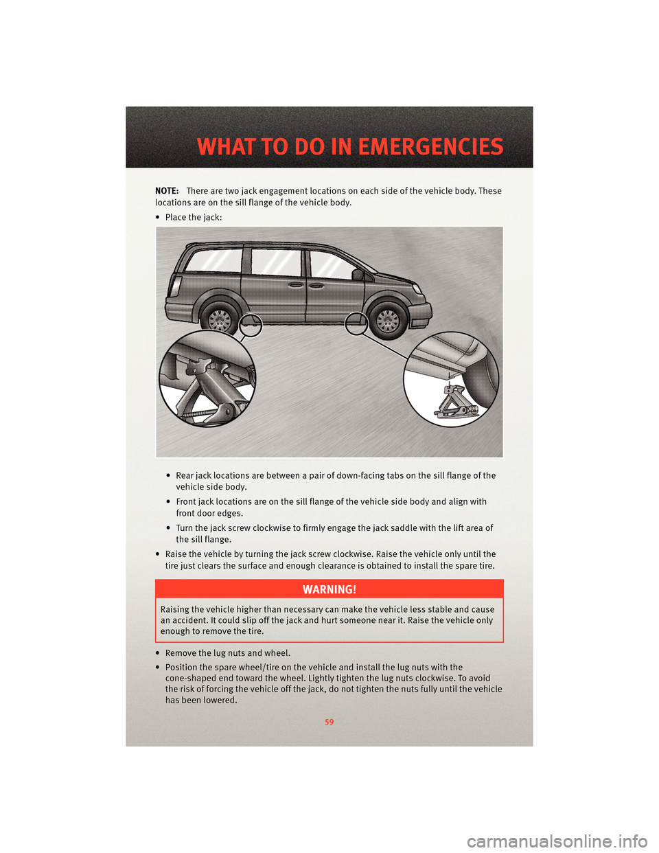
NOTE:There are two jack engagement locations on each side of the vehicle body. These
locations are on the sill flange of the vehicle body.
• Place the jack:
• Rear jack locations are between a pair of down-facing tabs on the sill flange of thevehicle side body.
• Front jack locations are on the sill flange of the vehicle side body and align with front door edges.
• Turn the jack screw clockwise to firmly engage the jack saddle with the lift area of the sill flange.
• Raise the vehicle by turning the jack screw clockwise. Raise the vehicle only until the tire just clears the surface and enough clearance is obtained to install the spare tire.
WARNING!
Raising the vehicle higher than necessary can make the vehicle less stable and cause
an accident. It could slip off the jack and hurt someone near it. Raise the vehicle only
enough to remove the tire.
• Remove the lug nuts and wheel.
• Position the spare wheel/tire on the vehicle and install the lug nuts with the cone-shaped end toward the wheel. Lightly tight en the lug nuts clockwise. To avoid
the risk of forcing the vehicle off the jack, do not tighten the nuts fully until the vehicle
has been lowered.
59
WHAT TO DO IN EMERGENCIES
Page 69 of 88
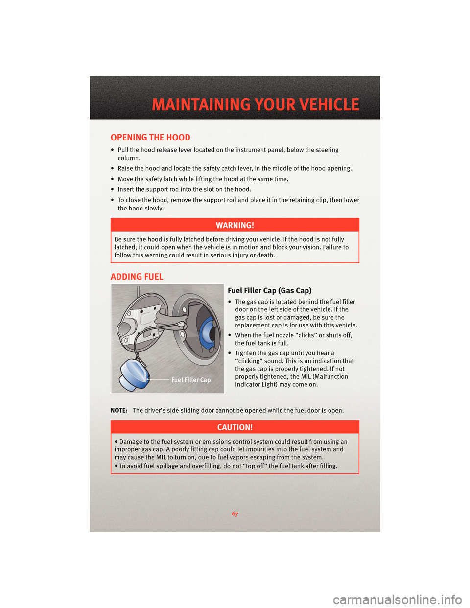
OPENING THE HOOD
• Pull the hood release lever locatedon the instrument panel, below the steering
column.
• Raise the hood and locate the safety catc h lever, in the middle of the hood opening.
• Move the safety latch while lifting the hood at the same time.
• Insert the support rod into the slot on the hood.
• To close the hood, remove the support rod and place it in the retaining clip, then lower the hood slowly.
WARNING!
Be sure the hood is fully latched before driving your vehicle. If the hood is not fully
latched, it could open when the vehicle is in motion and block your vision. Failure to
follow this warning could result in serious injury or death.
ADDING FUEL
Fuel Filler Cap (Gas Cap)
• The gas cap is located behind the fuel filler door on the left side of the vehicle. If the
gas cap is lost or damaged, be sure the
replacement cap is for use with this vehicle.
• When the fuel nozzle “clicks” or shuts off, the fuel tank is full.
• Tighten the gas cap until you hear a “clicking” sound. This is an indication that
the gas cap is properly tightened. If not
properly tightened, the MIL (Malfunction
Indicator Light) may come on.
NOTE: The driver’s side sliding door cannot be opened while the fuel door is open.
CAUTION!
• Damage to the fuel system or emissions control sy stem could result from using an
improper gas cap. A poorly fitting cap could le t impurities into the fuel system and
may cause the MIL to turn on, due to fuel vapors escaping from the system.
• To avoid fuel spillage and overfilling, do not “top off” the fuel tank after filling.
67
MAINTAINING YOUR VEHICLE
Page 77 of 88
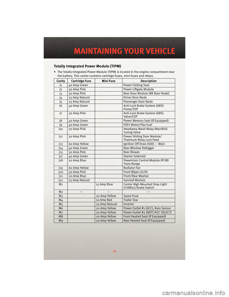
TotallyIntegrated Power Module (TIPM)
• The Totally Integrated Power Module (TIPM) is located in the engine compartment near
the battery. This center contains cartridge fuses, mini-fuses and relays.
Cavity Cartridge Fuse Mini-Fuse Description
J1 40 Amp Green Power Folding Seat
J2 30 Amp Pink Power Liftgate Module
J3 30 Amp Pink Rear Door Module (RR Door Node)
J4 25 Amp Natural Driver Door Node
J5 25 Amp Natural Passenger Door Node
J6 40 Amp Green Anti-Lock Brake System (ABS)
Pump/ESP
J7 30 Amp Pink Anti-Lock Brake System (ABS)
Valve/ESP
J8 40 Amp Green Power Memory Seat (If Equipped)
J9 40 Amp Green PZEV Motor/Flex Fuel
J10 30 Amp Pink Headlamp Wash Relay/Manifold
Tuning Valve
J11 30 Amp Pink Power Sliding Door Module/
Thatchum Relay Lock Feed
J13 60 Amp Yellow Ignition Off Draw (IOD) — Main
J14 40 Amp Green Rear Window Defogger
J15 30 Amp Pink Rear Blower
J17 40 Amp Green Starter Solenoid
J18 20 Amp Blue Powertrain Control Module (PCM)
Trans Range
J19 60 Amp Yellow Radiator Fan
J20 30 Amp Pink Front Wiper LO/HI
J21 20 Amp Blue Front/Rear Washer
J22 25 Amp Natural Sunroof Module
M1 15 Amp Blue Center High Mounted Stop Light
(CHMSL)/Brake Switch
M2 — — —
M3 20 Amp Yellow Spare Fuse
M4 10 Amp Red Trailer Tow
M5 25 Amp Natural Inverter
M6 20 Amp Yellow Power Outlet #1 (ACC), Rain Sensor
M7 20 Amp Yellow Power Outlet #2 (BATT/ACC SELECT)
M8 20 Amp Yellow Front Heated Seat (If Equipped)
M9 20 Amp Yellow Rear Heated Seat (If Equipped)
75
MAINTAINING YOUR VEHICLE
Page 78 of 88
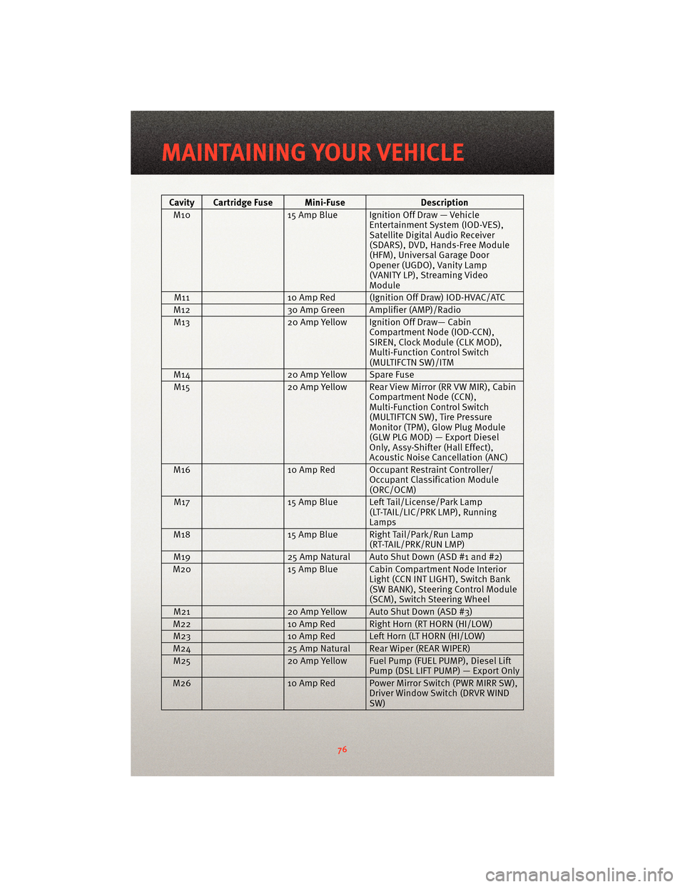
Cavity Cartridge Fuse Mini-FuseDescription
M10 15 Amp Blue Ignition Off Draw — Vehicle
Entertainment System (IOD-VES),
Satellite Digital Audio Receiver
(SDARS), DVD, Hands-Free Module
(HFM), Universal Garage Door
Opener (UGDO), Vanity Lamp
(VANITY LP), Streaming Video
Module
M11 10 Amp Red (Ignition Off Draw) IOD-HVAC/ATC
M12 30 Amp Green Amplifier (AMP)/Radio
M13 20 Amp Yellow Ignition Off Draw— Cabin
Compartment Node (IOD-CCN),
SIREN, Clock Module (CLK MOD),
Multi-Function Control Switch
(MULTIFCTN SW)/ITM
M14 20 Amp Yellow Spare Fuse
M15 20 Amp Yellow Rear View Mirror (RR VW MIR), Cabin
Compartment Node (CCN),
Multi-Function Control Switch
(MULTIFTCN SW), Tire Pressure
Monitor (TPM), Glow Plug Module
(GLW PLG MOD) — Export Diesel
Only, Assy-Shifter (Hall Effect),
Acoustic Noise Cancellation (ANC)
M16 10 Amp Red Occupant Restraint Controller/
Occupant Classification Module
(ORC/OCM)
M17 15 Amp Blue Left Tail/License/Park Lamp
(LT-TAIL/LIC/PRK LMP), Running
Lamps
M18 15 Amp Blue Right Tail/Park/Run Lamp
(RT-TAIL/PRK/RUN LMP)
M19 25 Amp Natural Auto Shut Down (ASD #1 and #2)
M20 15 Amp Blue Cabin Compartment Node Interior
Light (CCN INT LIGHT), Switch Bank
(SW BANK), Steering Control Module
(SCM), Switch Steering Wheel
M21 20 Amp Yellow Auto Shut Down (ASD #3)
M22 10 Amp Red Right Horn (RT HORN (HI/LOW)
M23 10 Amp Red Left Horn (LT HORN (HI/LOW)
M24 25 Amp Natural Rear Wiper (REAR WIPER)
M25 20 Amp Yellow Fuel Pump (FUEL PUMP), Diesel Lift
Pump (DSL LIFT PUMP) — Export Only
M26 10 Amp Red Power Mirror Switch (PWR MIRR SW),
Driver Window Switch (DRVR WIND
SW)
MAINTAINING YOUR VEHICLE
76
Page 79 of 88
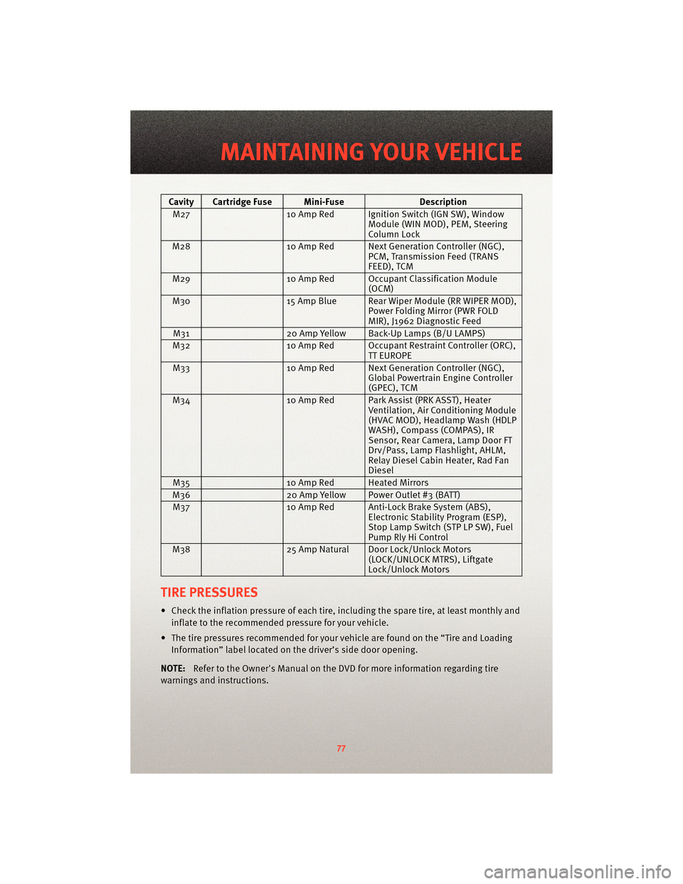
Cavity Cartridge Fuse Mini-FuseDescription
M27 10 Amp Red Ignition Switch (IGN SW), Window
Module (WIN MOD), PEM, Steering
Column Lock
M28 10 Amp Red Next Generation Controller (NGC),
PCM, Transmission Feed (TRANS
FEED), TCM
M29 10 Amp Red Occupant Classification Module
(OCM)
M30 15 Amp Blue Rear Wiper Module (RR WIPER MOD),
Power Folding Mirror (PWR FOLD
MIR), J1962 Diagnostic Feed
M31 20 Amp Yellow Back-Up Lamps (B/U LAMPS)
M32 10 Amp Red Occupant Restraint Controller (ORC),
TT EUROPE
M33 10 Amp Red Next Generation Controller (NGC),
Global Powertrain Engine Controller
(GPEC), TCM
M34 10 Amp Red ParkAssist(PRK ASST), Heater
Ventilation, Air Conditioning Module
(HVAC MOD), Headlamp Wash (HDLP
WASH), Compass (COMPAS), IR
Sensor, Rear Camera, Lamp Door FT
Drv/Pass , Lamp Flas hlight, AHLM,
Relay Diesel Cabin Heater, Rad Fan
Diesel
M35 10 Amp Red Heated Mirrors
M36 20 Amp Yellow Power Outlet #3 (BATT)
M37 10 Amp Red Anti-Lock Brake System (ABS),
Electronic Stability Program (ESP),
Stop Lamp Switch (STP LP SW), Fuel
Pump Rly Hi Control
M38 25 Amp Natural Door Lock/Unlock Motors
(LOCK/UNLOCK MTRS), Liftgate
Lock/Unlock Motors
TIRE PRESSURES
• Check the inflation pressure of each tire, including the spare tire, at least monthly and
inflate to the recommended pressure for your vehicle.
• The tire pressures recommended for your vehicle are found on the “Tire and Loading Information” label located on the driver’s side door opening.
NOTE: Refer to the Owner's Manual on the DVD f or more information regarding tire
warnings and instructions.
77
MAINTAINING YOUR VEHICLE
Page 85 of 88
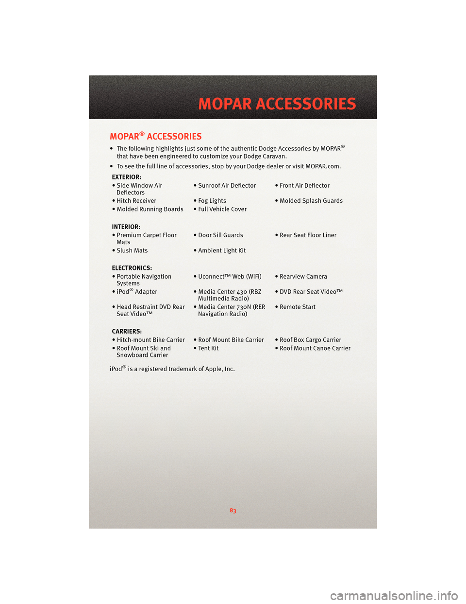
MOPAR®ACCESSORIES
• The following highlights just some of the authentic Dodge Accessories by MOPAR®
that have been engineered to customize your Dodge Caravan.
• To see the full line of accessories, sto p by your Dodge dealer or visitMOPAR.com.
EXTERIOR:
• Side Window Air Deflectors • Sunroof Air Deflector • Front Air Deflector
• Hitch Receiver • Fog Lights• Molded Splash Guards
• Molded Running Boards • Full Vehicle Cover
INTERIOR:
• Premium Carpet Floor Mats • Door Sill Guards • Rear Seat Floor Liner
• Slush Mats • Ambient Light Kit
ELECTRONICS:
• Portable Navigation Systems • Uconnect™ Web (WiFi) • Rearview Camera
•iPod
®Adapter • Media Center 430 (RBZ
Multimedia Radio) • DVD Rear Seat Video™
• Head Restraint DVD Rear Seat Video™ • Media Center 730N (RER
Navigation Radio) • Remote Start
CARRIERS:
• Hitch-mount Bike Carrier • Roof Mount Bike Carrier • Roof Box Cargo Carrier
• Roof Mount Ski and Snowboard Carrier • Tent Kit
• Roof Mount Canoe Carrier
iPod
®is a registered trademark of Apple, Inc.
83
MOPAR ACCESSORIES