tow DODGE GRAND CARAVAN 2010 5.G Owner's Manual
[x] Cancel search | Manufacturer: DODGE, Model Year: 2010, Model line: GRAND CARAVAN, Model: DODGE GRAND CARAVAN 2010 5.GPages: 88, PDF Size: 13.56 MB
Page 56 of 88
- Malfunction Indicator Light (MIL)
• Certain conditions, such as a loose or missing gas cap,poor fuel quality, etc., may
illuminate the MIL after engine start. The vehicle should be serviced if the light stays
on through several typical driving cycles. In most situations, the vehicle will drive
normally and not require towing.
• If the MIL flashes when the engine is running, serious conditions may exist that could lead to immediate loss of power or severe catalytic converter damage. We recommend
you do not operate the vehicle. Hav e the vehicle serviced immediately.
- Electronic StabilityProgram (ESP) Indicator Light/Brake Assist
System (BAS) Warning Light
• If the ESP/BAS warning light comes on continuously with the engine running, a
malfunction has been detected.
• If this light remains on after several ignition cycles, and the vehicle has been driven several miles (kilometers) at speeds g reater than 30 mph (48 km/h), we recommend
you drive to the nearest service center and have the vehicle serviced immediately.
- Charging System Light
• This light shows the status of the electrical ch arging system. If the charging system
light remains on, it means that the vehicle is experiencing a problem with the charging
system.
• We recommend you do not continue driving if the charging system light is on. Have the vehicle serviced immediately.
- Oil Pressure Warning Light
• This light indicates low engine oil pressure. If the light turns on while driving, stop thevehicle and shut off the engine as soon as possible. A chime will sound for four
minutes when this light turns on.
• We recommend you do not operate the vehicle or engine damage will occur. Have the vehicle serviced immediately.
- Anti-Lock Brake (ABS) Light
• This light monitors the Anti-Lock Brake System (ABS).
• If the light is not on during starting, stays on, or turns on while driving, we recommendyou drive to the nearest service center and have the vehicle serviced immediately.
- Electronic Throttle Control (ETC) Light
• This light informs you of a problem with the Electronic Throttle Control (ETC) system.
• If a problem is detected, the light will come on while the engine is running. Cycle theignition when the vehicle has completely stopped and the shift lever is placed in the
PARK position; the light should turn off.
WHAT TO DO IN EMERGENCIES
54
Page 57 of 88
• If the light remains lit with the engine running, your vehicle will usually be drivable;however, see an authorized service center immediately. If the light is flashing when
the engine is running, immediate service is required and you may experience reduced
performance, an elevated/rough idle or en gine stall and your vehicle may require
towing.
- Airbag Warning Light
• If the light is not on during starting, stays on, or turns on while driving, have the vehicle serviced by an authorized service center immediately.
Fuel Cap/Loose Gas Cap Message
• If a “gas cap” message (shown as gASCAP) appears, tighten the gas cap until a“clicking” sound is heard.
• Press the odometer reset button to turn the message off.
• If the message continues to appear for mor e than three days after tightening the gas
cap, see your authorized service center.
Oil Change Indicator
Message
• If an “oil change” message (shown as CHAngE OIL) appears and a single chime
sounds, it is time for your next required oil change.
Resetting The Light After Servicing
• Turn the ignition switch to the ON/RUN position (do not start engine).
• Fully depress the accelerator pedal three times within 10 seconds.
• Turn the ignition switch to the OFF/LOCK position.
IF YOUR ENGINE OVERHEATS
• In any of the following situations, you c an reduce the potential for overheating by
taking the appropriate action.
• On the highways — slow down.
• In city traffic — while stopped, shift tran smission intoNEUTRAL, but do not increase
engine idle speed.
NOTE: There are steps that you can take to slow down an impending overheat
condition:
• If your air conditioner (A/C) is on, turn it off. The A/C system adds heat to the engine cooling system and turning the A/C off can help remove this heat.
• You can also turn the Temperature Control to maximum heat, the Mode Control to floor and the Fan Control to high. This allows the heater core to act as a supplement to the
radiator and aids in removing heat from the engine cooling system.
• If the temperature reading does not re turn to normal, turn the engine off immediately.
• We recommend that you do not operate the vehicle or engine damage will occur. Have the vehicle serviced immediately.
55
WHAT TO DO IN EMERGENCIES
Page 59 of 88
Jack Location
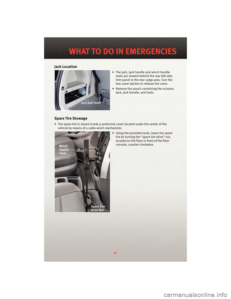
• The jack, jack handle and winch handletools are stowed behind the rear left side
trim panel in the rear cargo area. Turn the
two cover latches to release the cover.
• Remove the pouch cont aining the scissors
jack, jack handle, and tools.
Spare Tire Stowage
• The spare tire is stored inside a protective cover located under the center of the
vehicle by means of a cable winch mechanism.
• Using the provided tools, lower the sparetire by turning the “spare tire drive” nut,
located on the floor in front of the floor
console, counter-clockwise.
57
WHAT TO DO IN EMERGENCIES
Page 61 of 88
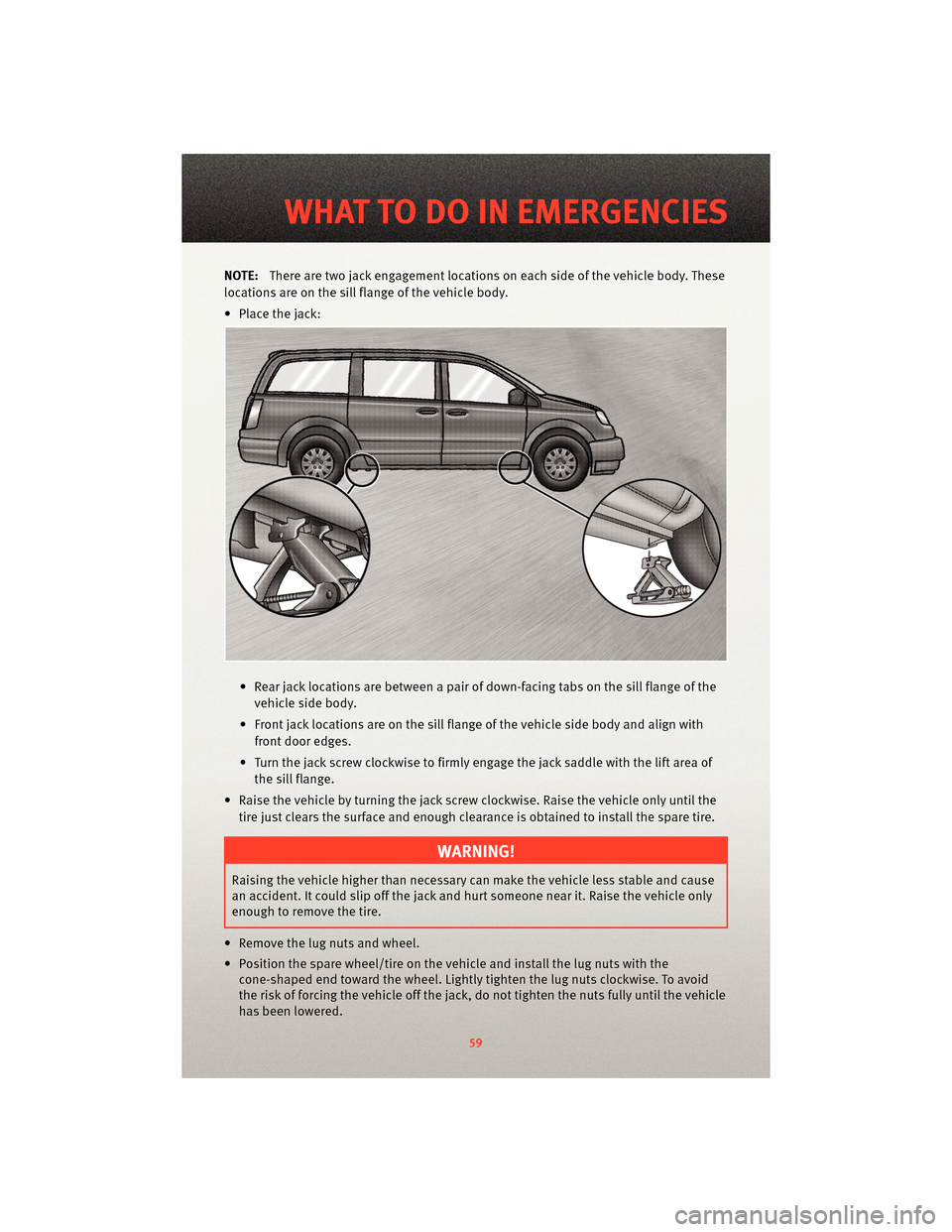
NOTE:There are two jack engagement locations on each side of the vehicle body. These
locations are on the sill flange of the vehicle body.
• Place the jack:
• Rear jack locations are between a pair of down-facing tabs on the sill flange of thevehicle side body.
• Front jack locations are on the sill flange of the vehicle side body and align with front door edges.
• Turn the jack screw clockwise to firmly engage the jack saddle with the lift area of the sill flange.
• Raise the vehicle by turning the jack screw clockwise. Raise the vehicle only until the tire just clears the surface and enough clearance is obtained to install the spare tire.
WARNING!
Raising the vehicle higher than necessary can make the vehicle less stable and cause
an accident. It could slip off the jack and hurt someone near it. Raise the vehicle only
enough to remove the tire.
• Remove the lug nuts and wheel.
• Position the spare wheel/tire on the vehicle and install the lug nuts with the cone-shaped end toward the wheel. Lightly tight en the lug nuts clockwise. To avoid
the risk of forcing the vehicle off the jack, do not tighten the nuts fully until the vehicle
has been lowered.
59
WHAT TO DO IN EMERGENCIES
Page 62 of 88
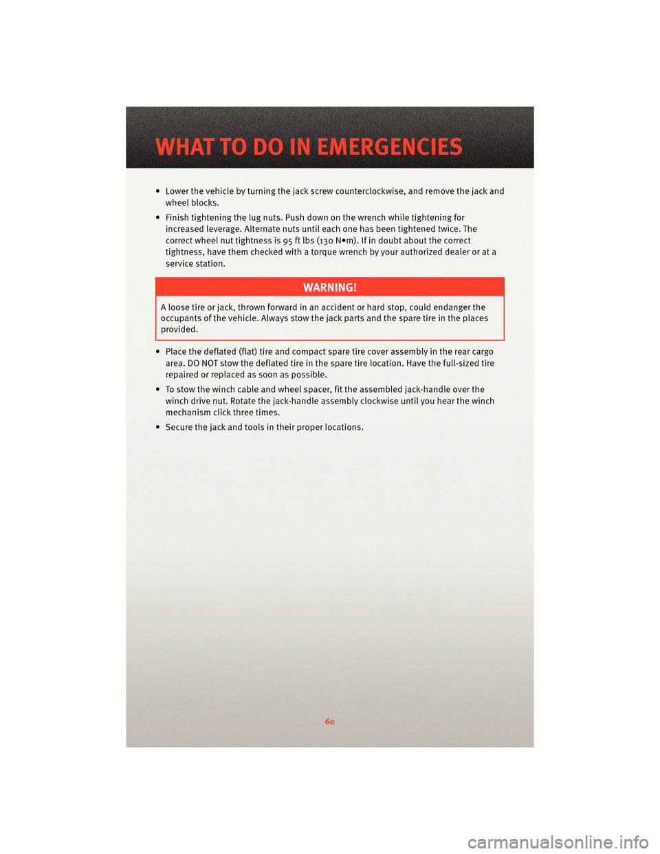
• Lower the vehicle by turning the jack screw counterclockwise, and remove the jack andwheel blocks.
• Finish tightening the lug nuts. Push do wn on the wrench while tightening for
increased leverage. Alternate nuts until each one has been tightened twice. The
correct wheel nut tightness is 95 ft lbs (130 N•m). If in doubt about the correct
tightness, have them checked with a tor que wrench by your authorized dealer or at a
service station.
WARNING!
A loose tire or jack, thrown forward in an accident or hard stop, could endanger the
occupants of the vehicle. Always stow the jack parts and the spare tire in the places
provided.
• Place the deflated (flat) tire and compact spare tire cover assembly in the rear cargo area. DO NOT stow the deflated tire in the spare tire location. Have the full-sized tire
repaired or replaced as soon as possible.
• To stow the winch cable and wheel spacer, fit the assembled jack-handle over the winch drive nut. Rotate the jack-handle as sembly clockwise until you hear the winch
mechanism click three times.
• Secure the jack and tools in their proper locations.
WHAT TO DO IN EMERGENCIES
60
Page 66 of 88
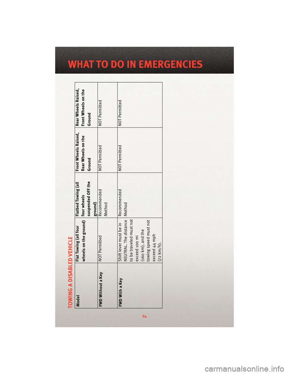
TOWING A DISABLED VEHICLEModelFlat Towing (all four
wheels on the ground)Flatbed Towing (all
four wheels
suspended OFF the
ground)Front Wheels Raised,
Rear Wheels on the
Ground
Rear Wheels Raised,
Front Wheels on the
Ground
FWD Without a Key NOT Permitted Recommended
MethodNOT Permitted NOT Permitted
FWD With a Key Shift lever must be in
NEUTRAL. The distance
to be traveled must not
exceed 100 mi
(160 km), and the
towing speed must not
exceed 44 mph
(72 km/h).Recommended
Method
NOT Permitted NOT Permitted
64
WHAT TO DO IN EMERGENCIES
Page 74 of 88
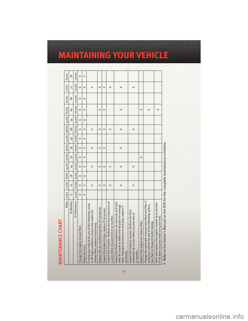
MAINTENANCE CHART
Miles:
6,000 12,000 18,000 24,000 30,000 36,000 42,000 48,000 54,000 60,000 66,000 72,000 78,000
Or Months: 6 12 18 24 30 36 42 48 54 60 66 72 78
Or Kilometers:
10,000 20,000 30,000 40,000 50,000 60,000 70,000 80,000 90,000 100,000 110,000 120,000 130,000
Change the engine oil and filter. XXXXXXXXX X X X X
Rotatethetires. XXXXXXXXX X X X X
If using your vehicle for any of the following: dusty
or off-road conditions. Inspect the engine air
cleaner filter; replace if necessary. XXXX X
Replace the air conditioning filter (if equipped). X X X X X X
Inspect the brake linings; replace if necessary. X X X X X X
Inspect the CV joints. Perform the first inspection at
12,000 miles (20,000 km) or 12 months. XX X X
Inspect the front suspe nsion, tie rod ends and boot
seals for cracks or leaks and all parts for damage,
wear, improper looseness or end play; replace if
necessary. XXXX X X
Inspect the exhaust system. Perform the first
inspection at 12,000 miles (20,000 km) or
12 months. XX X X
Replace the engine air cleaner filter. X X
Change the autom atic transmissionfluid and filter if
using your vehicle for any of the following: police,
taxi, fleet or frequent trailer towing. X
Flush and replace the engine coolant at 60 months
if not done 102,000 miles (170,000 km). X• Refer to the Owner's Manual on the DVD for the complete maintenance schedule.
72
MAINTAINING YOUR VEHICLE
Page 77 of 88
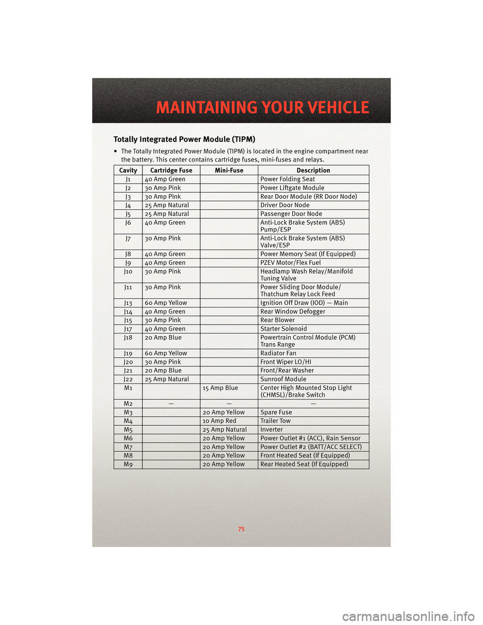
TotallyIntegrated Power Module (TIPM)
• The Totally Integrated Power Module (TIPM) is located in the engine compartment near
the battery. This center contains cartridge fuses, mini-fuses and relays.
Cavity Cartridge Fuse Mini-Fuse Description
J1 40 Amp Green Power Folding Seat
J2 30 Amp Pink Power Liftgate Module
J3 30 Amp Pink Rear Door Module (RR Door Node)
J4 25 Amp Natural Driver Door Node
J5 25 Amp Natural Passenger Door Node
J6 40 Amp Green Anti-Lock Brake System (ABS)
Pump/ESP
J7 30 Amp Pink Anti-Lock Brake System (ABS)
Valve/ESP
J8 40 Amp Green Power Memory Seat (If Equipped)
J9 40 Amp Green PZEV Motor/Flex Fuel
J10 30 Amp Pink Headlamp Wash Relay/Manifold
Tuning Valve
J11 30 Amp Pink Power Sliding Door Module/
Thatchum Relay Lock Feed
J13 60 Amp Yellow Ignition Off Draw (IOD) — Main
J14 40 Amp Green Rear Window Defogger
J15 30 Amp Pink Rear Blower
J17 40 Amp Green Starter Solenoid
J18 20 Amp Blue Powertrain Control Module (PCM)
Trans Range
J19 60 Amp Yellow Radiator Fan
J20 30 Amp Pink Front Wiper LO/HI
J21 20 Amp Blue Front/Rear Washer
J22 25 Amp Natural Sunroof Module
M1 15 Amp Blue Center High Mounted Stop Light
(CHMSL)/Brake Switch
M2 — — —
M3 20 Amp Yellow Spare Fuse
M4 10 Amp Red Trailer Tow
M5 25 Amp Natural Inverter
M6 20 Amp Yellow Power Outlet #1 (ACC), Rain Sensor
M7 20 Amp Yellow Power Outlet #2 (BATT/ACC SELECT)
M8 20 Amp Yellow Front Heated Seat (If Equipped)
M9 20 Amp Yellow Rear Heated Seat (If Equipped)
75
MAINTAINING YOUR VEHICLE