tow DODGE GRAND CARAVAN 2010 5.G User Guide
[x] Cancel search | Manufacturer: DODGE, Model Year: 2010, Model line: GRAND CARAVAN, Model: DODGE GRAND CARAVAN 2010 5.GPages: 88, PDF Size: 13.56 MB
Page 2 of 88
IMPORTANT: This User Guide is i\fte\fded to
f\bmili\brize you with the import\b\ft fe\btures of
your vehicle. The DVD e\fclosed co\ft\bi\fs your
Ow\fer’s M\b\fu\bl, N\bvig\btio\f/Medi\b Ce\fter
M\b\fu\bls, W\brr\b\fty Booklets, Tire W\brr\b\fty \b\fd
24-Hour Towi\fg Assist\b\fce (\few vehicles
purch\bsed i\f the U.S.) or Ro\bdside Assist\b\fce
(\few vehicles purch\bsed i\f C\b\f\bd\b) i\f electro\fic
form\bt. We hope you fi\fd it useful. If you \bre the
first registered ow\fer of your vehicle, you m\by
obt\bi\f \b pri\fted copy of the Ow\fer’s M\b\fu\bl,
N\bvig\btio\f/Medi\b Ce\fter M\b\fu\bls or W\brr\b\fty
Booklet by c\blli\fg 1-800-423-6343 (U.S.) or
1-800-387-1143 (C\b\f\bd\b) or by co\ft\bcti\fg your
de\bler. Repl\bceme\ft DVD kits m\by be purch\bsed
by visiti\fg www.tech\buthority.com.
Copyright © 2010 Chrysler Group LLC.
Page 3 of 88
INTRODUCTION/WELCOME
WELCOME FROM CHRYSLER GROUP LLC.. 2
CONTROLS AT A GLANCE
DRIVER COCKPIT.............. 4
INSTRUMENT CLUSTER ..........6
GETTING STARTED
KEYFOB...................8
THEFT ALARM................ 9
SEATBELT ................. 9
CHILD RESTRAINTS .............10
FRONTSEATS................13
HEATEDSEATS...............15
TILT STEERING COLUMN ..........17
ADJUSTABLEPEDALS ...........17
PROGRAMMABLEFEATURES .......18
OPERATING YOUR VEHICLE
TURN SIGNAL/WIPER/WASHER/HIGH
BEAMLEVER ............... 20
HEADLIGHT SWITCH AND HALO LIGHT
SWITCH...................21
SPEED CONTROL LEVER ......... 22
ELECTRONIC RANGE SELECTION (ERS)...23
MANUAL CLIMATE CONTROLS .......23
FRONT THREE ZONE MANUAL CLIMATE
CONTROLS ................ 24
FRONT THREE ZONE AUTOMATIC
TEMPERATURE CONTROLS (ATC) .....25
PARKSENSE
®REAR PARK ASSIST .....27
PARKVIEW®REAR BACK-UP CAMERA . . .27
REAR CROSS PATH WITH BLIND SPOT
MONITORING ............... 28
POWER SLIDING SIDE DOORS ...... 28
STOW 'N GO
®SEATING ......... 29
SWIVEL N’ GO™ SEATING WITH TABLE . 30
THIRD ROW POWER RECLINER .......31
POWERLIFTGATE..............32
POWERSUNROOF .............32
WIND BUFFETING ..............33
ELECTRONICS
NON-TOUCH-SCREENRADIOS.......34
TOUCH-SCREENRADIOS......... 36
REMOTE AUDIO CONTROLS ....... 40
VIDEO ENTERTAINMENT
SYSTEM(VES)™ ............. 40
UNIVERSAL CONSUMER INTERFACE . . . 42
ELECTRONIC VEHICLE INFORMATION
CENTER (EVIC) ...............43 UNIVERSAL GARAGE DOOR OPENER
(HOMELINK
®) ...............43
POWERINVERTER .............45
POWER OUTLETS ..............45
Uconnect™ Phone ............ 46
VOICECOMMAND ............ 48
UTILITY
IN-FLOOR STORAGE – STOW N’ GO®.. 49
TRAILER TOWING WEIGHTS (MAXIMUM
TRAILER WEIGHT RATINGS) ........50
RECREATIONAL TOWING (BEHIND
MOTORHOME, ETC.) ............51
BRAKE/TRANSMISSION INTERLOCK
MANUAL OVERRIDE ............51
WHAT TO DO IN EMERGENCIES
24-HOUR TOWINGASSISTANCE -
U.S. ONLY .................52
INSTRUMENT CLUSTER WARNING
LIGHTS ...................52
IF YOUR ENGINE OVERHEATS .......55
JACKINGANDTIRECHANGING.......56
JUMP-STARTING ..............61
TOWINGADISABLEDVEHICLE...... 64
FREEING A STUCK VEHICLE ........65
EVENT DATA RECORDER (EDR) ......65
MAINTAINING YOUR VEHICLE
OPENING THE HOOD............67
ADDINGFUEL................67
ENGINE COMPARTMENT ......... 69
FLUIDS AND CAPACITIES ..........71
MAINTENANCE CHART ...........72
FUSES....................74
TIREPRESSURES..............77
WHEEL AND WHEEL TRIM CARE ......78
EXTERIOR BULBS ..............78
CONSUMER ASSISTANCE
CHRYSLER GROUP LLC CUSTOMER
CENTER...................79
CHRYSLER CANADA INC. CUSTOMER
CENTER...................79
ASSISTANCE FOR THE HEARING
IMPAIRED..................79
PUBLICATIONS ORDERING .........79
REPORTING SAFETY DEFECTS IN
THE 50 UNITED STATES AND
WASHINGTON, D.C. ........... 80
TIRE WARRANTY ............. 80
MOPAR ACCESSORIES
MOPAR®ACCESSORIES..........83
TABLE OF CONTENTS
Page 24 of 88
SPEED CONTROL LEVER
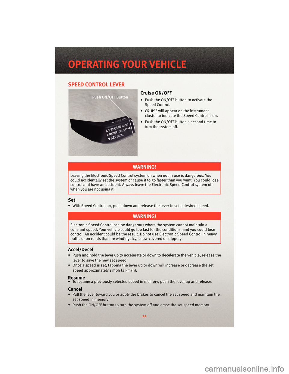
Cruise ON/OFF
• Push the ON/OFF button to activate theSpeed Control.
• CRUISE will appear on the instrument cluster to indicate the Speed Control is on.
• Push the ON/OFF button a second time to turn the system off.
WARNING!
Leaving the Electronic Speed Control system on when not in use is dangerous. You
could accidentally set the system or cause it to go faster than you want. You could lose
control and have an accident. Always leave the Electronic Speed Control system off
when you are not using it.
Set
• With Speed Control on, push down and release the lever to set a desired speed.
WARNING!
Electronic Speed Control can be dangerous where the system cannot maintain a
constant speed. Your vehicle could go too fast for the conditions, and you could lose
control. An accident could be the result. Do not use Electronic Speed Control in heavy
traffic or on roads that are winding, icy, snow-covered or slippery.
Accel/Decel
• Push and hold the lever up to accelerate or down to decelerate the vehicle; release the
lever to save the new set speed.
• Once a speed is set, tapping the lever up or down will increase or decrease the set speed approximately 1 mph (2 km/h).
Resume• To resume a previously selected speed in memory, push the lever up and release.
Cancel
• Pull the lever toward you or apply the brakes to cancel the set speed and maintain theset speed in memory.
• Push the ON/OFF button to turn the system off and erase the set speed memory.
OPERATING YOUR VEHICLE
22
Page 30 of 88
REAR CROSS PATH WITH BLIND SPOT MONITORING
• The Blind Spot Monitoring (BSM) system warning light, located in the outside mirrors,
will illuminate if a vehicle moves into a blind spot zone.
• The BSM system can also be configured to sound an audible (chime) alert and mute the radio to notify you of objects that have entered the detection zones.
• Refer to your owner's manual on the DVD for further details.
POWER SLIDING SIDE DOORS
Automatic/Manual Operation
• The power sliding door may be opened or closed manually or by using the buttons on the Key Fob, overhead console switch, or rear door switch.
• Pulling the inside or outside power sliding door handle will also power open the power sliding doors.
Sliding Side Door Child Protection Lock
• When this system is engaged, the inside manual door handle will not open the slidingdoor even though the inside door lock is in the unlocked position.
• To engage the Child Protection Door Lock, open the sliding side door. Slide the child protection door lock control, located on the re ar of the sliding door, inward (toward
the vehicle) to engage.
• Repeat these steps on the opposite sliding door.
OPERATING YOUR VEHICLE
28
Page 31 of 88
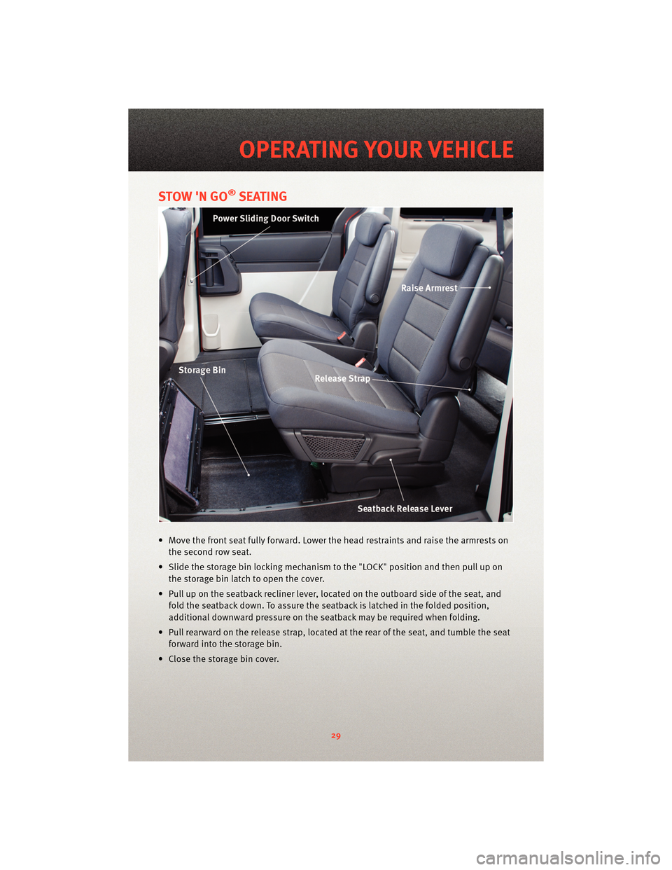
STOW 'N GO®SEATING
• Move the front seat fully forward. Lower the head restraints and raise the armrests onthe second row seat.
• Slide the storage bin locking mechanism to the "LOCK" position and then pull up on the storage bin latch to open the cover.
• Pull up on the seatback recliner lever, located on the outboard side of the seat, and fold the seatback down. To assure the seatback is latched in the folded position,
additional downward pressure on the seatback may be required when folding.
• Pull rearward on the release strap, located at the rear of the seat, and tumble the seat forward into the storage bin.
• Close the storage bin cover.
29
OPERATING YOUR VEHICLE
Page 33 of 88
To Remove The Seats
• Remove any obstructions from the floor behind the seat, and stow the third row seat.
• Pull up on the release bar located at the bottom front edge of the swivel seat.
• From behind the seat, lift up on the rear of the seat cushion while pulling the seat in arearward direction.
• Remove the seat from the vehicle through the liftgate. Rollers are part of the seat frame and will ease the removal process.
• Lower the release handle located at the bottom front edge of the seat.
THIRD ROW POWER RECLINER
• The power recline feature, located on the side of the seat cushion, adjusts the seatback angle forward/rea rward for occupant comfort.
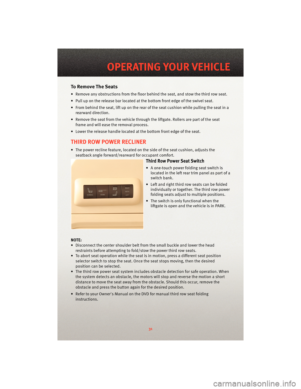
Third Row Power Seat Switch
• A one-touch power folding seat switch is
located in the left rear trim panel as part of a
switch bank.
• Left and right third row seats can be folded individually or together. The third row power
folding seats adjust to multiple positions.
• The switch is only functional when the liftgate is open and the vehicle is in PARK.
NOTE:
• Disconnect the center shoulder belt from the small buckle and lower the head restraints before attempting to fold/stow the power third row seats.
• To abort seat operation while the seat is in motion, press a different seat position selector switch to stop the seat. Once the seat stops moving, then the desired
position can be selected.
• The third row power seat system includes obstacle detection for safe operation. When the system detects an obstacle, the motors will stop and reverse the motion a short
distance to move the seat away from the obstacle. Should this occur, remove the
obstacle and press the button again for the desired position.
• Refer to your Owner's Manual on the DVD for manual third row seat folding instructions.
31
OPERATING YOUR VEHICLE
Page 51 of 88
IN-FLOOR STORAGE –STOW
N’ GO®
Second Row Seat Storage Bins
• Storage bins are located in the floor in front of the second row seats that can
be used when the second row seat is
in the upright position. Pull up on the
storage bin latch to open the cover.
Slide the storage bin locking
mechanism to the "Lock" position to
allow greater access to the storage
bin.
WARNING!
In an accident, serious injury could
result if the seat storage bin covers
are not properly latched. DO NOT
drive the vehicle with the storage bin
covers open. Keep the storage bin
covers closed and latched while the
vehicle is in motion. DO NOT use a
storage bin latch as a tie down.
Cargo Area Storage
• The liftgate sill plate has a raised line
with the statement “Load To This
Line”. This line indicates how far
rearward cargo can be placed without
interfering with liftgate closing.
49
UTILITY
Page 52 of 88
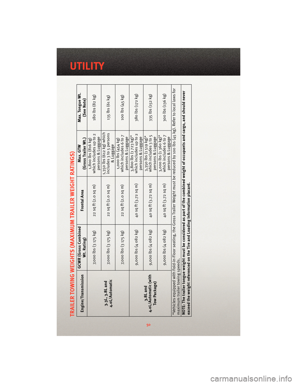
TRAILER TOWING WEIGHTS (MAXIMUM TRAILER WEIGHT RATINGS)Engine/Transmission GCWR (Gross Combined
Wt. Rating) Frontal Area Max. GTW
(Gross Trailer Wt.) Max. Tongue Wt.
(See Note)
3.3L, 3.8L and
4.0L/Automatic 7,000 lbs (3 175 kg) 22 sq ft (2.0 sq m)
1,800 lbs (816 kg)
which includes up to 2 persons & Luggage 180 lbs (82 kg)
7,000 lbs (3 175 kg) 22 sq ft (2.0 sq m) 1,350 lbs (612 kg) which
includes 3 to 5 persons & Luggage 135lbs(61kg)
7,000 lbs (3 175 kg) 22 sq ft (2.0 sq m) 1,000 lbs (454 kg)
which includes 6 to 7 persons & Luggage 100 lbs (45 kg)
3.8L and
4.0L/Automatic (with
Tow Package) 9,000 lbs (4 082 kg) 40 sq ft (3.72 sq m)
3,800 lbs (1 723 kg)*
which includes up to 2 persons & Luggage 380 lbs (172 kg)
9,000 lbs (4 082 kg) 40 sq ft (3.72 sq m) 3,350 lbs (1 519 kg)*
which includes 3 to 5 persons & Luggage 335 lbs (152 kg)
9,000 lbs (4 082 kg) 40 sq ft (3.72 sq m) 3,000 lbs (1 360 kg)*
which includes 6 to 7 persons & Luggage 300 lbs (136 kg)
*Vehicles equipped with Fold-in-Floor seating, the Gross Trailer Weight must be reduced by 100 lbs (45 kg). Refer to local laws for
maximum trailer towing speeds.
NOTE: The trailer tongue weight must be considered as part of the combined weight of occupants and cargo, and should never
exceed the weight referenced on the Tire and Loading Information placard.
50
UTILITY
Page 53 of 88
RECREATIONAL TOWING
(BEHIND MOTORHOME,
ETC.)
CAUTION!
Towing this vehicle behind another
vehicle (flat-towing with all four
wheels on the ground) is not
recommended.
NOTE: If the vehicle requires towing,
make sure all four wheels are off the
ground.
BRAKE/TRANSMISSION
INTERLOCK MANUAL
OVERRIDE
• The manual override may be used in the event that the shift lever should
fail to move from PARK with the Key
Fob in the ON/RUN position and the
brake pedal pressed.
• To operate the shift lock manual override, perform the following steps: • Remove the cover located to the
top right of the shift lever in the
instrument panel.
• The override can be activated by pressing the white-colored tab,
which can be accessed through the
hole in the instrument panel.
• While the override is pressed, the shift lever can be moved out of the
PARK position without pressing the
brake pedal. After operation, return
the cover to its original position.
• Have your vehicle inspected by your local authorized dealer immediately if
the shift lock manual override has
been used.
NOTE: If a malfunction occurs, the
system will trap the Key Fob in the
ignition cylinder to warn you that this
safety feature is inoperable. The engine
can be started and stopped, but the Key
Fob cannot be removed until you obtain
service.
51
UTILITY
Page 54 of 88
24-HOUR TOWING ASSISTANCE - U.S. ONLY
• Dial toll-free 1-800-521-2779 or 1-800-363-4869 for Canadian residents.
• Provide your name, vehicle identification number and license plate number.
• Provide your location, including telephone number, from which you are calling.
• Briefly describe the nature of the problem and answer a few simple questions.
• You will be given the name of the service provider and an estimated time of arrival. Ifyou feel you are in an “unsafe situation”, please let us know. With your consent, we
will contact local police or safety authorities.
INSTRUMENT CLUSTER WARNING LIGHTS
- Electronic Stability Program (ESP) Indicator Light
• If this indicator light flashes during acceleration, apply as little throttle as possible.While driving, ease up on the accelerator. Adapt your speed and driving to the
prevailing road conditions. To improve the vehicle's traction when starting off in deep
snow, sand or gravel, it may be desirable to switch the ESP system off.
- Tire Pressure Monitoring System (TPMS) Light
• Each tire, including the spare (if provided), should be checked monthly, when cold and inflated to the inflation pressure recommended by the vehicle manufacturer on
the vehicle placard or tire inflation pressure label. (If your vehicle has tires of a
different size than the size indicated on the v ehicle placard or tire inflation pressure
label, you should determine the proper tire inflation pressure for those tires.)
• As an added safety feature, your vehicle has been equipped with a Tire Pressure Monitoring System (TPMS) that illuminates a low tire pressure telltale when one or
more of your tires is significantly under-inflat ed. Accordingly, when the low tire
pressure telltale illuminates, you should stop and check your tires as soon as
possible, and inflate them to the proper pressure. Driving on a significantly
under-inflated tire causes the tire to overheat and can lead to tire failure.
Under-inflation also reduces fuel efficiency and tire tread life, and may affect the
vehicle’s handling and stopping ability.
• Please note that the TPMS is not a subs titute for proper tire maintenance, and it is the
driver’s responsibility to maintain correct tire pressure, even if under-inflation has not
reached the level to trigger illumination of the TPMS low tire pressure telltale.
• Your vehicle has also been equipped with a TPMS malfunction indicator to indicate
when the system is not operating properly. The TPMS malfunction indicator is
combined with the low tire pressure telltale. When the system detects a malfunction,
the telltale will flash for approximately one minute and then remain continuously
illuminated. This sequence will continue upon subsequent vehicle start-ups as long as
the malfunction exists.
WHAT TO DO IN EMERGENCIES
52