tire pressure DODGE GRAND CARAVAN 2015 5.G Service Manual
[x] Cancel search | Manufacturer: DODGE, Model Year: 2015, Model line: GRAND CARAVAN, Model: DODGE GRAND CARAVAN 2015 5.GPages: 703, PDF Size: 19.83 MB
Page 568 of 703
from the vehicle or tire and wheel components. Once
the sealant dries, it can easily be peeled off and
properly discarded.
•For optimum performance, make sure the valve stem
on the wheel is free of debris before connecting the Tire
Service Kit.
•You can use the Tire Service Kit air pump to inflate
bicycle tires. The kit also comes with two needles,
located in the Accessory Storage Compartment (on the
bottom of the air pump) for inflating sport balls, rafts,
or similar inflatable items. However, use only the Air
Pump Hose (7) and make sure the Mode Select Knob
(5) is in the Air Mode when inflating such items to
avoid injecting sealant into them. The Tire Service Kit
Sealant is only intended to seal punctures less than¼”
(6 mm) diameter in the tread of your vehicle.
•Do not lift or carry the Tire Service Kit by the hoses.
WARNING!
•Do not attempt to seal a tire on the side of the
vehicle closest to traffic. Pull far enough off the
road to avoid the danger of being hit when using
the Tire Service Kit.
•Do not use Tire Service Kit or drive the vehicle
under the following circumstances:
– If the puncture in the tire tread is approximately
1/4” (6 mm) or larger.
– If the tire has any sidewall damage.
– If the tire has any damage from driving with
extremely low tire pressure.
– If the tire has any damage from driving on a flat
tire.
– If the wheel has any damage.
– If you are unsure of the condition of the tire or
the wheel.
(Continued)
566 WHAT TO DO IN EMERGENCIES
Page 571 of 703
NOTE:Sealant may leak out through the puncture in the
tire.
If the sealant (white fluid) does not flow within0–10
seconds through the Sealant Hose (6):
1. Press the Power Button (4) to turn Off the Tire Service
Kit. Disconnect the Sealant Hose (6) from the valve
stem. Make sure the valve stem is free of debris.
Reconnect the Sealant Hose (6) to the valve stem.
Check that the Mode Select Knob (5) is in the Sealant
Mode position and not Air Mode. Press the Power
Button (4) to turn On the Tire Service Kit.
2. Connect the Power Plug (8) to a different 12 Volt
power outlet in your vehicle or another vehicle, if
available. Make sure the engine is running before
turning ON the Tire Service Kit.
3. The Sealant Bottle (1) may be empty due to previous
use. Call for assistance.
NOTE:If the Mode Select Knob (5) is on Air Mode and
the pump is operating, air will dispense from the Air
Pump Hose (7) only, not the Sealant Hose (6).
If the sealant (white fluid) does flow through the
Sealant Hose (6):
1. Continue to operate the pump until sealant is no
longer flowing through hose (typically takes 30 - 70
seconds). As the sealant flows through the Sealant
Hose (6), the Pressure Gauge (3) can read as high as 70
psi (4.8 Bar). The Pressure Gauge (3) will decrease
quickly from approximately 70 psi (4.8 Bar) to the
actual tire pressure when the Sealant Bottle (1) is
empty.
2. The pump will start to inject air into the tire immedi-
ately after the Sealant Bottle (1) is empty. Continue to
operate the pump and inflate the tire to the pressure
indicated on the tire pressure label on the driver-side
6
WHAT TO DO IN EMERGENCIES 569
Page 572 of 703
latch pillar (recommended pressure). Check the tire
pressure by looking at the Pressure Gauge (3).
If the tire does not inflate to at least 26 psi (1.8 Bar)
pressure within 15 minutes:
•The tire is too badly damaged. Do not attempt to drive
the vehicle further. Call for assistance.
NOTE:If the tire becomes over-inflated, press the Defla-
tion Button to reduce the tire pressure to the recom-
mended inflation pressure before continuing.
If the tire inflates to the recommended pressure or is at
least 26 psi (1.8 Bar) pressure within 15 minutes:
1. Press the Power Button (4) to turn off the Tire Service
Kit.
2. Remove the Speed Limit sticker from the top of the
Sealant Bottle (1) and place the sticker on the instru-
ment panel.
3. Immediately disconnect the Sealant Hose (6) from the
valve stem, reinstall the cap on the fitting at the end of
the hose, and place the Tire Service Kit in the vehicle
storage location. Quickly proceed to (D) “Drive Ve-
hicle.”
CAUTION!
•The metal end fitting from Power Plug (8) may get
hot after use, so it should be handled carefully.
•Failure to reinstall the cap on the fitting at the end
of the Sealant Hose (6) can result in sealant con-
tacting your skin, clothing, and the vehicle’s inte-
rior. It can also result in sealant contacting internal
Tire Service Kit components which may cause
permanent damage to the kit.
570 WHAT TO DO IN EMERGENCIES
Page 573 of 703
(D) Drive Vehicle:
Immediately after injecting sealant and inflating the tire,
drive the vehicle 5 miles (8 km) or 10 minutes to ensure
distribution of the Tire Service Kit Sealant within the tire.
Do not exceed 55 mph (90 km/h).
WARNING!
Tire Service Kit is not a permanent flat tire repair.
Have the tire inspected and repaired or replaced after
using Tire Service Kit. Do not exceed 55 mph (90
km/h) until the tire is repaired or replaced. Failure to
follow this warning can result in injuries that are
serious or fatal to you, your passengers, and others
around you.
(E) After Driving:
Pull over to a safe location. Refer to “Whenever You Stop
to Use Tire Service Kit” before continuing.
1. Push in the Mode Select Knob (5) and turn to the Air
Mode position.
2. Uncoil the power plug and insert the plug into the
vehicle’s 12 Volt power outlet.
3. Uncoil the Air Pump Hose (7) (black in color) and
screw the fitting at the end of hose (7) onto the valve
stem.
4. Check the pressure in the tire by reading the Pressure
Gauge (3).
If tire pressure is less than 19 psi (1.3 Bar):
The tire is too badly damaged. Do not attempt to drive
the vehicle further. Call for assistance.
6
WHAT TO DO IN EMERGENCIES 571
Page 574 of 703
If the tire pressure is 19 psi (1.3 Bar) or higher:
1. Press the Power Button (4) to turn on Tire Service Kit
and inflate the tire to the pressure indicated on the tire
and loading information label on the driver-side door
opening.
NOTE:If the tire becomes over-inflated, press the Defla-
tion Button to reduce the tire pressure to the recom-
mended inflation pressure before continuing.
2. Disconnect the Tire Service Kit from the valve stem,
reinstall the cap on the valve stem and unplug from 12
Volt outlet.
3. Place the Tire Service Kit in its proper storage area in
the vehicle.
4. Have the tire inspected and repaired or replaced at the
earliest opportunity at an authorized dealer or tire
service center.
5. Remove the Speed Limit sticker from the instrument
panel after the tire has been repaired.
6. Replace the Sealant Bottle (1) and Sealant Hose (6)
assembly at your authorized dealer as soon as pos-
sible. Refer to (F) “Sealant Bottle and Hose Replace-
ment”.
NOTE:When having the tire serviced, advise the autho-
rized dealer or service center that the tire has been sealed
using the Tire Service Kit.
(F) Sealant Bottle And Hose Replacement:
1. Uncoil the Sealant Hose (6) (clear in color).
2. Locate the round Sealant Bottle release button in the
recessed area under the sealant bottle.
3. Press the Sealant Bottle release button. The Sealant
Bottle (1) will pop up. Remove the bottle and dispose
of it accordingly.
572 WHAT TO DO IN EMERGENCIES
Page 592 of 703
NOTE:Refer to the “Spare Tire Tools” section for in-
structions on assembling the T-handle.
12. Stow the jack, jack handle and winch handle tools
back in the stowage compartment.
13. Check the compact spare tire pressure as soon as
possible. Correct the tire pressure, as required.
Securing The Compact Spare Tire
1. Assemble the winch handle extensions to form a
T-handle and fit the winch T-handle over the drive
nut. Rotate the nut to the left until the winch mecha-
nism stops turning freely. This will allow enough slack
in the cable to allow you to pull the wheel spacer out
from under the vehicle.
WARNING!
A loose compact spare tire/cover assembly, thrown
forward in a collision or hard stop could endanger
the occupants of the vehicle. Always stow the com-
pact spare tire with the cover assembly in the place
provided.
CAUTION!
The winch mechanism is designed for use with the
winch T-handle only. Use of an air wrench or other
power tools is not recommended and can damage the
winch.
2. Assemble the winch handle extensions to form the
spare tire hook, and pull the wheel spacer from under
the vehicle.
590 WHAT TO DO IN EMERGENCIES
Page 626 of 703
with water as directed on the container, aids cleaning
action, reduces the freezing point to avoid line clogging,
and is not harmful to paint or trim.
Cooling System
WARNING!
•When working near the radiator cooling fan,
disconnect the fan motor lead or turn the ignition
switch to the OFF position. The fan is temperature
controlled and can start at anytime the ignition
switch is in the ON position.
•You or others can be badly burned by hot engine
coolant (antifreeze) or steam from your radiator. If
you see or hear steam coming from under the hood,
do not open the hood until the radiator has had
time to cool. Never try to open a cooling system
pressure cap when the radiator is hot.
Coolant Checks
Check the engine coolant (antifreeze) protection every 12
months (before the onset of freezing weather, where
applicable). If the engine coolant (antifreeze) is dirty, the
system should be drained, flushed, and refilled with
fresh OAT coolant (conforming to MS-12106) only by an
authorized dealer. Check the front of the A/C condenser
for any accumulation of bugs, leaves, etc. If dirty, clean by
gently spraying water from a garden hose vertically
down the face of the condenser.
Check the coolant recovery bottle tubing for brittle rub-
ber, cracking, tears, cuts and tightness of the connection
at the bottle and radiator. Inspect the entire system for
leaks.
With the engine at normal operating temperature (but
not running), check the cooling system pressure cap for
proper vacuum sealing by draining a small amount of
engine coolant (antifreeze) from the radiator drain cock.
624 MAINTAINING YOUR VEHICLE
Page 649 of 703
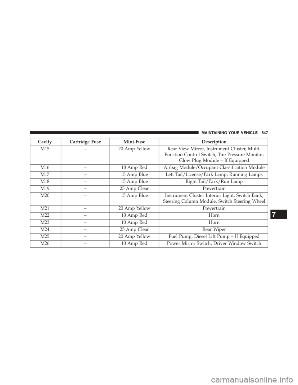
Cavity Cartridge Fuse Mini-FuseDescription
M15–20 Amp Yellow Rear View Mirror, Instrument Cluster, Multi-
Function Control Switch, Tire Pressure Monitor,
Glow Plug Module – If Equipped
M16–10 Amp Red Airbag Module/Occupant Classification Module
M17–15 Amp Blue Left Tail/License/Park Lamp, Running Lamps
M18–15 Amp BlueRight Tail/Park/Run Lamp
M19–25 Amp ClearPowertrain
M20–15 Amp Blue Instrument Cluster Interior Light, Switch Bank,
Steering Column Module, Switch Steering Wheel
M21–20 Amp YellowPowertrain
M22–10 Amp RedHorn
M23–10 Amp RedHorn
M24–25 Amp ClearRear Wiper
M25–20 Amp Yellow Fuel Pump, Diesel Lift Pump – If Equipped
M26–10 Amp Red Power Mirror Switch, Driver Window Switch
7
MAINTAINING YOUR VEHICLE 647
Page 665 of 703
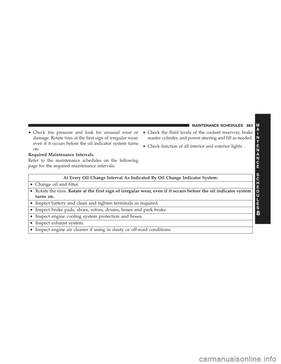
•Check tire pressure and look for unusual wear or
damage. Rotate tires at the first sign of irregular wear,
even if it occurs before the oil indicator system turns
on.
•Check the fluid levels of the coolant reservoir, brake
master cylinder, and power steering and fill as needed.
•Check function of all interior and exterior lights .
Required Maintenance Intervals.
Refer to the maintenance schedules on the following
page for the required maintenance intervals.
At Every Oil Change Interval As Indicated By Oil Change Indicator System:
•Change oil and filter.
•Rotate the tires.Rotate at the first sign of irregular wear, even if it occurs before the oil indicator system
turns on.
•Inspect battery and clean and tighten terminals as required.
•Inspect brake pads, shoes, rotors, drums, hoses and park brake.
•Inspect engine cooling system protection and hoses.
•Inspect exhaust system.
•Inspect engine air cleaner if using in dusty or off-road conditions.
8
MAINTENANCE
SCHEDULES
MAINTENANCE SCHEDULES 663
Page 682 of 703
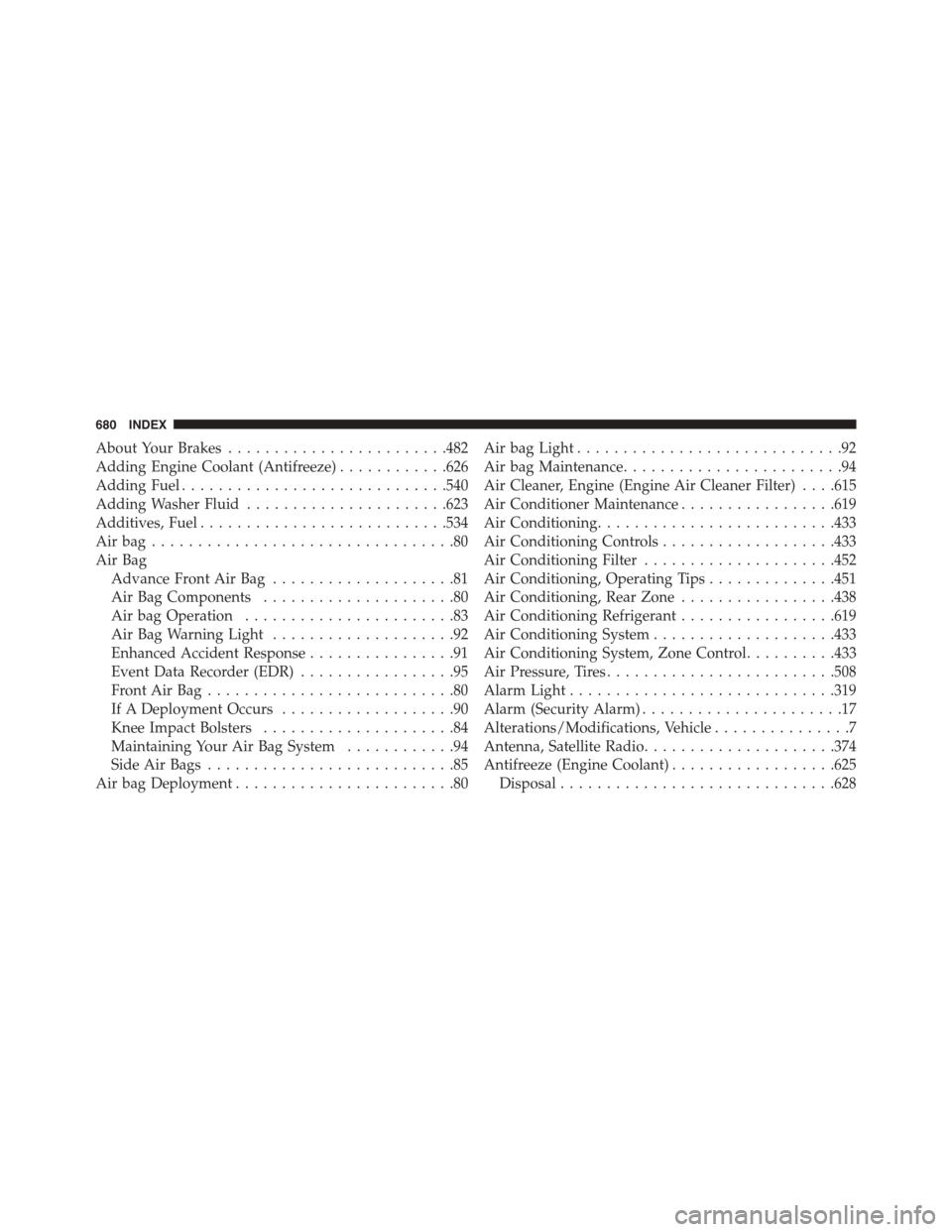
About Your Brakes........................482
Adding Engine Coolant (Antifreeze)............626
Adding Fuel.............................540
Adding Washer Fluid......................623
Additives, Fuel...........................534
Air bag . . . . . . . . . . . . . . . . . . . . . . . . . . . . . . . . .80
Air Bag
Advance Front Air Bag....................81
Air Bag Components.....................80
Air bag Operation.......................83
Air Bag Warning Light....................92
Enhanced Accident Response................91
Event Data Recorder (EDR).................95
Front Air Bag . . . . . . . . . . . . . . . . . . . . . . . . . . .80
If A Deployment Occurs...................90
Knee Impact Bolsters.....................84
Maintaining Your Air Bag System............94
Side Air Bags...........................85
Air bag Deployment........................80
Air bag Light.............................92
Air bag Maintenance........................94
Air Cleaner, Engine (Engine Air Cleaner Filter) . . . .615
Air Conditioner Maintenance.................619
Air Conditioning..........................433
Air Conditioning Controls...................433
Air Conditioning Filter.....................452
Air Conditioning, Operating Tips..............451
Air Conditioning, Rear Zone.................438
Air Conditioning Refrigerant.................619
Air Conditioning System....................433
Air Conditioning System, Zone Control..........433
Air Pressure, Tires.........................508
Alarm Light.............................319
Alarm (Security Alarm)......................17
Alterations/Modifications, Vehicle...............7
Antenna, Satellite Radio.....................374
Antifreeze (Engine Coolant)..................625
Disposal..............................628
680 INDEX