ECU DODGE GRAND CARAVAN 2015 5.G Workshop Manual
[x] Cancel search | Manufacturer: DODGE, Model Year: 2015, Model line: GRAND CARAVAN, Model: DODGE GRAND CARAVAN 2015 5.GPages: 703, PDF Size: 19.83 MB
Page 586 of 703
WARNING!(Continued)
•Only use the jack in the positions indicated and for
lifting this vehicle during a tire change.
•If working on or near a roadway, be extremely
careful of motor traffic.
•To assure that compact spare tires, flat or inflated,
are securely stowed, compact spares must be
stowed with the valve stem facing the ground.
CAUTION!
Do not attempt to raise the vehicle by jacking on
locations other than those indicated in the Jacking
Instructions for this vehicle.
NOTE:Refer to the “Compact Spare Tire” section of
“Tires – General Information” for information about the
compact spare tire, its use, and operation.
1. Loosen (but do not remove) the wheel lug nuts by
turning them to the left one turn while the wheel is
still on the ground.
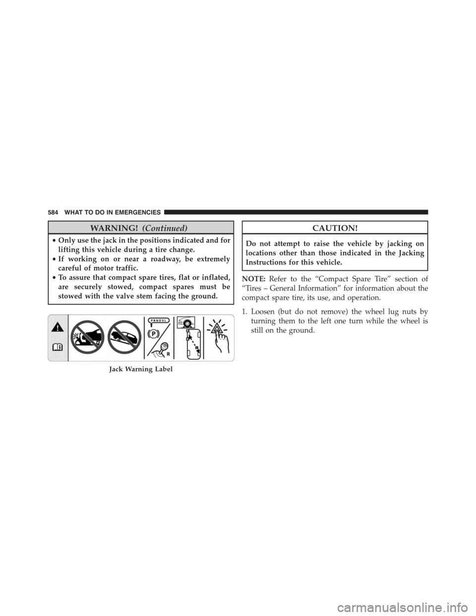
Jack Warning Label
584 WHAT TO DO IN EMERGENCIES
Page 589 of 703
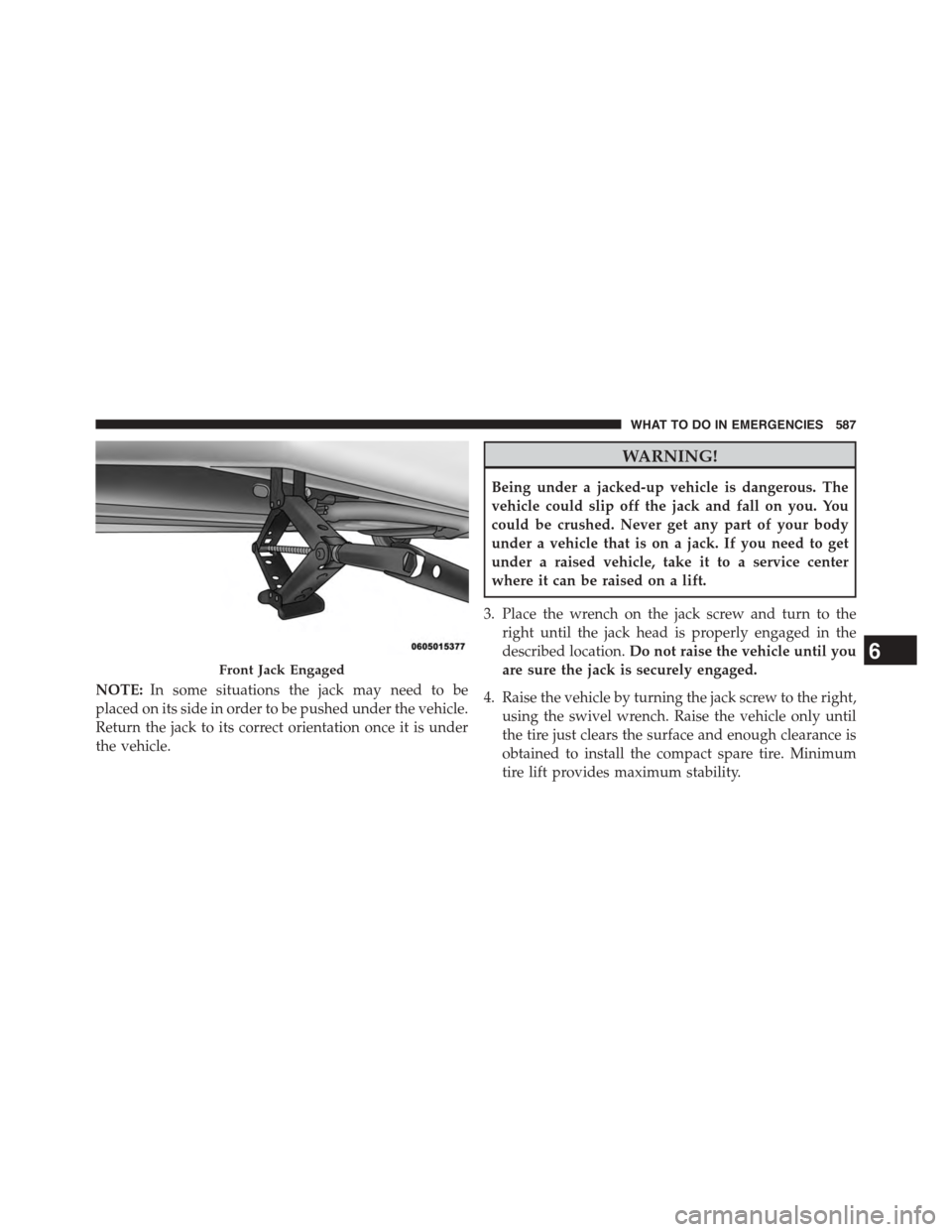
NOTE:In some situations the jack may need to be
placed on its side in order to be pushed under the vehicle.
Return the jack to its correct orientation once it is under
the vehicle.
WARNING!
Being under a jacked-up vehicle is dangerous. The
vehicle could slip off the jack and fall on you. You
could be crushed. Never get any part of your body
under a vehicle that is on a jack. If you need to get
under a raised vehicle, take it to a service center
where it can be raised on a lift.
3. Place the wrench on the jack screw and turn to the
right until the jack head is properly engaged in the
described location.Do not raise the vehicle until you
are sure the jack is securely engaged.
4. Raise the vehicle by turning the jack screw to the right,
using the swivel wrench. Raise the vehicle only until
the tire just clears the surface and enough clearance is
obtained to install the compact spare tire. Minimum
tire lift provides maximum stability.
Front Jack Engaged6
WHAT TO DO IN EMERGENCIES 587
Page 592 of 703
NOTE:Refer to the “Spare Tire Tools” section for in-
structions on assembling the T-handle.
12. Stow the jack, jack handle and winch handle tools
back in the stowage compartment.
13. Check the compact spare tire pressure as soon as
possible. Correct the tire pressure, as required.
Securing The Compact Spare Tire
1. Assemble the winch handle extensions to form a
T-handle and fit the winch T-handle over the drive
nut. Rotate the nut to the left until the winch mecha-
nism stops turning freely. This will allow enough slack
in the cable to allow you to pull the wheel spacer out
from under the vehicle.
WARNING!
A loose compact spare tire/cover assembly, thrown
forward in a collision or hard stop could endanger
the occupants of the vehicle. Always stow the com-
pact spare tire with the cover assembly in the place
provided.
CAUTION!
The winch mechanism is designed for use with the
winch T-handle only. Use of an air wrench or other
power tools is not recommended and can damage the
winch.
2. Assemble the winch handle extensions to form the
spare tire hook, and pull the wheel spacer from under
the vehicle.
590 WHAT TO DO IN EMERGENCIES
Page 594 of 703
CAUTION!
The winch mechanism is designed specifically to
stow a compact spare tire only. Do not attempt to use
the winch to stow the full size deflated tire, or any
other full-size tire, as the tire may not be held
securely. Vehicle damage may result.
Road Tire Installation
Vehicles Equipped With Wheel Covers
1. Mount the road tire on the axle.
2. To ease the installation process for steel wheels with
wheel covers, install two lug nuts on the mounting
studs which are on each side of the valve stem. Install
the lug nuts with the cone shaped end of the nut
toward the wheel. Lightly tighten the lug nuts.3. Align the valve notch in the wheel cover with the
valve stem on the wheel. Install the cover by hand,
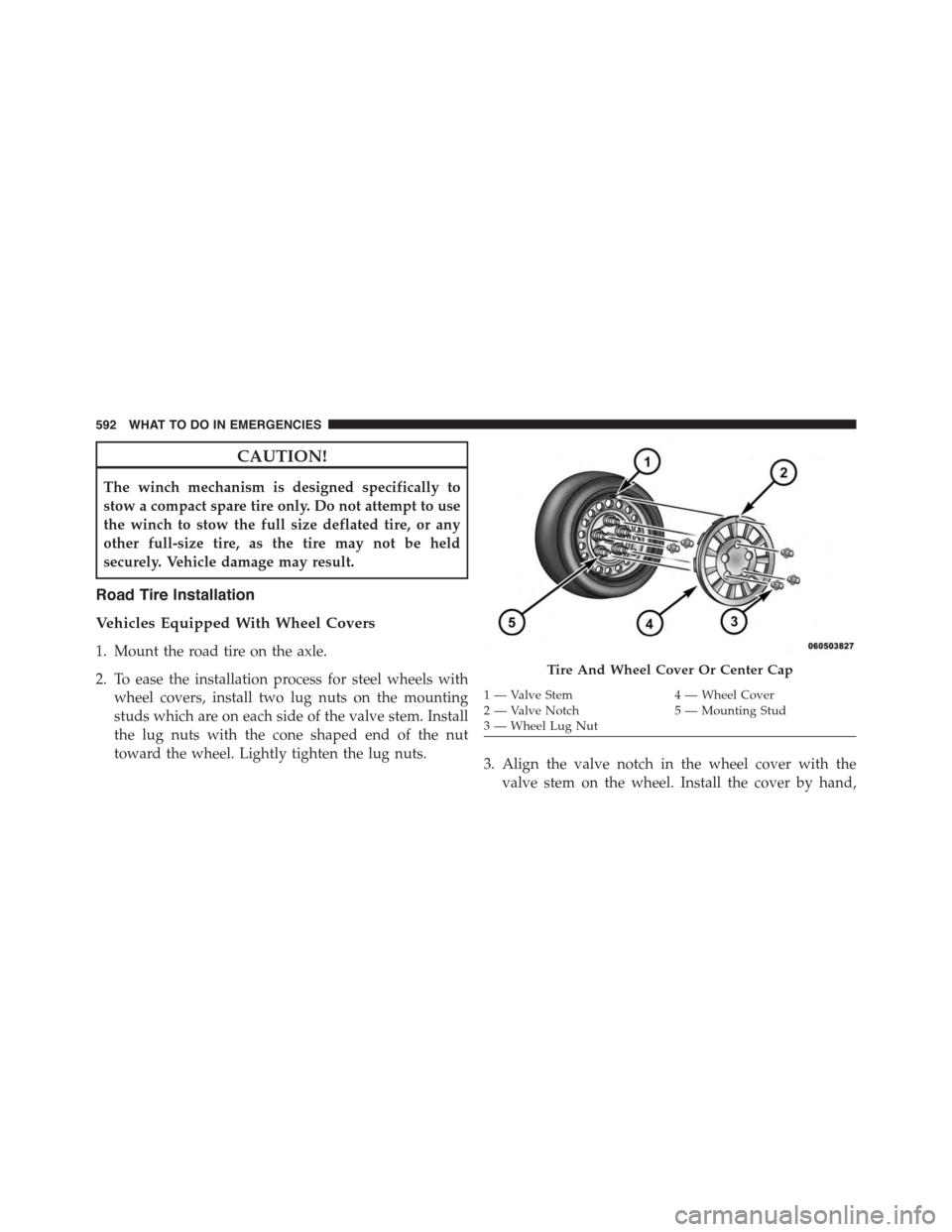
Tire And Wheel Cover Or Center Cap
1 — Valve Stem4 — Wheel Cover2—ValveNotch5—MountingStud3—WheelLugNut
592 WHAT TO DO IN EMERGENCIES
Page 604 of 703
If the key fob is unavailable or the vehicle’s battery is
discharged, refer to#Shift Lever Override#in this section
for instructions on shifting the transmission out of PARK
for towing.
CAUTION!
•Do not use sling type equipment when towing.
Vehicle damage may occur.
•When securing the vehicle to a flatbed truck, do not
attach to front or rear suspension components.
Damage to your vehicle may result from improper
towing.
•Do not push or tow this vehicle with another
vehicle as damage to the bumper fascia and trans-
mission may result.
The manufacturer recommends towing your vehicle with
all four wheels OFF the ground using a flatbed. If flatbed
equipment is not available, and the transmission is
operable, the vehicle may be flat towed (with all four
wheels on the ground) under the following conditions:
•The transmission must be in NEUTRAL.
•The towing distance must not exceed 15 miles (24 km).
•The towing speed must not exceed 25 mph (40 km/h).
If the transmission is not operable, or the vehicle must
be towed faster than 25 mph (40 km/h) or farther than 15
miles (24 km), it must be towed with the front wheels
OFF the ground (using a flatbed truck, or wheel lift
equipment with the front wheels raised).
602 WHAT TO DO IN EMERGENCIES
Page 623 of 703
A/C Air Filter
Refer to the “Maintenance Schedule” for the proper
maintenance intervals.
WARNING!
Do not remove the A/C air filter while the blower is
operating or personal injury may result.
The A/C air filter is located in the fresh air inlet behind
the glove box. Perform the following procedure to re-
place the filter:
1. Open the glove compartment and remove all contents.
2. Push in on the sides of the glove compartment and
lower the door.
3. Pivot the glove compartment downward.
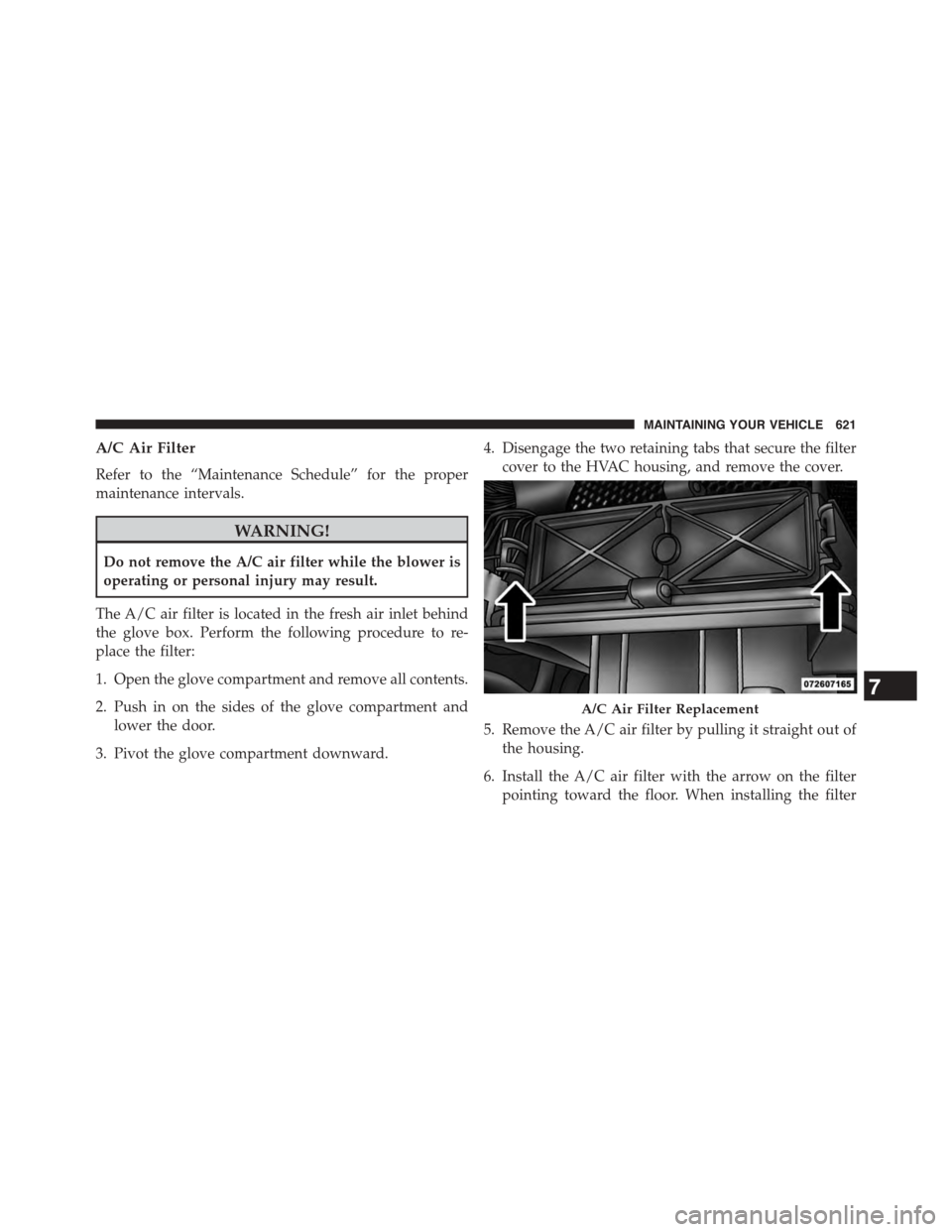
4. Disengage the two retaining tabs that secure the filter
cover to the HVAC housing, and remove the cover.
5. Remove the A/C air filter by pulling it straight out of
the housing.
6. Install the A/C air filter with the arrow on the filter
pointing toward the floor. When installing the filter
A/C Air Filter Replacement
7
MAINTAINING YOUR VEHICLE 621
Page 634 of 703
WARNING!
•Use only manufacturer’s recommended brake
fluid. Refer to “Fluids, Lubricants, and Genuine
Parts” in “Maintaining Your Vehicle” for further
information. Using the wrong type of brake fluid
can severely damage your brake system and/or
impair its performance. The proper type of brake
fluid for your vehicle is also identified on the
original factory installed hydraulic master cylinder
reservoir.
(Continued)
WARNING!(Continued)
•To avoid contamination from foreign matter or
moisture, use only new brake fluid or fluid that has
been in a tightly closed container. Keep the master
cylinder reservoir cap secured at all times. Brake
fluid in a open container absorbs moisture from the
air resulting in a lower boiling point. This may
cause it to boil unexpectedly during hard or pro-
longed braking, resulting in sudden brake failure.
This could result in a collision.
•Overfilling the brake fluid reservoir can result in
spilling brake fluid on hot engine parts, causing
the brake fluid to catch fire. Brake fluid can also
damage painted and vinyl surfaces, care should be
taken to avoid its contact with these surfaces.
(Continued)
632 MAINTAINING YOUR VEHICLE
Page 657 of 703
3. Twist the socket and remove from the lamp assembly.
4. Pull the bulb to remove it from the socket.
5. Replace the bulb, reinstall the socket, and reattach the
lamp assembly.
Center High-Mounted Stop Lamp (CHMSL)
The CHMSL uses LED lamps that are not serviceable
separately. The CHMSL must be replaced as an assembly.
See your authorized dealer.
License Lamp
The license plate lamp is located under the tailgate light
bar and above the license plate.
1. Using a small screwdriver, press inward the locking
tab on the outboard side of the lamp assembly and
pull down on the lamp assembly for removal.
2. Twist and remove the socket from the lamp assembly
and pull the bulb out to remove.
3. Push the bulb into the socket, twist the socket into the
lamp assembly and reinstall the lamp assembly into
place ensuring the locking tab is secure.
7
MAINTAINING YOUR VEHICLE 655
Page 682 of 703
About Your Brakes........................482
Adding Engine Coolant (Antifreeze)............626
Adding Fuel.............................540
Adding Washer Fluid......................623
Additives, Fuel...........................534
Air bag . . . . . . . . . . . . . . . . . . . . . . . . . . . . . . . . .80
Air Bag
Advance Front Air Bag....................81
Air Bag Components.....................80
Air bag Operation.......................83
Air Bag Warning Light....................92
Enhanced Accident Response................91
Event Data Recorder (EDR).................95
Front Air Bag . . . . . . . . . . . . . . . . . . . . . . . . . . .80
If A Deployment Occurs...................90
Knee Impact Bolsters.....................84
Maintaining Your Air Bag System............94
Side Air Bags...........................85
Air bag Deployment........................80
Air bag Light.............................92
Air bag Maintenance........................94
Air Cleaner, Engine (Engine Air Cleaner Filter) . . . .615
Air Conditioner Maintenance.................619
Air Conditioning..........................433
Air Conditioning Controls...................433
Air Conditioning Filter.....................452
Air Conditioning, Operating Tips..............451
Air Conditioning, Rear Zone.................438
Air Conditioning Refrigerant.................619
Air Conditioning System....................433
Air Conditioning System, Zone Control..........433
Air Pressure, Tires.........................508
Alarm Light.............................319
Alarm (Security Alarm)......................17
Alterations/Modifications, Vehicle...............7
Antenna, Satellite Radio.....................374
Antifreeze (Engine Coolant)..................625
Disposal..............................628
680 INDEX
Page 692 of 703
Headlights............................652
Headlights On Reminder..................224
High Beam Indicator.....................311
High Beam/Low Beam Select...............228
Illuminated Entry........................20
Interior..............................225
License..............................655
Lights On Reminder.....................224
Low Fuel.............................322
Malfunction Indicator (Check Engine).........316
Oil Pressure...........................323
Park................................652
Passing..............................229
Reading..............................253
Rear Servicing.........................654
Rear Tail Lamps........................654
Seat Belt Reminder......................321
Security Alarm.........................319
Service...............................650
Service Engine Soon (Malfunction Indicator) . . . .316
Side Marker...........................654
Tire Pressure Monitoring (TPMS)............315
Traction Control........................490
Turn Signal...........................125
Voltage..............................323
Warning (Instrument Cluster Description)......311
Loading Vehicle..........................285
Capacities............................544
Ti re s . . . . . . . . . . . . . . . . . . . . . . . . . . . . . . ..502
Load Leveling System......................294
Locks..................................34
Door.................................34
Lubrication, Body.........................622
Luggage Rack (Roof Rack)...................294
Lug Nuts...............................573
Maintenance Free Battery....................618
Maintenance Procedures....................612
690 INDEX