DODGE GRAND CARAVAN 2016 5.G Owners Manual
Manufacturer: DODGE, Model Year: 2016, Model line: GRAND CARAVAN, Model: DODGE GRAND CARAVAN 2016 5.GPages: 707, PDF Size: 5.24 MB
Page 311 of 707

INSTRUMENT CLUSTER — PREMIUM
4
UNDERSTANDING YOUR INSTRUMENT PANEL 309
Page 312 of 707
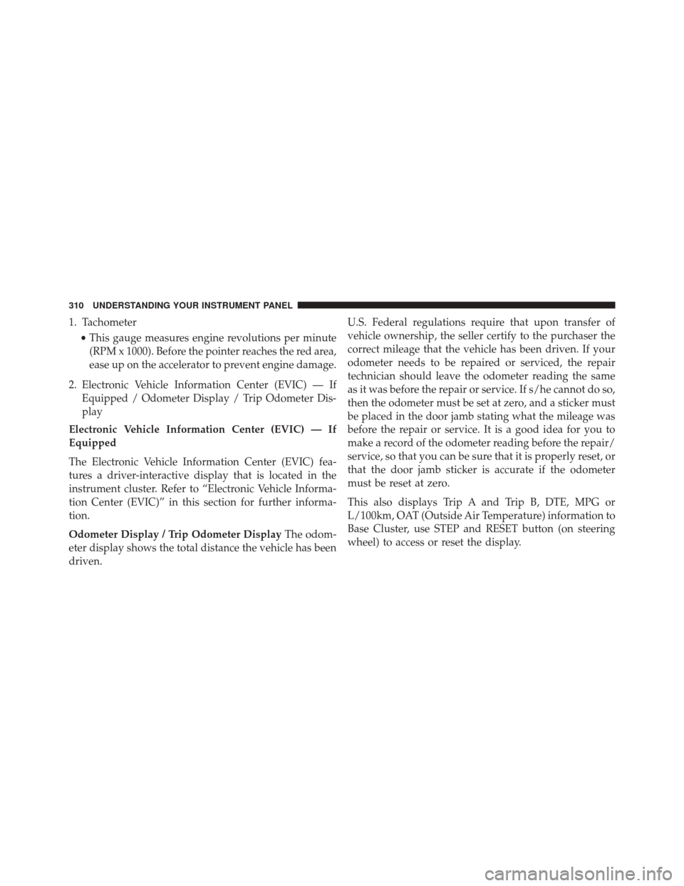
1. Tachometer•This gauge measures engine revolutions per minute
(RPM x 1000). Before the pointer reaches the red area,
ease up on the accelerator to prevent engine damage.
2. Electronic Vehicle Information Center (EVIC) — If Equipped / Odometer Display / Trip Odometer Dis-
play
Electronic Vehicle Information Center (EVIC) — If
Equipped
The Electronic Vehicle Information Center (EVIC) fea-
tures a driver-interactive display that is located in the
instrument cluster. Refer to “Electronic Vehicle Informa-
tion Center (EVIC)” in this section for further informa-
tion.
Odometer Display / Trip Odometer Display The odom-
eter display shows the total distance the vehicle has been
driven. U.S. Federal regulations require that upon transfer of
vehicle ownership, the seller certify to the purchaser the
correct mileage that the vehicle has been driven. If your
odometer needs to be repaired or serviced, the repair
technician should leave the odometer reading the same
as it was before the repair or service. If s/he cannot do so,
then the odometer must be set at zero, and a sticker must
be placed in the door jamb stating what the mileage was
before the repair or service. It is a good idea for you to
make a record of the odometer reading before the repair/
service, so that you can be sure that it is properly reset, or
that the door jamb sticker is accurate if the odometer
must be reset at zero.
This also displays Trip A and Trip B, DTE, MPG or
L/100km, OAT (Outside Air Temperature) information to
Base Cluster, use STEP and RESET button (on steering
wheel) to access or reset the display.
310 UNDERSTANDING YOUR INSTRUMENT PANEL
Page 313 of 707
Message Display Area
When the appropriate conditions exist, the following
odometer messages will display:
door............................. Door Ajar
gATE .......................... Liftgate Ajar
LoW tirE ....................LowTirePr essure
gASCAP ...................... Fuel Cap Fault
noFUSE .......................... Fuse Fault
CHAngE OIL ..............Oil Change Required
LoCOOL .......................Low CoolantNOTE:
Some of the above warnings will be displayed in
the Electronic Vehicle Information Center Display Area
located in the instrument cluster.
Refer to ”Electronic Vehicle Information Center (EVIC) —
If Equipped” in this section for further information.
LoW tirE
When the appropriate condition exists, the odometer
display will toggle between LoW and tirE for three
cycles.
gASCAP
If the vehicle diagnostic system determines that the fuel
filler cap is loose, improperly installed, or damaged, a
“gASCAP” message will display in the odometer display
area. Tighten the fuel filler cap properly and push the
STEP button on the steering wheel to turn off the
message. If the problem continues, the message will
appear the next time the vehicle is started.
4
UNDERSTANDING YOUR INSTRUMENT PANEL 311
Page 314 of 707
noFUSE
If the vehicle diagnostic system determines that the
Ignition Off Draw (IOD) fuse is improperly installed, or
damaged, a “noFUSE” message will display in the odom-
eter display area. Refer to “Fuses” in “Maintaining Your
Vehicle” for further information on fuses and fuse loca-
tions.
CHAngE OIL
Your vehicle is equipped with an engine oil change
indicator system. The odometer display will toggle be-
tweenCHAngE andOilfor approximately 12 seconds,
after a single chime has sounded, to indicate the next
scheduled oil change interval. The engine oil change
indicator system is duty cycle-based, which means the
engine oil change interval may fluctuate dependent upon
your personal driving style. Unless reset, this message will continue to display each
time you turn the ignition switch to the ON/RUN
position. To reset the oil change indicator system (after
performing the scheduled maintenance), perform the
following steps.
1. Turn the ignition switch to the ON/RUN position (do
not start the engine).
2. Fully push the accelerator pedal, slowly, three times
within 10 seconds.
3. Turn the ignition switch to the OFF position.
NOTE:
If the indicator message illuminates when you
start the engine, the oil change indicator system did not
reset. If necessary, repeat these steps.
3. Speedometer
•Indicates vehicle speed.
4. Fuel Gauge
312 UNDERSTANDING YOUR INSTRUMENT PANEL
Page 315 of 707
•The pointer shows the level of fuel in the fuel tank
when the ignition switch is in the ON/RUN position
The fuel pump symbol points to the side of the
vehicle where the fuel door is located.
5. Temperature Gauge
• The temperature gauge shows engine coolant tem-
perature. Any reading within the normal range indi-
cates that the engine cooling system is operating
satisfactorily.
• The gauge pointer will likely indicate a higher tem-
perature when driving in hot weather or up moun-
tain grades. It should not be allowed to exceed the
upper limits of the normal operating range.CAUTION!
Driving with a hot engine cooling system could
damage your vehicle. If the temperature gauge reads
“H” pull over and stop the vehicle. Idle the vehicle
with the air conditioner turned off until the pointer
drops back into the normal range. If the pointer
remains on the “H” and you hear continuous chimes,
turn the engine off immediately and call an autho-
rized dealer for service.
4
UNDERSTANDING YOUR INSTRUMENT PANEL 313
Page 316 of 707
WARNING!
A hot engine cooling system is dangerous. You or
others could be badly burned by steam or boiling
coolant. You may want to call an authorized dealer
for service if your vehicle overheats. If you decide to
look under the hood yourself, see “Maintaining Your
Vehicle”. Follow the warnings under the Cooling
System Pressure Cap paragraph.
WARNING AND INDICATOR LIGHTS
IMPORTANT:The warning light switches on in the
instrument panel together with a dedicated message
and/or acoustic signal when applicable. These indica-
tions are indicative and precautionary and as such must
not be considered as exhaustive and/or alternative to the
information contained in the Owner Manual, which you
are advised to read carefully in all cases. Always refer to
the information in this chapter in the event of a failure
indication.
314 UNDERSTANDING YOUR INSTRUMENT PANEL
Page 317 of 707
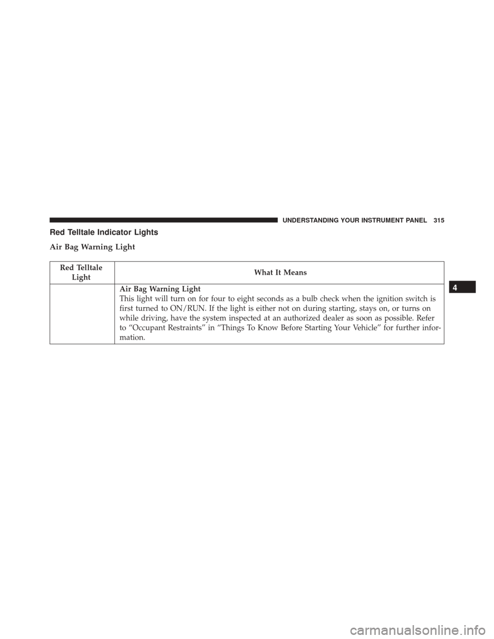
Red Telltale Indicator Lights
Air Bag Warning Light
Red TelltaleLight What It Means
Air Bag Warning Light
This light will turn on for four to eight seconds as a bulb check when the ignition switch is
first turned to ON/RUN. If the light is either not on during starting, stays on, or turns on
while driving, have the system inspected at an authorized dealer as soon as possible. Refer
to “Occupant Restraints” in “Things To Know Before Starting Your Vehicle” for further infor-
mation.4
UNDERSTANDING YOUR INSTRUMENT PANEL 315
Page 318 of 707
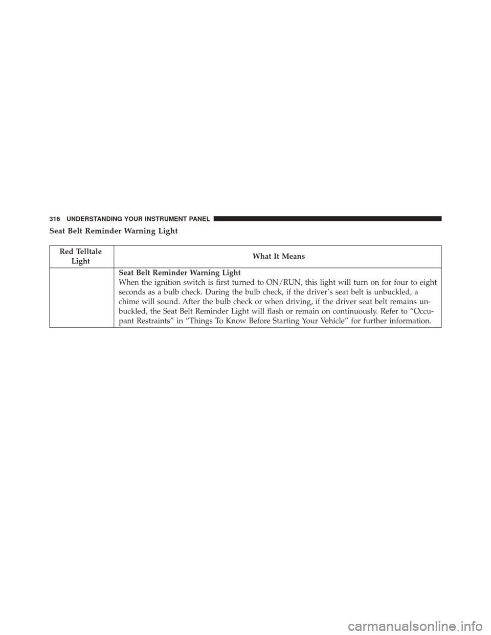
Seat Belt Reminder Warning Light
Red TelltaleLight What It Means
Seat Belt Reminder Warning Light
When the ignition switch is first turned to ON/RUN, this light will turn on for four to eight
seconds as a bulb check. During the bulb check, if the driver’s seat belt is unbuckled, a
chime will sound. After the bulb check or when driving, if the driver seat belt remains un-
buckled, the Seat Belt Reminder Light will flash or remain on continuously. Refer to “Occu-
pant Restraints” in “Things To Know Before Starting Your Vehicle” for further information.
316 UNDERSTANDING YOUR INSTRUMENT PANEL
Page 319 of 707
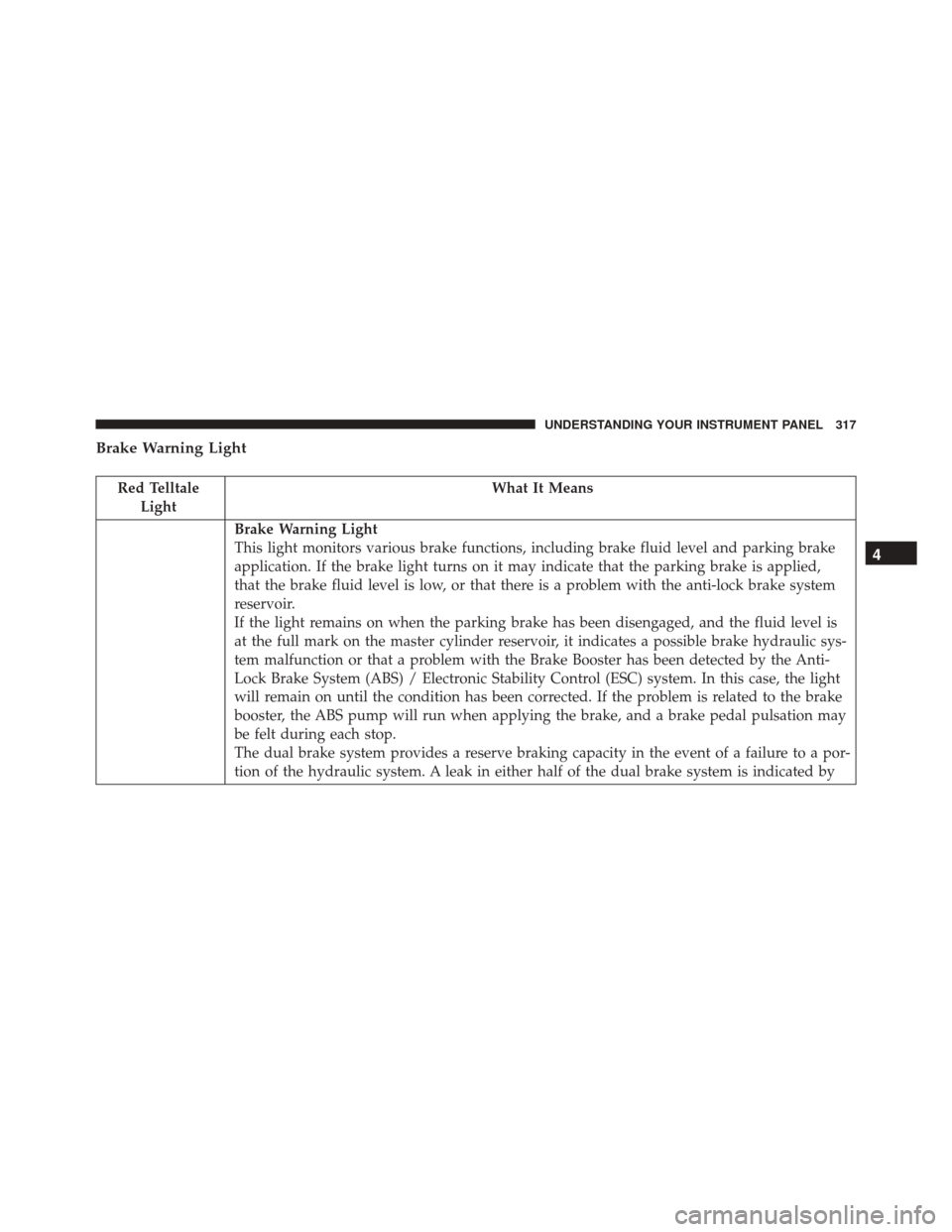
Brake Warning Light
Red TelltaleLight What It Means
Brake Warning Light
This light monitors various brake functions, including brake fluid level and parking brake
application. If the brake light turns on it may indicate that the parking brake is applied,
that the brake fluid level is low, or that there is a problem with the anti-lock brake system
reservoir.
If the light remains on when the parking brake has been disengaged, and the fluid level is
at the full mark on the master cylinder reservoir, it indicates a possible brake hydraulic sys-
tem malfunction or that a problem with the Brake Booster has been detected by the Anti-
Lock Brake System (ABS) / Electronic Stability Control (ESC) system. In this case, the light
will remain on until the condition has been corrected. If the problem is related to the brake
booster, the ABS pump will run when applying the brake, and a brake pedal pulsation may
be felt during each stop.
The dual brake system provides a reserve braking capacity in the event of a failure to a por-
tion of the hydraulic system. A leak in either half of the dual brake system is indicated by
4
UNDERSTANDING YOUR INSTRUMENT PANEL 317
Page 320 of 707
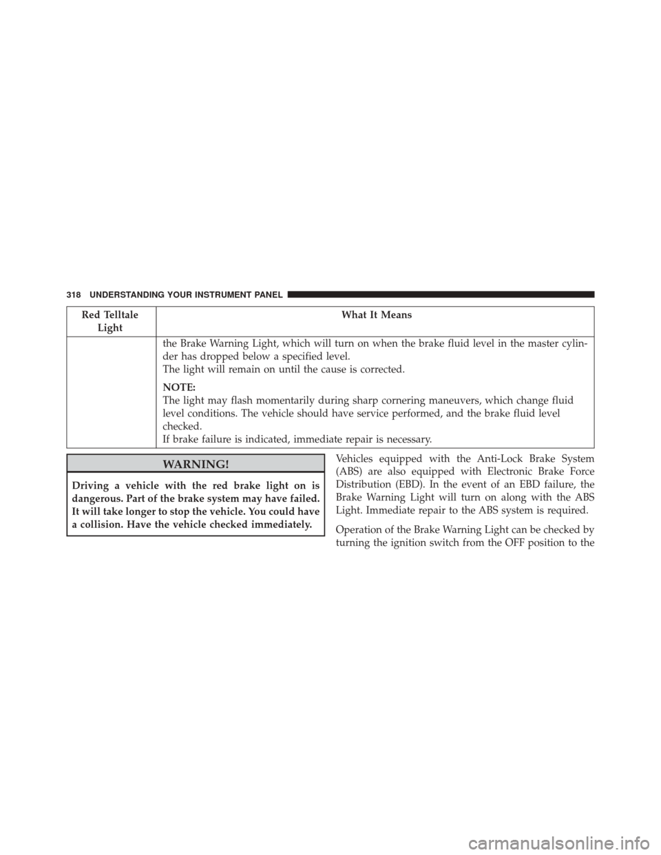
Red TelltaleLight What It Means
the Brake Warning Light, which will turn on when the brake fluid level in the master cylin-
der has dropped below a specified level.
The light will remain on until the cause is corrected.
NOTE:
The light may flash momentarily during sharp cornering maneuvers, which change fluid
level conditions. The vehicle should have service performed, and the brake fluid level
checked.
If brake failure is indicated, immediate repair is necessary.
WARNING!
Driving a vehicle with the red brake light on is
dangerous. Part of the brake system may have failed.
It will take longer to stop the vehicle. You could have
a collision. Have the vehicle checked immediately. Vehicles equipped with the Anti-Lock Brake System
(ABS) are also equipped with Electronic Brake Force
Distribution (EBD). In the event of an EBD failure, the
Brake Warning Light will turn on along with the ABS
Light. Immediate repair to the ABS system is required.
Operation of the Brake Warning Light can be checked by
turning the ignition switch from the OFF position to the
318 UNDERSTANDING YOUR INSTRUMENT PANEL