maintenance DODGE GRAND CARAVAN 2020 Owners Manual
[x] Cancel search | Manufacturer: DODGE, Model Year: 2020, Model line: GRAND CARAVAN, Model: DODGE GRAND CARAVAN 2020Pages: 380, PDF Size: 14.92 MB
Page 3 of 380
TABLE OF CONTENTS
1
2
3
4
5
6
7
8
9
10
11
1 INTRODUCTION .............................................................................................................................. 7
2 GETTING TO KNOW YOUR VEHICLE ................................................................................... 9
3 GETTING TO KNOW YOUR INSTRUMENT PANEL ........................................................82
4 SAFETY .........................................................................................................................................103 5 STARTING AND OPERATING ............................................................................................... 162
6 IN CASE OF EMERGENCY .....................................................................................................194 7 SERVICING AND MAINTENANCE ...................................................................................... 226
8 TECHNICAL SPECIFICATIONS ............................................................................................ 266
9 MULTIMEDIA .............................................................................................................................. 275
10 CUSTOMER ASSISTANCE .....................................................................................................364
11 INDEX ............................................................................................................................................. 368
20_RT_OM_EN_USC_t.book Page 1
Page 5 of 380

3
WINDOWS ............................................................59 Power Vent Windows — If Equipped .......... 59
Power Windows ............................................ 59
HOOD......................................................................61
Opening The Hood ....................................... 61
Closing The Hood ......................................... 61
LIFTGATE ................................................................62
Opening ........................................................ 62
Closing .......................................................... 62
Power Liftgate — If Equipped ...................... 62
Cargo Area Features ................................... 63
LOAD LEVELING SYSTEM — IF EQUIPPED .........63
GARAGE DOOR OPENER — IF EQUIPPED ..........63
Before You Begin Programming
HomeLink® .................................................. 64 Programming A Rolling Code ...................... 64
Programming A Non-Rolling Code............... 65
Canadian/Gate Operator Programming ..... 66
Using HomeLink® ........................................ 67
Security......................................................... 67
Troubleshooting Tips ................................... 67
General Information .................................... 68
INTERNAL EQUIPMENT ........................................68
Storage ......................................................... 68
Cupholders .................................................. 73
Sun Screens — If Equipped ......................... 75
Electrical Power Outlets — If Equipped....... 75
Power Inverter — If Equipped ...................... 77
Smoker's Package Kit — If Equipped ......... 78
Sunglass Storage Bin — If Equipped........... 78 ROOF LUGGAGE RACK — IF EQUIPPED ............. 79
Deploying The Crossbars............................. 79
Stowing The Crossbars................................ 80
GETTING TO KNOW YOUR INSTRUMENT PANEL
INSTRUMENT CLUSTER ...................................... 82 Instrument Cluster Descriptions ................ 84
INSTRUMENT CLUSTER DISPLAY ..................... 85
Instrument Cluster Display Location And
Controls ....................................................... 85 Oil Life Reset ................................................ 87
Instrument Cluster Display Menu Items .... 87
TRIP COMPUTER ................................................. 93
WARNING LIGHTS AND MESSAGES .................. 94 Red Warning Lights ..................................... 94
Yellow Warning Lights ................................. 97
White Indicator Lights ............................... 100Green Indicator Lights ............................... 100Blue Indicator Lights.................................. 100
ONBOARD DIAGNOSTIC SYSTEM — OBD II..... 101
Onboard Diagnostic System (OBD II)
Cybersecurity ............................................. 101
EMISSIONS INSPECTION AND
MAINTENANCE PROGRAMS .............................102
SAFETY
SAFETY FEATURES .............................................103
Anti-Lock Brake System (ABS) ................. 103
Electronic Brake Control (EBC) System ... 104 AUXILIARY DRIVING SYSTEMS ........................ 110
Blind Spot Monitoring (BSM)
— If Equipped ............................................. 110 Tire Pressure Monitoring System
(TPMS) ........................................................ 115
OCCUPANT RESTRAINT SYSTEMS ................. 119
Occupant Restraint Systems Features .... 119
Important Safety Precautions ................... 119
Seat Belt Systems .................................... 120Supplemental Restraint Systems (SRS)... 131
Child Restraints ......................................... 141Transporting Pets ..................................... 159
SAFETY TIPS ...................................................... 159
Transporting Passengers .......................... 159
Exhaust Gas ............................................... 159
Safety Checks You Should Make
Inside The Vehicle .................................... 160 Periodic Safety Checks You Should
Make Outside The Vehicle ........................ 161
STARTING AND OPERATING
STARTING THE ENGINE .................................... 162
Normal Starting ......................................... 162Cold Weather Operation
(Below –22°F Or −30°C) ......................... 163 After Starting — Warming Up The
Engine ........................................................ 163 If Engine Fails To Start ............................. 163
ENGINE BLOCK HEATER — IF EQUIPPED ........ 163
20_RT_OM_EN_USC_t.book Page 3
Page 7 of 380

5
SERVICING AND MAINTENANCE
SCHEDULED SERVICING .................................. 226Maintenance Plan......................................227
ENGINE COMPARTMENT .................................. 231
Engine Compartment — 3.6L ....................231
Checking Oil Level......................................232
Adding Washer Fluid .................................232
Maintenance-Free Battery .......................232
Pressure Washing ......................................233
DEALER SERVICE .............................................. 233
Engine Oil .................................................. 233Engine Oil Filter ..........................................234Engine Air Cleaner Filter ...........................235
Air Conditioner Maintenance ...................235Accessory Drive Belt Inspection................236Body Lubrication ........................................237
Windshield Wiper Blades ..........................238
Exhaust System ........................................238
Cooling System ..........................................239Brake System ............................................242
Automatic Transmission ............................243
RAISING THE VEHICLE ...................................... 244
TIRES ................................................................... 245
Tire Safety Information .............................245Tires — General Information .....................252Tire Types ...................................................256
Spare Tires — If Equipped .........................257
Wheel And Wheel Trim Care ....................259
Tire Chains and Traction Devices ............260
Tire Rotation Recommendations .............261 DEPARTMENT OF TRANSPORTATION
UNIFORM TIRE QUALITY GRADES .................. 261
Treadwear .................................................. 261
Traction Grades ......................................... 261
Temperature Grades ................................. 262
VEHICLE STORAGE .............................................262
BODYWORK ........................................................ 262
Protection From Atmospheric Agents....... 262
Body And Underbody Maintenance .......... 263Preserving The Bodywork .......................... 263
INTERIORS ......................................................... 264
Seats And Fabric Parts .............................. 264
Plastic And Coated Parts ........................... 264
Glass Surfaces .......................................... 265Cleaning The Instrument Panel
Cupholders ................................................. 265
TECHNICAL SPECIFICATIONS
IDENTIFICATION DATA .......................................266
Vehicle Identification Number .................. 266
BRAKE SYSTEM .................................................. 266
WHEEL AND TIRE TORQUE
SPECIFICATIONS ................................................ 266
Torque Specifications ................................ 266
FUEL REQUIREMENTS ......................................267
3.6L Engine ................................................ 267
Reformulated Gasoline ............................ 268
Materials Added To Fuel ........................... 268
Gasoline/Oxygenate Blends ..................... 268 Do Not Use E-85 In Non-Flex Fuel
Vehicles ...................................................... 269 CNG And LP Fuel System
Modifications ............................................. 269 MMT In Gasoline........................................ 269
Fuel System Cautions................................ 270
Carbon Monoxide Warnings...................... 270
FLUID CAPACITIES ............................................ 271
FLUIDS AND LUBRICANTS ................................ 272
Engine ........................................................ 272
Chassis ....................................................... 274
MULTIMEDIA
CYBERSECURITY ............................................... 275
SAFETY AND GENERAL INFORMATION .......... 276Safety Guidelines....................................... 276
RADIO 430/430 NAV........................................ 277
General Handling....................................... 277
Getting Started .......................................... 279
Radio Mode ................................................ 281
Media Mode ............................................... 286
Remote Devices......................................... 299Uconnect Phone— If Equipped ................. 304
Navigation — If Equipped .......................... 317
STEERING WHEEL AUDIO CONTROLS — IF
EQUIPPED .......................................................... 340
Radio Operation......................................... 340CD Player.................................................... 340
20_RT_OM_EN_USC_t.book Page 5
Page 9 of 380
7
INTRODUCTION
Dear Customer,
Congratulations on selecting your new vehicle. Be assured that it represents precision workmanship, distinctive styling, and high quality. This Owner’s
Manual has been prepared with the assistance of service and engineering specialists to acquaint you with the operation and maintenance of your
vehicle. It is supplemented by Warranty Information and customer oriented documents. Within this information, you will find a description of the services
that FCA US LLC offers to its customers, the vehicle's warranty coverage, and the details of the terms and conditions for maintaining its validity. Please
take the time to read all of these publications carefully before driving your vehicle for the first time. Following the instructions, recommendations, tips,
and important warnings in this manual will help assure safe and enjoyable operation of your vehicle. Be sure you are familiar with all vehicle controls,
particularly those used for braking, steering, transmission, and transfer case shifting (if equipped). Learn how your vehicle handles on different road
surfaces. Your driving skills will improve with experience.
This Owner’s Manual describes all versions of this vehicle. Options and equipment dedicated to specific markets or versions are not expressly indicated
in the text. Therefore, you should only consider the information which is related to the trim level, engine, and version that you have purchased. Any
content introduced throughout the Owner’s Information, that may or may not be applicable to your vehicle, will be identified with the wording “If
Equipped”. All data contained in this publication are intended to help you use your vehicle in the best possible way. FCA US LLC aims at a constant
improvement of the vehicles produced. For this reason, it reserves the right to make changes to the model described for technical and/or commercial
reasons. For further information, contact an authorized dealer.
When it comes to service, remember that authorized dealers know your vehicle best, have factory-trained technicians and genuine MOPAR® parts, and
care about your satisfaction.1
20_RT_OM_EN_USC_t.book Page 7
Page 87 of 380
GETTING TO KNOW YOUR INSTRUMENT PANEL85
NOTE:
The hard telltales will illuminate for a bulb check
when the ignition is first cycled.
INSTRUMENT CLUSTER DISPLAY
Your vehicle is equipped with an instrument
cluster display, which offers useful information
to the driver. With the ignition in the OFF
position (and the key removed, for vehicles with
mechanical key), opening/closing of a door will
activate the display for viewing, and display the
total miles or kilometers in the odometer. Your
instrument cluster display is designed to display
important information about your vehicle’s
systems and features. Using a driver interactive
display located on the instrument panel, your
instrument cluster display can show you how
systems are working and give you warnings
when they are not. The steering wheel mounted
controls allow you to scroll through and enter
the main menus and submenus. You can
access the specific information you want and
make selections and adjustments.
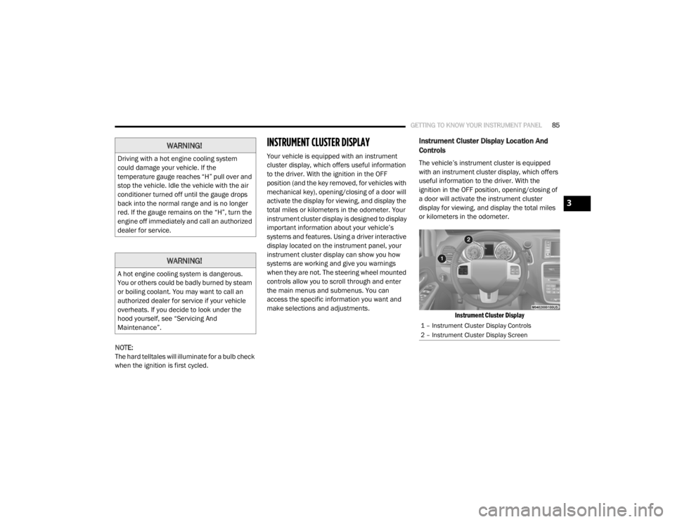
Instrument Cluster Display Location And
Controls
The vehicle’s instrument cluster is equipped
with an instrument cluster display, which offers
useful information to the driver. With the
ignition in the OFF position, opening/closing of
a door will activate the instrument cluster
display for viewing, and display the total miles
or kilometers in the odometer.
Instrument Cluster Display
WARNING!
Driving with a hot engine cooling system
could damage your vehicle. If the
temperature gauge reaches “H” pull over and
stop the vehicle. Idle the vehicle with the air
conditioner turned off until the gauge drops
back into the normal range and is no longer
red. If the gauge remains on the “H”, turn the
engine off immediately and call an authorized
dealer for service.
WARNING!
A hot engine cooling system is dangerous.
You or others could be badly burned by steam
or boiling coolant. You may want to call an
authorized dealer for service if your vehicle
overheats. If you decide to look under the
hood yourself, see “Servicing And
Maintenance”.
1 – Instrument Cluster Display Controls
2 – Instrument Cluster Display Screen
3
20_RT_OM_EN_USC_t.book Page 85
Page 89 of 380

GETTING TO KNOW YOUR INSTRUMENT PANEL87
Oil Life Reset
Your vehicle is equipped with an engine oil
change indicator system. The “Oil Change
Required” message will display for approxi-
mately 10 seconds after a single chime has
sounded, to indicate the next scheduled oil
change interval. The engine oil change indi-
cator system is duty cycle based, which
means the engine oil change interval may
fluctuate, dependent upon your personal
driving style.
Unless reset, this message will continue to
display each time the ignition is cycled to the
ON/RUN position.
To reset the oil change indicator after
performing the scheduled maintenance,
refer to the following procedure.
1. Turn the ignition to the ON/RUN position (do not start the engine).
2. Fully press the accelerator pedal, slowly, three times within 10 seconds.
3. Turn the ignition to the OFF/LOCK position. NOTE:
If the indicator message illuminates when you
start the vehicle, the oil change indicator
system did not reset. If necessary, repeat this
procedure.
Instrument Cluster Display Menu Items
NOTE:
The instrument cluster display menu items
display in the center of the instrument cluster.
Menu items may vary depending on your vehicle
features.
Fuel Economy
Push and release the
up or down arrow button
until “Fuel Economy” displays highlighted in the
instrument cluster display and push the right
arrow button. The following Fuel Economy
functions display in the instrument cluster
display:
Average Fuel Economy
(MPG, L/100 km or km/L)
Distance To Empty (mi or km)
Current Fuel Economy (MPG, L/100 km or
km/L)
Vehicle Speed
Push and release the up or down arrow button
until “Vehicle Speed” displays highlighted in the
instrument cluster display and push the right
arrow button. Push and release the right arrow
button to display the current speed in mph or
km/h. Pushing the right arrow button a second
time will toggle the unit of measure between
mph or km/h.
NOTE:
Changing the unit of measure in the Vehicle
Speed menu will not change the unit of
measure in the instrument cluster display.
Trip Info
Push and release the up or down arrow button
until “Trip Info” is highlighted in the instrument
cluster display and push the right button. Push
and release the up or down arrow button to
highlight one of the following functions:
Trip A
Trip B
Elapsed Time
Trip Reset
3
20_RT_OM_EN_USC_t.book Page 87
Page 99 of 380
GETTING TO KNOW YOUR INSTRUMENT PANEL97
Vehicle Security Warning Light — If Equipped
This light will flash at a fast rate for
approximately 15 seconds when the
vehicle security alarm is arming, and
then will flash slowly until the vehicle
is disarmed.
Yellow Warning Lights
Anti-Lock Brake (ABS) Warning Light
This warning light monitors the
Anti-Lock Brake System (ABS). The
light will turn on when the ignition is
placed in the ON/RUN or ACC/ON/
RUN position and may stay on for as long as four
seconds.
If the ABS light remains on or turns on while
driving, then the Anti-Lock portion of the brake
system is not functioning and service is
required as soon as possible. However, the
conventional brake system will continue to
operate normally, assuming the Brake Warning
Light is not also on.
If the ABS light does not turn on when the
ignition is placed in the ON/RUN or ACC/ON/
RUN position, have the brake system inspected
by an authorized dealer.
Electronic Stability Control (ESC) Active
Warning Light — If Equipped
This warning light will indicate when
the Electronic Stability Control system
is Active. The “ESC Indicator Light” in
the instrument cluster will come on
when the ignition is placed in the ON/RUN or
ACC/ON/RUN position, and when ESC is
activated. It should go out with the engine
running. If the “ESC Indicator Light” comes on
continuously with the engine running, a
malfunction has been detected in the ESC
system. If this warning light remains on after
several ignition cycles, and the vehicle has been
driven several miles (kilometers) at speeds
greater than 30 mph (48 km/h), see an
authorized dealer as soon as possible to have
the problem diagnosed and corrected.
The “ESC OFF Indicator Light” and the “ESC
Indicator Light” come on momentarily each
time the ignition is placed in the ON/RUN or
ACC/ON/RUN position.
The ESC system will make buzzing or clicking
sounds when it is active. This is normal; the
sounds will stop when ESC becomes inactive.
This light will come on when the vehicle is in
an ESC event.
Electronic Stability Control (ESC) OFF
Warning Light — If Equipped
This warning light indicates the
Electronic Stability Control (ESC) is
off.
Each time the ignition is turned to ON/RUN or
ACC/ON/RUN, the ESC system will be on, even
if it was turned off previously.
Low Fuel Warning Light
When the fuel level reaches approxi -
mately 1.85 gal (7 L) this warning light
will turn on, and remain on until fuel is
added.
A single warning chime will sound with Low Fuel
Warning.
Low Washer Fluid Warning Light — If
Equipped
This warning light will illuminate when
the windshield washer fluid is low.
Refer to “Engine Compartment” in “Servicing
And Maintenance” for further information.
3
20_RT_OM_EN_USC_t.book Page 97
Page 101 of 380

GETTING TO KNOW YOUR INSTRUMENT PANEL99
Each tire, including the spare (if provided),
should be checked monthly when cold and
inflated to the inflation pressure recommended
by the vehicle manufacturer on the vehicle
placard or tire inflation pressure label. If your
vehicle has tires of a different size than the size
indicated on the vehicle placard or tire inflation
pressure label, you should determine the
proper tire inflation pressure for those tires.
As an added safety feature, your vehicle has
been equipped with a Tire Pressure Monitoring
System (TPMS) that illuminates a low tire
pressure telltale when one or more of your tires
is significantly under-inflated. Accordingly, when
the low tire pressure telltale illuminates, you
should stop and check your tires as soon as
possible, and inflate them to the proper
pressure. Driving on a significantly
under-inflated tire causes the tire to overheat
and can lead to tire failure. Under-inflation also
reduces fuel efficiency and tire tread life, and
may affect the vehicle’s handling and stopping
ability. Please note that the TPMS is not a substitute for
proper tire maintenance, and it is the driver’s
responsibility to maintain correct tire pressure,
even if under-inflation has not reached the level
to trigger illumination of the TPMS low tire
pressure telltale.
Your vehicle has also been equipped with a
TPMS malfunction indicator to indicate when
the system is not operating properly. The TPMS
malfunction indicator is combined with the low
tire pressure telltale. When the system detects
a malfunction, the telltale will flash for approxi
-
mately one minute and then remain contin -
uously illuminated. This sequence will continue
upon subsequent vehicle start-ups as long as
the malfunction exists. When the malfunction
indicator is illuminated, the system may not be
able to detect or signal low tire pressure as
intended. TPMS malfunctions may occur for a
variety of reasons, including the installation of
replacement or alternate tires or wheels on the
vehicle that prevent the TPMS from functioning
properly. Always check the TPMS malfunction
telltale after replacing one or more tires or
wheels on your vehicle to ensure that the
replacement or alternate tires and wheels allow
the TPMS to continue to function properly.CAUTION!
The TPMS has been optimized for the original
equipment tires and wheels. TPMS pressures
and warning have been established for the
tire size equipped on your vehicle.
Undesirable system operation or sensor
damage may result when using replacement
equipment that is not of the same size, type,
and/or style. Aftermarket wheels can cause
sensor damage. Using aftermarket tire
sealants may cause the Tire Pressure
Monitoring System (TPMS) sensor to become
inoperable. After using an aftermarket tire
sealant it is recommended that you take your
vehicle to an authorized dealer to have your
sensor function checked.
3
20_RT_OM_EN_USC_t.book Page 99
Page 104 of 380

102GETTING TO KNOW YOUR INSTRUMENT PANEL
EMISSIONS INSPECTION AND
MAINTENANCE PROGRAMS
In some localities, it may be a legal requirement
to pass an inspection of your vehicle's
emissions control system. Failure to pass could
prevent vehicle registration.
For states that require an Inspection
and Maintenance (I/M), this check
verifies the “Malfunction Indicator
Light (MIL)” is functioning and is not
on when the engine is running, and that the
OBD II system is ready for testing.
Normally, the OBD II system will be ready. The
OBD II system may not be ready if your vehicle
was recently serviced, recently had a depleted
battery or a battery replacement. If the OBD II
system should be determined not ready for the
I/M test, your vehicle may fail the test.
Your vehicle has a simple ignition actuated test,
which you can use prior to going to the test
station. To check if your vehicle's OBD II system
is ready, you must do the following:
1. Cycle the ignition switch to the ON position,
but do not crank or start the engine.
NOTE:
If you crank or start the engine, you will have to
start this test over.
2. As soon as you cycle the ignition switch to the ON position, you will see the
“Malfunction Indicator Light (MIL)” symbol
come on as part of a normal bulb check.
3. Approximately 15 seconds later, one of two things will happen:
The MIL will flash for about 10 seconds
and then return to being fully illuminated
until you turn OFF the ignition or start the
engine. This means that your vehicle's
OBD II system is not ready and you should
not proceed to the I/M station.
The MIL will not flash at all and will remain
fully illuminated until you place the ignition
in the off position or start the engine. This
means that your vehicle's OBD II system is
ready and you can proceed to the I/M
station. If your OBD II system is not ready,
you should
see an authorized dealer or repair facility. If your
vehicle was recently serviced or had a battery
failure or replacement, you may need to do
nothing more than drive your vehicle as you
normally would in order for your OBD II system
to update. A recheck with the above test routine
may then indicate that the system is now ready.
Regardless of whether your vehicle's OBD II
system is ready or not, if the MIL is illuminated
during normal vehicle operation you should
have your vehicle serviced before going to the
I/M station. The I/M station can fail your vehicle
because the MIL is on with the engine running.
20_RT_OM_EN_USC_t.book Page 102
Page 108 of 380
106SAFETY
(Continued)
ESC Operating Modes
NOTE:
Depending upon model and mode of operation,
the ESC system may have multiple operating
modes.
ESC On
This is the normal operating mode for the ESC.
Whenever the vehicle is started, the ESC system
will be in this mode. This mode should be used
for most driving conditions. Alternate ESC
modes should only be used for specific reasons
as noted in the following paragraphs.
Partial Off
The “Partial Off” mode is intended for times
when a more spirited driving experience is
desired. This mode may modify TCS and ESC
thresholds for activation, which allows for more
wheel spin than normally allowed. This mode
may be useful if the vehicle becomes stuck.
WARNING!
Electronic Stability Control (ESC) cannot
prevent the natural laws of physics from
acting on the vehicle, nor can it increase
the traction afforded by prevailing road
conditions. ESC cannot prevent accidents,
including those resulting from excessive
speed in turns, driving on very slippery
surfaces, or hydroplaning. ESC also cannot
prevent accidents resulting from loss of
vehicle control due to inappropriate driver
input for the conditions. Only a safe, atten -
tive, and skillful driver can prevent acci -
dents. The capabilities of an ESC equipped
vehicle must never be exploited in a reck -
less or dangerous manner which could
jeopardize the user’s safety or the safety of
others.Vehicle modifications, or failure to properly
maintain your vehicle, may change the
handling characteristics of your vehicle,
and may negatively affect the performance
of the ESC system. Changes to the steering
system, suspension, braking system, tire
type and size or wheel size may adversely
affect ESC performance. Improperly
inflated and unevenly worn tires may also
degrade ESC performance. Any vehicle
modification or poor vehicle maintenance
that reduces the effectiveness of the ESC
system can increase the risk of loss of
vehicle control, vehicle rollover, personal
injury and death.
WARNING! (Continued)
20_RT_OM_EN_USC_t.book Page 106