Lug nut DODGE HORNET 2023 Owners Manual
[x] Cancel search | Manufacturer: DODGE, Model Year: 2023, Model line: HORNET, Model: DODGE HORNET 2023Pages: 288, PDF Size: 14.2 MB
Page 52 of 288
50GETTING TO KNOW YOUR VEHICLE
Winter Operation
To ensure the best possible heater and defroster
performance, make sure the engine cooling system is
functioning properly and the proper amount, type, and
concentration of coolant is used. Use of the Air
Recirculation mode during Winter months is not
recommended, because it may cause window fogging.
Vacation/Storage
For information on maintaining the Climate Control system
when the vehicle is being stored for an extended period of
time, see
Úpage 261.
Window Fogging
Vehicle windows tend to fog on the inside in mild, rainy,
and/or humid weather. To clear the windows, select
Defrost or Mix mode and increase the front blower speed.
Do not use the Recirculation mode without A/C for long
periods, as fogging may occur.
Outside Air Intake
Make sure the air intake, located directly in front of the
windshield, is free of obstructions, such as leaves. Leaves
collected in the air intake may reduce airflow, and if they
enter the air distribution box, they could plug the water
drains. In Winter months, make sure the air intake is clear
of ice, slush, and snow.
Cabin Air Filter
The Climate Control system filters out dust and pollen
from the air. Contact an authorized dealer to service your
cabin air filter, and to have it replaced when needed.
Operating Tips ChartINTERIOR STORAGE AND EQUIPMENT
STORAGE
Glove Compartment
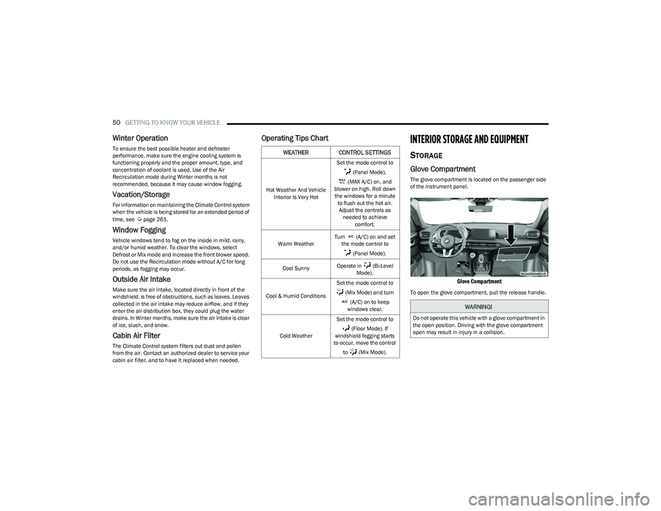
The glove compartment is located on the passenger side
of the instrument panel.
Glove Compartment
To open the glove compartment, pull the release handle.
WEATHER CONTROL SETTINGS
Hot Weather And Vehicle
Interior Is Very Hot Set the mode control to
(Panel Mode),
(MAX A/C) on, and
blower on high. Roll down the windows for a minute to flush out the hot air. Adjust the controls as needed to achieve comfort.
Warm Weather Turn (A/C) on and set
the mode control to
(Panel Mode).
Cool Sunny Operate in (Bi-Level
Mode).
Cool & Humid Conditions Set the mode control to
(Mix Mode) and turn (A/C) on to keep
windows clear.
Cold Weather Set the mode control to
(Floor Mode). If
windshield fogging starts
to occur, move the control
to (Mix Mode).
WARNING!
Do not operate this vehicle with a glove compartment in
the open position. Driving with the glove compartment
open may result in injury in a collision.
23_GG_OM_EN_USC_t.book Page 50
Page 203 of 288
SAFETY201
PERIODIC SAFETY CHECKS YOU SHOULD
M
AKE OUTSIDE THE VEHICLE
Tires
Examine tires for excessive tread wear and uneven wear
patterns. Check for stones, nails, glass, or other objects
lodged in the tread or sidewall. Inspect the tread for cuts
and cracks. Inspect sidewalls for cuts, cracks, and bulges.
Check the lug nut/bolt torque for tightness. Check the
tires (including spare) for proper cold inflation pressure.
Lights
Have someone observe the operation of brake lights and
exterior lights while you work the controls. Check turn
signal and high beam indicator lights on the instrument
panel.
Door Latches
Check for proper closing, latching, and locking.
Fluid Leaks
Check area under the vehicle after overnight parking for
fuel, coolant, oil, or other fluid leaks. Also, if gasoline
fumes are detected or if fuel or brake fluid leaks are
suspected, the cause should be located and corrected
immediately.
ALWAYS make sure objects cannot fall or slide into
the driver’s side floor area when the vehicle is
moving. Objects can become trapped under acceler -
ator, brake, or clutch pedals and could cause a loss
of vehicle control.
NEVER place any objects under the floor mat (e.g.,
towels, keys, etc.). These objects could change the
position of the floor mat and may cause interference
with the accelerator, brake, or clutch pedals.
If the vehicle carpet has been removed and
re-installed, always properly attach carpet to the floor
and check the floor mat fasteners are secure to the
vehicle carpet. Fully depress each pedal to check for
interference with the accelerator, brake, or clutch
pedals then re-install the floor mats.
It is recommended to only use mild soap and water
to clean your floor mats. After cleaning, always check
your floor mat has been properly installed and is
secured to your vehicle using the floor mat fasteners
by lightly pulling mat.
WARNING!
6
23_GG_OM_EN_USC_t.book Page 201
Page 215 of 288
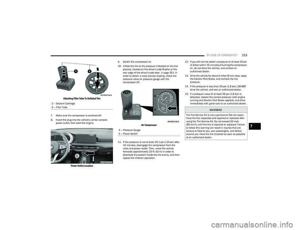
IN CASE OF EMERGENCY213
Attaching Filler Tube To Deflated Tire
7. Make sure the compressor is switched off.
8. Insert the plug into the vehicle’s center console
power outlet, then start the engine.
Power Outlet Location
9. Switch the compressor on.
10. Inflate the tire to the pressure indicated on the tire placard, located on the driver’s side B-pillar or the
rear edge of the driver’s side door
Úpage 251. In
order to obtain a more precise reading, check the
pressure value on pressure gauge with the
compressor off.
Air Compressor
11. If the pressure is not at least 26.1 psi (1.8 bar) after 15 minutes, disengage the compressor from the
valve and power outlet. Then, move the vehicle
forwards approximately 33 ft (10 m) in order to
distribute the sealant inside the tire evenly, and then
repeat the inflation operation. 12. If you still cannot obtain a pressure of at least 26 psi
(1.8 bar) within 15 minutes of turning the compressor
on, do not drive the vehicle, and contact an
authorized dealer.
13. Drive the vehicle for about 5 miles (8 km), stop, apply the Electric Park Brake, and recheck the tire
pressure.
14. If the pressure is less than 26 psi (1.8 bar), DO NOT
drive the vehicle, and see an authorized dealer.
15. If a pressure value of at least 26 psi (1.8 bar) is detected, restore the correct pressure (with engine
running and Electric Park Brake applied), and drive
immediately with great care to an authorized dealer.
2 — Sealant Cartridge
3 — Filler Tube
4 — Pressure Gauge
5 — Power Switch
WARNING!
The Tire Service Kit is not a permanent flat tire repair.
Have the tire inspected and repaired or replaced after
using the Tire Service Kit. Do not exceed 50 mph
(80 km/h) until the tire is repaired or replaced. Failure
to follow this warning can result in injuries that are
serious or fatal to you, your passengers, and others
around you. Have the tire checked as soon as possible
at an authorized dealer.
7
23_GG_OM_EN_USC_t.book Page 213
Page 218 of 288
216IN CASE OF EMERGENCY
JUMP STARTING PROCEDURE
Connecting The Jumper Cables
1. Connect the positive
(+) end of the jumper cable to
the positive (+)
post of the discharged vehicle.
2. Connect the opposite end of the positive (+) jumper
cable to the positive (+) post of the booster battery.
3. Connect the negative (-) end of the jumper cable to
the negative (-) post of the booster battery.
4. Connect the opposite end of the negative (-) jumper
cable to a good engine ground. A “ground” is an
exposed metallic/unpainted part of the engine, frame
or chassis, such as an accessory bracket or large bolt.
The ground must be away from the battery and the
fuel injection system.
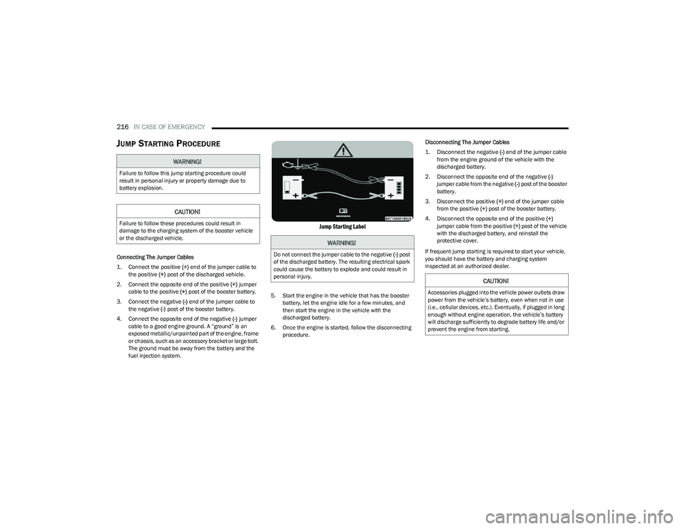
Jump Starting Label
5. Start the engine in the vehicle that has the booster battery, let the engine idle for a few minutes, and
then start the engine in the vehicle with the
discharged battery.
6. Once the engine is started, follow the disconnecting procedure. Disconnecting The Jumper Cables
1. Disconnect the negative
(-)
end of the jumper cable
from the engine ground of the vehicle with the
discharged battery.
2. Disconnect the opposite end of the negative (-)
jumper cable from the negative (-) post of the booster
battery.
3. Disconnect the positive (+) end of the jumper cable
from the positive (+) post of the booster battery.
4. Disconnect the opposite end of the positive (+)
jumper cable from the positive (+) post of the vehicle
with the discharged battery, and reinstall the
protective cover.
If frequent jump starting is required to start your vehicle,
you should have the battery and charging system
inspected at an authorized dealer.
WARNING!
Failure to follow this jump starting procedure could
result in personal injury or property damage due to
battery explosion.
CAUTION!
Failure to follow these procedures could result in
damage to the charging system of the booster vehicle
or the discharged vehicle.
WARNING!
Do not connect the jumper cable to the negative (-) post
of the discharged battery. The resulting electrical spark
could cause the battery to explode and could result in
personal injury.
CAUTION!
Accessories plugged into the vehicle power outlets draw
power from the vehicle’s battery, even when not in use
(i.e., cellular devices, etc.). Eventually, if plugged in long
enough without engine operation, the vehicle’s battery
will discharge sufficiently to degrade battery life and/or
prevent the engine from starting.
23_GG_OM_EN_USC_t.book Page 216
Page 267 of 288
265
TECHNICAL SPECIFICATIONS
VEHICLE IDENTIFICATION NUMBER (VIN)
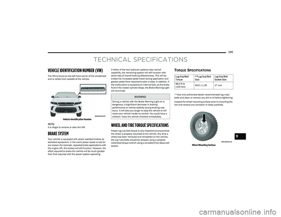
The VIN is found on the left front corner of the windshield
and is visible from outside of the vehicle.
Vehicle Identification Number
NOTE:
It is illegal to remove or alter the VIN.
BRAKE SYSTEM
Your vehicle is equipped with power assisted brakes as
standard equipment. In the event power assist is lost for
any reason (for example, repeated brake applications with
the engine off), the brakes will still function. However, the
effort required to brake the vehicle will be much greater
than that required with the power system operating. If either of the two hydraulic systems lose normal
capability, the remaining system will still function with
some loss of overall braking effectiveness. This will be
evident by increased pedal travel during application and
greater pedal force required to slow or stop. In addition, if
the malfunction is caused by an internal leak, as the brake
fluid in the master cylinder drops, the Brake Warning Light
will illuminate.
WHEEL AND TIRE TORQUE SPECIFICATIONS
Proper lug nut/bolt torque is very important to ensure that
the wheel is properly mounted to the vehicle. Any time a
wheel has been removed and reinstalled on the vehicle,
the lug nuts/bolts should be torqued using a properly
calibrated torque wrench using a six-sided (hex) deep wall
socket.
TORQUE SPECIFICATIONS
**Use only authorized dealer recommended lug nuts/
bolts and clean or remove any dirt or oil before tightening.
Inspect the wheel mounting surface prior to mounting the
tire and remove any corrosion or loose particles.
Wheel Mounting Surface
WARNING!
Driving a vehicle with the Brake Warning Light on is
dangerous. A significant decrease in braking
performance or vehicle stability during braking may
occur. It will take you longer to stop the vehicle or will
make your vehicle harder to control. You could have a
collision. Have the vehicle checked immediately.
Lug Nut/Bolt
Torque
**Lug Nut/Bolt
SizeLug Nut/Bolt
Socket Size
88.5 ft-lb
(120 N·m) M12 x 1.25 17 mm
9
23_GG_OM_EN_USC_t.book Page 265
Page 268 of 288
266TECHNICAL SPECIFICATIONS
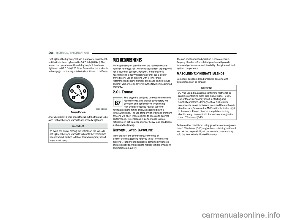
First tighten the lug nuts/bolts in a star pattern until each
nut/bolt has been tightened to 14.7 ft-lb (20 N·m). Then
repeat the operation until each lug nut/bolt has been
tightened to 88.5 ft-lb (120 N·m). Ensure that the socket is
fully engaged on the lug nut/bolt (do not insert it halfway).
Torque Pattern
After 25 miles (40 km), check the lug nut/bolt torque to be
sure that all the lug nuts/bolts are properly tightened.
FUEL REQUIREMENTS
While operating on gasoline with the required octane
number, hearing a light knocking sound from the engine is
not a cause for concern. However, if the engine is
heard making a heavy knocking sound, see a dealer
immediately. Use of gasoline with a lower than
recommended octane number can cause engine failure
and may void or not be covered by the New Vehicle Limited
Warranty.
2.0L ENGINE
This engine is designed to meet all emissions
requirements, and provide satisfactory fuel
economy and performance, when using
high-quality unleaded regular gasoline
having an octane rating of 87, as specified by the
(R+M)/2 method. The use of 91 or higher octane premium
gasoline will allow these engines to operate to optimal
performance. This increase in performance is most
noticeable in hot weather or under heavy load conditions
such as while towing.
REFORMULATED GASOLINE
Many areas of the country require the use of
cleaner-burning gasoline referred to as “reformulated
gasoline”. Reformulated gasoline contains oxygenates
and are specifically blended to reduce vehicle emissions
and improve air quality. The use of reformulated gasoline is recommended.
Properly blended reformulated gasoline will provide
improved performance and durability of engine and fuel
system components.
GASOLINE/OXYGENATE BLENDS
Some fuel suppliers blend unleaded gasoline with
oxygenates such as ethanol.
Problems that result from using gasoline containing more
than 15% ethanol (E-15) or gasoline containing methanol
are not the responsibility of the manufacturer and may
void the New Vehicle Limited Warranty.
WARNING!
To avoid the risk of forcing the vehicle off the jack, do
not tighten the lug nuts/bolts fully until the vehicle has
been lowered. Failure to follow this warning may result
in personal injury.
CAUTION!
DO NOT use E-85, gasoline containing methanol, or
gasoline containing more than 15% ethanol (E-15).
Use of these blends may result in starting and
drivability problems, damage critical fuel system
components, cause emissions to exceed the applicable
standard, and/or cause the Malfunction Indicator Light
to illuminate. Please observe pump labels as they
should clearly communicate if a fuel contains greater
than 15% ethanol (E-15).
23_GG_OM_EN_USC_t.book Page 266
Page 283 of 288
281
Headlight Switch ........................................................40
Headlights ..................................................................40
Headlights On With Wipers .......................................41
High Beam...........................................................40
, 78
High Beam/Low Beam Select ...................................40
Hood Open .................................................................73
Intensity Control ..................................................42
, 43
Interior ........................................................................42
LaneSense .................................................................75
Liftgate Open.............................................................. 73
Lights On Reminder ...................................................41
Low Fuel .....................................................................75
Malfunction Indicator (Check Engine) ...................... 75
Oil Pressure ................................................................73
Oil Temperature .........................................................73
Park ............................................................................77
Passing ....................................................................... 41
Seat Belt Reminder ...................................................73
Security Alarm ............................................................73
Service ..................................................................... 246
Service Forward Collision Warning ...........................75
Service Stop Start ...................................................... 75
Stop Start Active ........................................................77
Tire Pressure Monitoring (TPMS) .................... 75
, 165
Towing Hook Breakdown...........................................76
Traction Control ...................................................... 157
Transmission Temperature .......................................76
Turn Signals ....................................... 40
, 42, 77, 201
Vanity Mirror............................................................... 34
Loading Vehicle ............................................................ 120 Tires ......................................................................... 251
Locks Auto Unlock ................................................................25
Child Protection .........................................................25
Power Door .................................................................22 Low Tire Pressure System ............................................165
Lubrication, Body .......................................................... 230
Lug Nuts/Bolts .............................................................. 265
MMaintenance ................................................................... 58
Maintenance Free Battery ...........................................227
Maintenance Schedule ................................................ 223
Malfunction Indicator Light (Check Engine) .................. 75Manual Service .....................................................................274
Memory Feature (Memory Seats) .................................. 27
Memory Seat ................................................................... 27 Memory Settings............................................................. 27
Methanol ....................................................................... 266
Mirrors ............................................................................. 34 Automatic Dimming................................................... 34
Heated................................................................. 34
, 36
Outside ................................................................ 34, 35
Rearview ...........................................................34, 203
Vanity.......................................................................... 34
Modifications/Alterations Vehicle.......................................................................... 8
Monitor, Tire Pressure System..................................... 165
Mopar Parts .................................................................. 273
Multi-Function Control Lever .......................................... 40
NNew Vehicle Break-In Period .......................................... 82
OOccupant Restraints ..................................................... 168
Octane Rating, Gasoline (Fuel) .......................... 266, 269
Oil Change Reset
b
...................................................... 68 Oil Filter, Change .......................................................... 228
Oil Filter, Selection ....................................................... 228
Oil Pressure Light ........................................................... 73
Oil, Engine ............................................................ 228
, 269
Capacity ................................................................... 268
Checking .................................................................. 227
Dipstick .................................................................... 227
Disposal ................................................................... 228
Filter ......................................................................... 228
Filter Disposal.......................................................... 228
Identification Logo .................................................. 228
Materials Added To ................................................. 228 Pressure Warning Light ............................................ 73
Recommendation...........................................228
, 268
Synthetic .................................................................. 228
Viscosity ................................................................... 268
Onboard Diagnostic System .......................................... 78
Operator Manual Owner's Manual ...................................................... 274
Outlet Power ......................................................................... 52
Outside Rearview Mirrors ....................................... 34
, 35
Overheating, Engine ..................................................... 218
PPaint Care ..................................................................... 262
Panic Alarm ..................................................................... 13 Parking Brake ................................................................. 82
ParkSense Front And Rear ........................................................ 105
ParkSense Active Park Assist ...................................... 108
ParkSense System ....................................................... 105
Pedestrian Warning System ........................................ 164
Performance .......................................................... 69
, 152
11
23_GG_OM_EN_USC_t.book Page 281