audio DODGE HORNET 2023 Owners Manual
[x] Cancel search | Manufacturer: DODGE, Model Year: 2023, Model line: HORNET, Model: DODGE HORNET 2023Pages: 288, PDF Size: 14.2 MB
Page 7 of 288
5
TRAILER TOWING............................................................. 121Common Towing Definitions .................................... 121
Trailer Towing Weights
(Maximum Trailer Weight Ratings) .......................... 122Trailer And Tongue Weight ....................................... 123
Towing Requirements .............................................. 123
Towing Tips ............................................................... 125
RECREATIONAL TOWING (BEHIND MOTORHOME) .... 126 Towing This Vehicle Behind Another Vehicle .......... 126
Recreational Towing ................................................. 127
DRIVING TIPS ................................................................... 127 Driving On Slippery Surfaces.................................... 127
Driving Through Water ............................................. 128
MULTIMEDIA
UCONNECT SYSTEMS ..................................................... 129
CYBERSECURITY ............................................................. 129
UCONNECT SETTINGS ..................................................... 130Customer Programmable Features ......................... 130
STEERING WHEEL AUDIO CONTROLS —
IF EQUIPPED .................................................................... 150 Steering Wheel Rotary Control ................................. 150Controls on Central Tunnel....................................... 151
MY CAR ............................................................................. 151
PERFORMANCE PAGES .................................................. 152 Technical Gauges...................................................... 152Consumption History ................................................ 152Accessory Gauges ..................................................... 153
RADIO OPERATION AND MOBILE PHONES .................. 153 Regulatory And Safety Information .......................... 153
SAFETY
SAFETY FEATURES .......................................................... 154Anti-Lock Brake System (ABS) ................................ 154
Electronic Brake Control (EBC) System .................. 155
AUXILIARY DRIVING SYSTEMS ...................................... 159 Blind Spot Monitoring (BSM) —
If Equipped ................................................................ 159Forward Collision Warning (FCW)
With Mitigation — If Equipped .................................. 162
Tire Pressure Monitoring System (TPMS) ............... 165
OCCUPANT RESTRAINT SYSTEMS ............................... 168 Occupant Restraint Systems Features ................... 168
Important Safety Precautions .................................. 168
Seat Belt Systems .................................................... 169
Supplemental Restraint Systems (SRS).................. 175
Child Restraints ........................................................ 188
SAFETY TIPS .................................................................... 199 Transporting Passengers ......................................... 199
Transporting Pets .................................................... 199
Connected Vehicles .................................................. 199Safety Checks You Should Make Inside
The Vehicle ............................................................... 200Periodic Safety Checks You Should Make Outside
The Vehicle ................................................................ 201Exhaust Gas .............................................................. 202
Carbon Monoxide Warnings ..................................... 202
IN CASE OF EMERGENCY
HAZARD WARNING FLASHERS ......................................203
SOS SYSTEM — IF EQUIPPED.......................................... 203
JACKING AND TIRE CHANGING —
IF EQUIPPED
b
...............................................................206
Preparations For Jacking ......................................... 206
Jack And Tools Location/Spare Tire Stowage —
If Equipped................................................................. 207
Jacking Instructions ................................................. 208
TIRE INFLATOR KIT — IF EQUIPPED
b
........................211
Description................................................................. 211
Inflation Procedure.................................................... 212
Checking And Restoring Tire Pressure..................... 214
Sealant Cartridge Replacement ............................... 214
JUMP STARTING ...............................................................215 Preparations For Jump Start..................................... 215
Jump Starting Procedure .......................................... 216
REFUELING IN EMERGENCY ........................................... 217
IF YOUR ENGINE OVERHEATS ........................................218
GEAR SELECTOR OVERRIDE .......................................... 218
FREEING A STUCK VEHICLE ........................................... 219
TOWING A DISABLED VEHICLE.......................................220 Without The Key Fob ................................................. 221
All-Wheel Drive (AWD) Models ................................. 221
Tow Eye — If Equipped .............................................. 221
ENHANCED ACCIDENT RESPONSE
SYSTEM (EARS) ...............................................................222
EVENT DATA RECORDER (EDR)......................................222
23_GG_OM_EN_USC_t.book Page 5
Page 54 of 288
52GETTING TO KNOW YOUR VEHICLE
By using a USB cable to connect an external device:
The device can be played on the vehicle’s sound
system, providing the artist, track title, and album infor -
mation on the radio display.
NOTE:Depending on track configuration, track information may
not be present on the radio display.
The device can be controlled using the radio buttons to
play, and browse the contents of the device.
The audio device battery charges when plugged into
the USB port.
The second row USB ports can be used to charge an
external device. These ports are charge only.
Charge Only Rear USB Ports
Both the front and rear USB C port have the ability for fast
charging. They are Power Delivery 3.0 and can provide
charging up to 40W.
NOTE:Charge unsupported devices with the Charge Only USB
ports. If an unsupported device is plugged into a Media
USB port, a message will display on the touchscreen that
the device is not supported by the system.
POWER OUTLETS — IF EQUIPPED
Your vehicle may be equipped with 12 Volt (13 Amp)
power outlets that can be used to power cellular phones,
small electronics and other low powered electrical
accessories.
The Instrument Panel Power Outlet is located in the
storage compartment under the climate control buttons. It
will only operate when the ignition is in the ON/RUN
position.
Power Outlet
NOTE:
Do not connect devices, with a power rating higher than
180 W, to the outlet. Do not use power adapters that
do not fit the outlet as this may damage it.
All accessories connected to the battery powered
outlets should be removed or turned off when the
vehicle is not in use to protect the battery against
discharge.
If equipped, a power outlet is located in the rear cargo
area.
Rear Cargo Area Power Outlet — If Equipped
NOTE:
The rear cargo area power outlet can be switched from
ignition powered to battery powered. See an authorized
dealer for details.
1 — Type C USB Port
2 — Type A USB Port
23_GG_OM_EN_USC_t.book Page 52
Page 72 of 288
70GETTING TO KNOW YOUR INSTRUMENT PANEL
DRIVER ASSIST
The instrument cluster display displays the current
Adaptive Cruise Control (ACC) and Lane Keep Assist (LKA)
system settings. The information displayed depends on
ACC system status.
The Instrument Cluster Display shows the status and
settings of the driving assistance Adaptive Cruise Control,
Lane Keep Assist and Active Driving Assist systems. Any
instant notifications are displayed via a pop-up screen.
The instrument cluster display displays the current LKA
system settings. The information displayed depends on
Lane Keep Assist system status and the conditions that
need to be met
Úpage 113.
STORED MESSAGES
Turn the Thumbwheel up and down until the Stored
Messages menu option is highlighted. Press the
Thumbwheel to enter and exit the Stored Messages.
Messages shown on the display via popup screens are
stored as long as they remain valid. You can view them
later in the central area of the “Messages” screen.
If multiple messages are present:
Press the Thumbwheel to access the message list.
Scroll through the messages by turning the Thumb -
wheel up or down. The presence or previous or next
message is indicated by gray dots.
BATTERY SAVER ON/BATTERY SAVER
M
ODE MESSAGE — ELECTRICAL LOAD
R
EDUCTION ACTIONS — IF EQUIPPED
This vehicle is equipped with an Intelligent Battery Sensor
(IBS) to perform additional monitoring of the electrical
system and status of the vehicle battery.
In cases when the IBS detects charging system failure, or
the vehicle battery conditions are deteriorating, electrical
load reduction actions will take place to extend the driving
time and distance of the vehicle. This is done by reducing
power to or turning off non-essential electrical loads.
Load reduction is only active when the engine is running.
It will display a message if there is a risk of battery
depletion to the point where the vehicle may stall due to
lack of electrical supply, or will not restart after the current
drive cycle.
These messages indicate the vehicle battery has a low
state of charge and continues to lose electrical charge at
a rate that the charging system cannot sustain.
NOTE:
The charging system is independent from load reduc -
tion. The charging system performs a diagnostic on the
charging system continuously.
If the Battery Charge Warning Light is on it may indicate
a problem with the charging system
Úpage 72. The electrical loads that may be switched off (if equipped),
and vehicle functions which can be effected by load
reduction:
Heated Seat/Vented Seats/Heated Wheel
Heated/Cooled Cup Holders — If Equipped
Rear Defroster And Heated Mirrors
HVAC System
150W Power Inverter System
Audio and Telematics System
Loss of the battery charge may indicate one or more of the
following conditions:
The charging system cannot deliver enough electrical
power to the vehicle system because the electrical
loads are larger than the capability of charging system.
The charging system is still functioning properly.
Turning on all possible vehicle electrical loads (e.g.
HVAC to max settings, exterior and interior lights, over -
loaded power outlets +12 Volts, 150W, USB ports)
during certain driving conditions (city driving, towing,
frequent stopping).
Installing options like additional lights, upfitter elec -
trical accessories, audio systems, alarms and similar
devices.
Unusual driving cycles (short trips separated by long
parking periods).
The vehicle was parked for an extended period of time
(weeks, months).
23_GG_OM_EN_USC_t.book Page 70
Page 73 of 288
GETTING TO KNOW YOUR INSTRUMENT PANEL71
The battery was recently replaced and was not charged
completely.
The battery was discharged by an electrical load left on
when the vehicle was parked.
The battery was used for an extended period with the
engine not running to supply radio, lights, chargers,
+12 Volts portable appliances like vacuum cleaners,
game consoles and similar devices.
What to do when an electrical load reduction action
message is present (“Battery Saver On” or
“Battery Saver Mode”)
During a trip:
Reduce power to unnecessary loads if possible:
Turn off redundant lights (interior or exterior)
Check what may be plugged into power outlets
+12 Volts, 150W, USB ports
Check HVAC settings (blower, temperature)
Check the audio settings (volume)
After a trip:
Check if any aftermarket equipment was installed
(additional lights, upfitter electrical accessories,
audio systems, alarms) and review specifications if any
(load and Ignition Off Draw currents).
Evaluate the latest driving cycles (distance, driving
time and parking time).
The vehicle should have service performed if the
message is still present during consecutive trips and
the evaluation of the vehicle and driving pattern did not
help to identify the cause.WARNING LIGHTS AND MESSAGES
The warning/indicator lights will illuminate in the
instrument panel together with a dedicated message and/
or acoustic signal when applicable. These indications are
indicative and precautionary and as such must not be
considered as exhaustive and/or alternative to the
information contained in the Owner’s Manual, which you
are advised to read carefully in all cases. Always refer to
the information in this chapter in the event of a failure
indication. All active telltales will display first if applicable.
The system check menu may appear different based upon
equipment options and current vehicle status. Some
telltales are optional and may not appear.
RED WARNING LIGHTS
Air Bag Warning Light
This warning light will illuminate to indicate a
fault with the air bag, and will turn on for four to
eight seconds as a bulb check when the
ignition is placed in the ON/RUN position. This
light will illuminate with a single chime when a fault with
the air bag has been detected, it will stay on until the fault
is cleared. If the light is either not on during startup, stays
on, or turns on while driving, have the system inspected at
an authorized dealer as soon as possible.
Brake Warning Light
This warning light monitors various brake
functions, including brake fluid level and
parking brake application. If the brake light
turns on it may indicate that the parking brake
is applied, that the brake fluid level is low, or that there is
a problem with the Anti-Lock Brake System reservoir. If the light remains on when the parking brake has been
disengaged, and the fluid level is at the full mark on the
master cylinder reservoir, it indicates a possible brake
hydraulic system malfunction or that a problem with the
Brake Booster has been detected by the Anti-Lock Brake
System (ABS) / Electronic Stability Control (ESC) system.
In this case, the light will remain on until the condition has
been corrected. If the problem is related to the brake
booster, the ABS pump will run when applying the brake,
and a brake pedal pulsation may be felt during each stop.
The dual brake system provides a reserve braking capacity
in the event of a failure to a portion of the hydraulic
system. A leak in either half of the dual brake system is
indicated by the Brake Warning Light, which will turn on
when the brake fluid level in the master cylinder has
dropped below a specified level.
The light will remain on until the cause is corrected.
NOTE:The light may flash momentarily during sharp cornering
maneuvers, which change fluid level conditions. The
vehicle should have service performed, and the brake
fluid level checked.
If brake failure is indicated, immediate repair is necessary.
WARNING!
Driving a vehicle with the red brake light on is
dangerous. Part of the brake system may have failed.
It will take longer to stop the vehicle. You could have a
collision. Have the vehicle checked immediately.
3
23_GG_OM_EN_USC_t.book Page 71
Page 135 of 288
MULTIMEDIA133
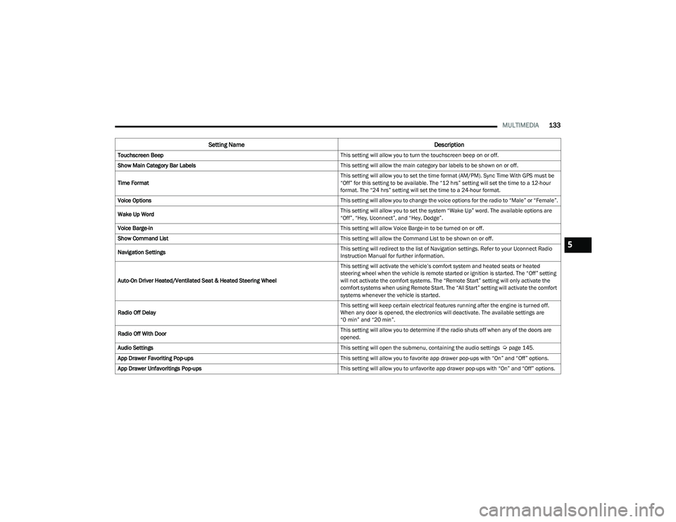
Touchscreen Beep This setting will allow you to turn the touchscreen beep on or off.
Show Main Category Bar Labels This setting will allow the main category bar labels to be shown on or off.
Time Format This setting will allow you to set the time format (AM/PM). Sync Time With GPS must be
“Off” for this setting to be available. The “12 hrs” setting will set the time to a 12-hour
format. The “24 hrs” setting will set the time to a 24-hour format.
Voice Options This setting will allow you to change the voice options for the radio to “Male” or “Female”.
Wake Up Word This setting will allow you to set the system “Wake Up” word. The available options are
“Off”, “Hey, Uconnect”, and “Hey, Dodge”.
Voice Barge-in This setting will allow Voice Barge-in to be turned on or off.
Show Command List This setting will allow the Command List to be shown on or off.
Navigation Settings This setting will redirect to the list of Navigation settings. Refer to your Uconnect Radio
Instruction Manual for further information.
Auto-On Driver Heated/Ventilated Seat & Heated Steering Wheel This setting will activate the vehicle’s comfort system and heated seats or heated
steering wheel when the vehicle is remote started or ignition is started. The “Off” setting
will not activate the comfort systems. The “Remote Start” setting will only activate the
comfort systems when using Remote Start. The “All Start” setting will activate the comfort
systems whenever the vehicle is started.
Radio Off Delay This setting will keep certain electrical features running after the engine is turned off.
When any door is opened, the electronics will deactivate. The available settings are
“0 min” and “20 min”.
Radio Off With Door This setting will allow you to determine if the radio shuts off when any of the doors are
opened.
Audio Settings This setting will open the submenu, containing the audio settings
Úpage 145.
App Drawer Favoriting Pop-ups This setting will allow you to favorite app drawer pop-ups with “On” and “Off” options.
App Drawer Unfavoritings Pop-ups This setting will allow you to unfavorite app drawer pop-ups with “On” and “Off” options.
Setting NameDescription
5
23_GG_OM_EN_USC_t.book Page 133
Page 140 of 288
138MULTIMEDIA
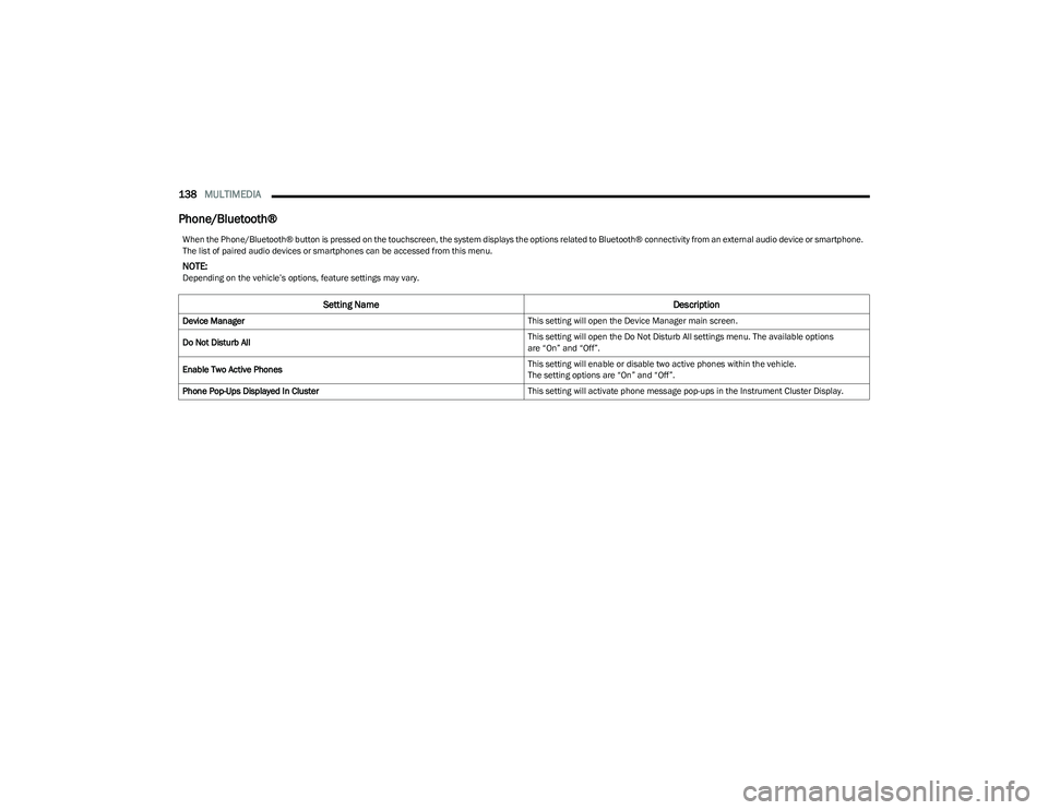
Phone/Bluetooth®
When the Phone/Bluetooth® button is pressed on the touchscreen, the system displays the options related to Bluetooth® connectivity from an external audio device or smartphone.
The list of paired audio devices or smartphones can be accessed from this menu.
NOTE:Depending on the vehicle’s options, feature settings may vary.
Setting Name Description
Device Manager This setting will open the Device Manager main screen.
Do Not Disturb All This setting will open the Do Not Disturb All settings menu. The available options
are “On” and “Off”.
Enable Two Active Phones This setting will enable or disable two active phones within the vehicle.
The setting options are “On” and “Off”.
Phone Pop-Ups Displayed In Cluster This setting will activate phone message pop-ups in the Instrument Cluster Display.
23_GG_OM_EN_USC_t.book Page 138
Page 147 of 288
MULTIMEDIA145
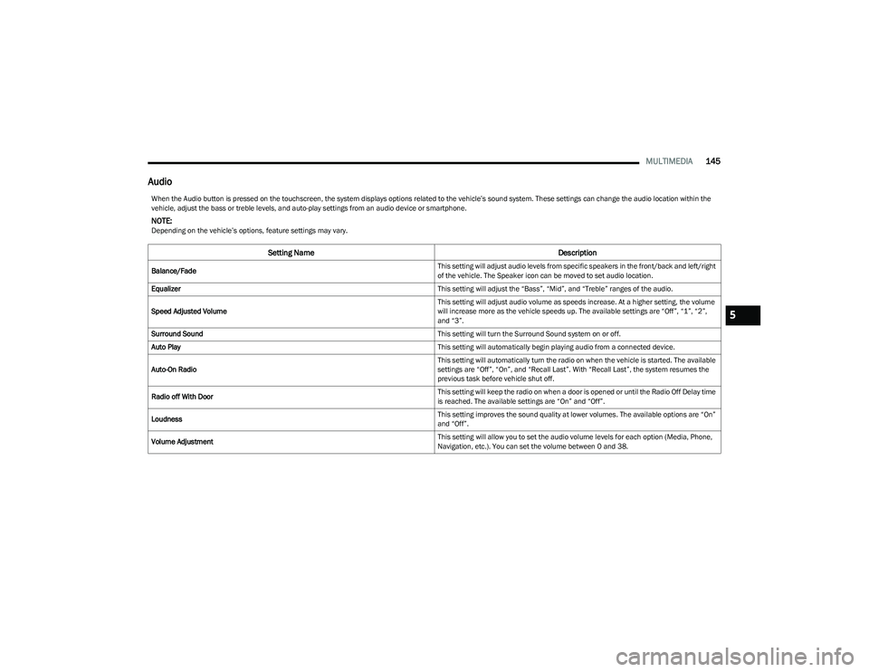
Audio
When the Audio button is pressed on the touchscreen, the system displays options related to the vehicle’s sound system. These settings can change the audio location within the
vehicle, adjust the bass or treble levels, and auto-play settings from an audio device or smartphone.
NOTE:Depending on the vehicle’s options, feature settings may vary.
Setting Name Description
Balance/Fade This setting will adjust audio levels from specific speakers in the front/back and left/right
of the vehicle. The Speaker icon can be moved to set audio location.
Equalizer This setting will adjust the “Bass”, “Mid”, and “Treble” ranges of the audio.
Speed Adjusted Volume This setting will adjust audio volume as speeds increase. At a higher setting, the volume
will increase more as the vehicle speeds up. The available settings are “Off”, “1”, “2”,
and “3”.
Surround Sound This setting will turn the Surround Sound system on or off.
Auto Play This setting will automatically begin playing audio from a connected device.
Auto-On Radio This setting will automatically turn the radio on when the vehicle is started. The available
settings are “Off”, “On”, and “Recall Last”. With “Recall Last”, the system resumes the
previous task before vehicle shut off.
Radio off With Door This setting will keep the radio on when a door is opened or until the Radio Off Delay time
is reached. The available settings are “On” and “Off”.
Loudness This setting improves the sound quality at lower volumes. The available options are “On”
and “Off”.
Volume Adjustment This setting will allow you to set the audio volume levels for each option (Media, Phone,
Navigation, etc.). You can set the volume between 0 and 38.
5
23_GG_OM_EN_USC_t.book Page 145
Page 152 of 288
150MULTIMEDIA
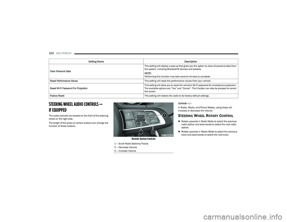
STEERING WHEEL AUDIO CONTROLS —
IF EQUIPPED
The audio controls are located on the front of the steering
wheel on the right side.
The length of the press on certain buttons can change the
function of these buttons.
Remote System Controls
Controls + / -
In Radio, Media, and Phone Modes, using these will
increase or decrease the volume.
STEERING WHEEL ROTARY CONTROL
Rotate upwards in Radio Mode to select the previous
radio station and downwards to select the next radio
station.
Rotate upwards in Media Mode to select the previous
track and downwards to select the next track.
Clear Personal Data
This setting will display a pop-up that gives you the option to clear all personal data from
the system, including Bluetooth® devices and presets.
NOTE:Performing this function may take several minutes to complete.
Reset Performance Values This setting will reset the performance values from your vehicle.
Reset Wi-Fi Password For Projection This setting will allow you to reset the vehicle’s Wi-Fi password for smartphone projection.
The available options are “Yes” and “Cancel”. The X button can also be pressed to cancel
the screen.
Factory Reset This setting will restore the radio to its factory default settings.
Setting NameDescription
1 — Scroll Radio Stations/Tracks
2 — Decrease Volume
3 — Increase Volume
23_GG_OM_EN_USC_t.book Page 150
Page 153 of 288
MULTIMEDIA151
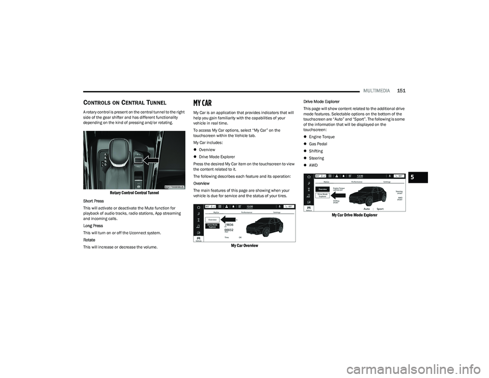
CON TR O LS O N CEN TR AL TUN NEL
A rotary control is present on the central tunnel to the right
side of the gear shifter and has different functionality
depending on the kind of pressing and/or rotating.
Rotary Control Central Tunnel
Short Press
This will activate or deactivate the Mute function for
playback of audio tracks, radio stations, App streaming
and incoming calls.
Long Press
This will turn on or off the Uconnect system.
Rotate
This will increase or decrease the volume.
MY CAR
My Car is an application that provides indicators that will
help you gain familiarity with the capabilities of your
vehicle in real time.
To access My Car options, select “My Car” on the
touchscreen within the Vehicle tab.
My Car includes:
Overview
Drive Mode Explorer
Press the desired My Car item on the touchscreen to view
the content related to it.
The following describes each feature and its operation:
Overview
The main features of this page are showing when your
vehicle is due for service and the status of your tires.
My Car Overview
Drive Mode Explorer
This page will show content related to the additional drive
mode features. Selectable options on the bottom of the
touchscreen are “Auto” and “Sport”. The following is some
of the information that will be displayed on the
touchscreen:
Engine Torque
Gas Pedal
Shifting
Steering
AWD
My Car Drive Mode Explorer
5
23_GG_OM_EN_USC_t.book Page 151
Page 206 of 288
204IN CASE OF EMERGENCY
SOS Call
1. Press or hold the SOS Call button on the overhead
console.
NOTE:In case the SOS Call button is pushed in error, there will be
a 10 second delay before the SOS Call system initiates a
call to an SOS operator. To cancel the SOS Call
connection, push the SOS call button on the overhead
console or press the cancellation button on the Device
Screen. Termination of the SOS Call will turn off the green
LED light on the overhead console.
2. The LED light located next to the SOS button on the overhead console will turn green once a connection
to a SOS operator has been made.
3. Once a connection between the vehicle and an SOS operator is made, the SOS Call system may transmit
the following important vehicle information to a SOS
operator:
Indication that the occupant placed an SOS Call
The vehicle brand
The last known GPS coordinates of the vehicle
4. You should be able to speak with the SOS operator through the vehicle audio system to determine if
additional assistance is needed.
NOTE:
Your vehicle may be transmitting data as autho -
rized by the subscriber.
Once a connection is made between the vehicle’s
SOS Call system and the SOS operator, the SOS
operator may be able to open a voice connection
with the vehicle to determine if additional assis -
tance is needed. Once the SOS operator opens a
voice connection with the vehicle’s SOS Call
system, the operator should be able to speak with
you or other vehicle occupants and hear sounds
occurring in the vehicle. The vehicle’s SOS Call
system will attempt to remain connected with the
SOS operator until the SOS operator terminates
the connection.
5. The SOS operator may attempt to contact appropriate emergency responders and provide them with
important vehicle information and GPS coordinates.
WARNING!
ALWAYS obey traffic laws and pay attention to the road.
ALWAYS drive safely with your hands on the steering
wheel. You have full responsibility and assume all risks
related to the use of the features and applications in
this vehicle. Only use the features and applications
when it is safe to do so. Failure to do so may result in an
accident involving serious injury or death.
WARNING!
If anyone in the vehicle could be in danger (e.g., fire
or smoke is visible, dangerous road conditions or
location), do not wait for voice contact from an Emer -
gency Services Agent. All occupants should exit the
vehicle immediately and move to a safe location.
Never place anything on or near the vehicle’s oper -
able network and GPS antennas. You could prevent
operable network and GPS signal reception, which
can prevent your vehicle from placing an emergency
call. An operable network and GPS signal reception is
required for the SOS Call system to function properly.
The SOS Call system is embedded into the vehicle’s
electrical system. Do not add aftermarket electrical
equipment to the vehicle’s electrical system. This
may prevent your vehicle from sending a signal to
initiate an emergency call. To avoid interference that
can cause the SOS Call system to fail, never add
aftermarket equipment (e.g., two-way mobile radio,
CB radio, data recorder, etc.) to your vehicle’s elec -
trical system or modify the antennas on your vehicle.
IF YOUR VEHICLE LOSES BATTERY POWER FOR ANY
REASON (INCLUDING DURING OR AFTER AN ACCI -
DENT), THE DODGE CONNECT FEATURES, APPS AND
SERVICES, AMONG OTHERS, WILL NOT OPERATE.
Modifications to any part of the SOS Call system
could cause the air bag system to fail when you need
it. You could be injured if the air bag system is not
there to help protect you.
23_GG_OM_EN_USC_t.book Page 204