automatic transmission DODGE HORNET 2023 Owners Manual
[x] Cancel search | Manufacturer: DODGE, Model Year: 2023, Model line: HORNET, Model: DODGE HORNET 2023Pages: 288, PDF Size: 14.2 MB
Page 6 of 288
4
STARTING AND OPERATING
STARTING THE ENGINE ......................................................80
Normal Starting ........................................................... 80
Cold Weather Operation
(Below –22°F Or −30°C) .......................................... 81
Extended Park Starting............................................... 81
After Starting — Warming Up The Engine .................. 81
If Engine Fails To Start ............................................... 81
Stopping The Engine ................................................... 82
ENGINE BREAK-IN RECOMMENDATIONS .......................82
PARK BRAKE ....................................................................... 82 Electric Park Brake (EPB) .......................................... 82
AUTOMATIC TRANSMISSION .............................................85 Ignition Park Interlock................................................. 86
Brake/Transmission Shift Interlock (BTSI)
System ......................................................................... 86
9-Speed Automatic Transmission ............................. 86
ALL-WHEEL DRIVE (AWD) ..................................................88
SPORT MODE — IF EQUIPPED ...........................................88
POWER STEERING ..............................................................88
STOP/START SYSTEM — IF EQUIPPED.............................89 Autostop Mode ............................................................ 89
Possible Reasons The Engine Does Not Autostop.... 89
To Start The Engine While In Autostop Mode............ 90
To Manually Turn Off The Stop/Start System ........... 90
To Manually Turn On The Stop/Start System............ 90
System Malfunction .................................................... 90 ACTIVE SPEED LIMITER — IF EQUIPPED .......................... 90
Activation...................................................................... 91
Exceeding The Set Speed ........................................... 91
Deactivation ................................................................. 91
INTELLIGENT SPEED ASSIST (ISA) —
IF EQUIPPED ........................................................................ 91 Activation...................................................................... 92
Sign Capture Modes .................................................... 92
Exceeding The Set Speed ........................................... 92
Deactivation ................................................................. 92
CRUISE CONTROL SYSTEMS ............................................. 92 Adaptive Cruise Control (ACC)..................................... 92
TRAFFIC SIGN RECOGNITION —
IF EQUIPPED ........................................................................ 99 Activation/Deactivation ............................................... 99
Traffic Sign Recognition Modes .................................. 99
Indications On The Display....................................... 100
INTELLIGENT ADAPTIVE CRUISE CONTROL —
IF EQUIPPED ..................................................................... 100 Activation/Deactivation ............................................ 100
ACTIVE DRIVING ASSIST SYSTEM —
IF EQUIPPED ..................................................................... 101 Operation................................................................... 101
Turning Active Driving Assist On Or Off ................... 102
Indications On The Display....................................... 103
Minimum Risk Maneuver ......................................... 104
System Status ........................................................... 104
System Operation/Limitations................................. 104 PARKSENSE FRONT/REAR PARK ASSIST SYSTEM —
IF EQUIPPED ....................................................................105
ParkSense Sensors ................................................... 105
ParkSense Warning Display...................................... 105ParkSense Display .................................................... 105
Enabling And Disabling ParkSense .......................... 106
Service The ParkSense Park Assist System ............ 106
Cleaning The ParkSense System ............................. 106
ParkSense System Usage Precautions .................... 106
Side Distance Warning (SDW) System..................... 107
PARKSENSE ACTIVE PARK ASSIST SYSTEM —
IF EQUIPPED......................................................................108 Enabling And Disabling The ParkSense Active
Park Assist System .................................................... 109
Parallel/Perpendicular Parking Space Assistance
Operation ................................................................... 110Exiting The Parking Space ........................................ 112
LANESENSE — IF EQUIPPED .......................................... 113 LaneSense Operation ............................................... 113Turning LaneSense On Or Off ................................... 114
LaneSense Warning Message .................................. 114
Changing LaneSense Status .................................... 116
PARKVIEW REAR BACK UP CAMERA ............................ 116
SURROUND VIEW CAMERA SYSTEM —
IF EQUIPPED......................................................................117
REFUELING THE VEHICLE ................................................119
VEHICLE LOADING ...........................................................120 Certification Label ..................................................... 120
23_GG_OM_EN_USC_t.book Page 4
Page 8 of 288
6
SERVICING AND MAINTENANCE
SCHEDULED SERVICING ................................................ 223
Maintenance Plan ..................................................... 224
ENGINE COMPARTMENT................................................. 226 2.0L Engine .............................................................. 226Checking Oil Level ..................................................... 227
Adding Washer Fluid ................................................ 227Maintenance-Free Battery........................................ 227Pressure Washing ..................................................... 228
VEHICLE MAINTENANCE ................................................. 228 Engine Oil................................................................... 228
Engine Oil Filter ......................................................... 228
Engine Air Cleaner Filter ........................................... 229
Air Conditioner Maintenance ................................... 229
Body Lubrication ....................................................... 230Wiper Blades ............................................................ 230
Exhaust System ........................................................ 232
Cooling System.......................................................... 233
Brake System ........................................................... 236
Automatic Transmission —
If Equipped ................................................................ 236
Fuses ......................................................................... 237
Bulb Replacement ................................................... 246
TIRES ................................................................................ 246 Tire Safety Information ............................................ 246
Tires — General Information .................................... 254
Tire Types................................................................... 257
Spare Tires — If Equipped ........................................ 258Snow Traction Devices ............................................ 259
Tire Rotation Recommendations ............................ 260 DEPARTMENT OF TRANSPORTATION UNIFORM
TIRE QUALITY GRADES .................................................. 260
Treadwear ................................................................. 260Traction Grades ........................................................ 261Temperature Grades ................................................ 261
STORING THE VEHICLE ................................................... 261
BODYWORK ...................................................................... 262 Protection From Atmospheric Agents ...................... 262Body And Underbody Maintenance ......................... 262
Preserving The Bodywork ......................................... 263
INTERIORS ....................................................................... 263 Seats And Fabric Parts ............................................. 263
Plastic And Coated Parts .......................................... 264Leather Surfaces ...................................................... 264
Glass Surfaces ......................................................... 264
TECHNICAL SPECIFICATIONS
VEHICLE IDENTIFICATION NUMBER (VIN)..................... 265
BRAKE SYSTEM .............................................................. 265
WHEEL AND TIRE TORQUE SPECIFICATIONS .............. 265 Torque Specifications ............................................... 265
FUEL REQUIREMENTS ..................................................... 266 2.0L Engine ............................................................... 266Reformulated Gasoline ........................................... 266Gasoline/Oxygenate Blends ................................... 266E-85 Usage In Non-Flex Fuel Vehicles ..................... 267CNG And LP Fuel System Modifications.................. 267
Methylcyclopentadienyl Manganese
Tricarbonyl (MMT) In Gasoline ................................. 267
Materials Added To Fuel .......................................... 267Fuel System Cautions ............................................... 267 FLUID CAPACITIES ...........................................................268
ENGINE FLUIDS AND LUBRICANTS ................................269
CHASSIS FLUIDS AND LUBRICANTS ..............................269
CUSTOMER ASSISTANCE
SUGGESTIONS FOR OBTAINING SERVICE FOR
YOUR VEHICLE ................................................................. 270 Prepare For The Appointment .................................. 270
Prepare A List ............................................................ 270Be Reasonable With Requests ................................. 270
IF YOU NEED ASSISTANCE .............................................270 Roadside Assistance ................................................. 271
FCA US LLC Customer Center ................................... 272
FCA Canada Inc. Customer Care .............................. 272
Mexico ........................................................................ 272
Puerto Rico And US Virgin Islands............................ 272
Customer Assistance For The Hearing Or
Speech Impaired (TDD/TTY) ..................................... 272
Service Contract ....................................................... 272
WARRANTY INFORMATION.............................................273
MOPAR® PARTS ..............................................................273
REPORTING SAFETY DEFECTS ......................................273 In The 50 United States And Washington, D.C........ 273
In Canada................................................................... 273
PUBLICATION ORDER FORMS .......................................274
CHANGE OF OWNERSHIP OR ADDRESS.......................274
GENERAL INFORMATION................................................. 275
23_GG_OM_EN_USC_t.book Page 6
Page 64 of 288
62GETTING TO KNOW YOUR VEHICLE
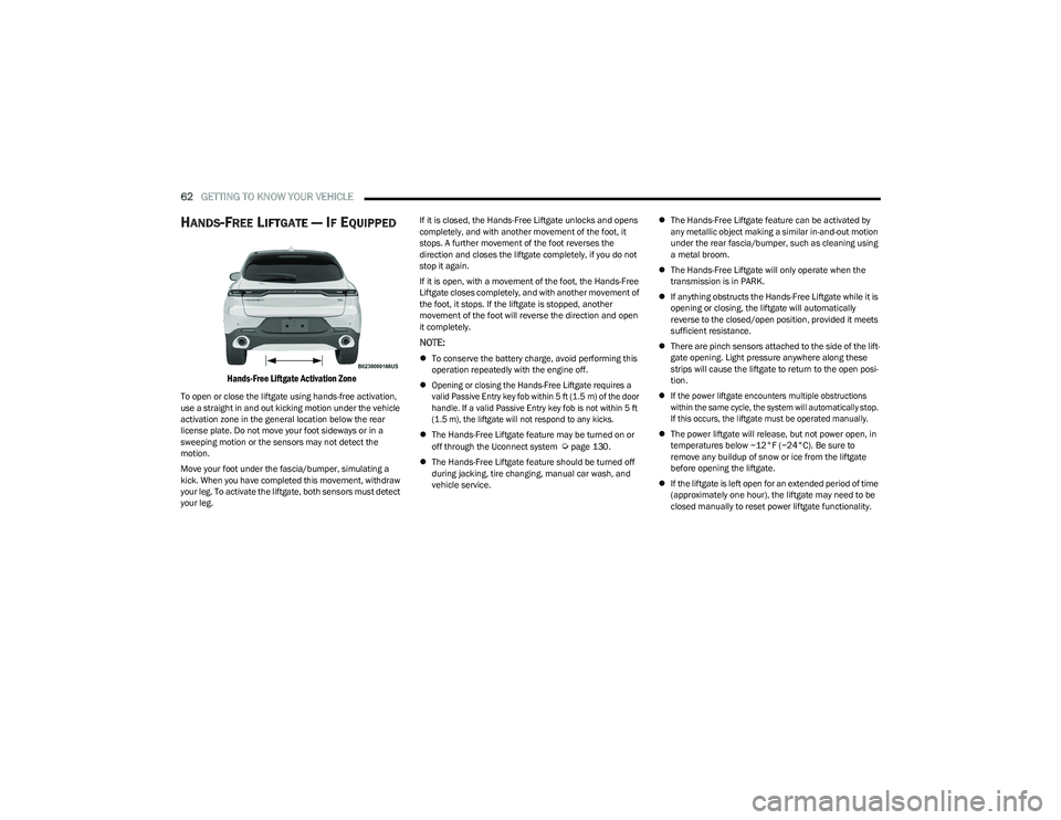
HANDS-FREE LIFTGATE — IF EQUIPPED
Hands-Free Liftgate Activation Zone
To open or close the liftgate using hands-free activation,
use a straight in and out kicking motion under the vehicle
activation zone in the general location below the rear
license plate. Do not move your foot sideways or in a
sweeping motion or the sensors may not detect the
motion.
Move your foot under the fascia/bumper, simulating a
kick. When you have completed this movement, withdraw
your leg. To activate the liftgate, both sensors must detect
your leg. If it is closed, the Hands-Free Liftgate unlocks and opens
completely, and with another movement of the foot, it
stops. A further movement of the foot reverses the
direction and closes the liftgate completely, if you do not
stop it again.
If it is open, with a movement of the foot, the Hands-Free
Liftgate closes completely, and with another movement of
the foot, it stops. If the liftgate is stopped, another
movement of the foot will reverse the direction and open
it completely.
NOTE:
To conserve the battery charge, avoid performing this
operation repeatedly with the engine off.
Opening or closing the Hands-Free Liftgate requires a
valid Passive Entry key fob within 5 ft (1.5 m) of the door
handle. If a valid Passive Entry key fob is not within 5 ft
(1.5 m), the liftgate will not respond to any kicks.
The Hands-Free Liftgate feature may be turned on or
off through the Uconnect system
Úpage 130.
The Hands-Free Liftgate feature should be turned off
during jacking, tire changing, manual car wash, and
vehicle service.
The Hands-Free Liftgate feature can be activated by
any metallic object making a similar in-and-out motion
under the rear fascia/bumper, such as cleaning using
a metal broom.
The Hands-Free Liftgate will only operate when the
transmission is in PARK.
If anything obstructs the Hands-Free Liftgate while it is
opening or closing, the liftgate will automatically
reverse to the closed/open position, provided it meets
sufficient resistance.
There are pinch sensors attached to the side of the lift -
gate opening. Light pressure anywhere along these
strips will cause the liftgate to return to the open posi -
tion.
If the power liftgate encounters multiple obstructions
within the same cycle, the system will automatically stop.
If this occurs, the liftgate must be operated manually.
The power liftgate will release, but not power open, in
temperatures below −12°F (−24°C). Be sure to
remove any buildup of snow or ice from the liftgate
before opening the liftgate.
If the liftgate is left open for an extended period of time
(approximately one hour), the liftgate may need to be
closed manually to reset power liftgate functionality.
23_GG_OM_EN_USC_t.book Page 62
Page 70 of 288
68GETTING TO KNOW YOUR INSTRUMENT PANEL
Unstored Messages
This message type is displayed indefinitely or until the
condition that activated the message is cleared. Exam -
ples of this message type are “Turn Signal On” (if a turn
signal is left on) and “Lights On” (if driver leaves the
vehicle with the lights on).
Unstored Messages Until RUN
These messages deal primarily with the Remote Start
feature. This message type is displayed until the igni -
tion is in the RUN state. Examples of this message type
are “Remote Start Canceled - Door Ajar” and
“Press Brake Pedal and Push Button to Start.”
Five Second Unstored Messages
When the appropriate conditions occur, this type of
message takes control of the main display area for
five seconds and then returns to the previous screen.
An example of this message type is “Automatic High
Beams On.”
OIL CHANGE RESET
Use this QR code to access your digital
experience.
Your vehicle is equipped with an
engine oil change indicator system.
A message will display in the instru -
ment cluster display for five
seconds to indicate the next sched -
uled oil change interval is due. The
engine oil change indicator system is duty cycle based,
which means the engine oil change interval may fluc -
tuate, dependent upon your personal driving style.
Unless reset, this message will continue to display
each time the ignition is cycled to the ON/RUN position.
To reset the oil change indicator after performing the
scheduled maintenance, refer to the following procedure:
1. Without pressing the brake pedal, push the ENGINE START/STOP button and cycle the ignition to the
ON/RUN position (do not start the engine).
2. Fully press the accelerator pedal, slowly, three times within ten seconds.
3. Cycle the ignition to the OFF position.
NOTE:If the indicator message illuminates when you start the
vehicle, the oil change indicator system did not reset. If
necessary, repeat this procedure.
OIL CHANGE INDICATOR SYSTEM
Your vehicle is equipped with an engine oil change
indicator system. The “Oil Change Due” message will
display in the instrument cluster display for five seconds
after a single chime has sounded, to indicate the next
scheduled oil change interval. The engine oil change
indicator system is duty cycle based, which means the
engine oil change interval may fluctuate, dependent upon
your personal driving style.
GEAR SHIFT INDICATOR (GSI) —
I
F EQUIPPED
The GSI system is enabled on vehicles with a manual
transmission, or when a vehicle with an automatic
transmission is in manual shift mode. The GSI provides
the driver with a visual indication when the recommended gear shift point has been reached. This indication notifies
the driver that changing gear will allow a reduction in fuel
consumption. When the up shift indicator is shown on the
instrument cluster display, the GSI is advising the driver to
engage a higher gear. When the down shift indicator is
shown on the display, the GSI is advising the driver to
engage a lower gear.
The GSI remains illuminated until the driver changes
gears, or the driving conditions return to a situation where
changing gear is not required to improve fuel
consumption.
INSTRUMENT CLUSTER DISPLAY MENU
I
TEMS
The instrument cluster display can be used to view the
main menu items for several features. Use the up and
down arrow buttons to scroll through the driver
interactive display menu options until the desired menu is
reached.
NOTE:The instrument cluster display menu items display in the
center of the instrument cluster. Menu items may vary
depending on your vehicle features.
Main Menu
Use the Thumbwheel to scroll Up and Down through the
Menu options. Press the Thumbwheel to enter and exit the
highlighted menu option.
NOTE:These Menu options may vary based on your vehicles trim
level.
23_GG_OM_EN_USC_t.book Page 68
Page 77 of 288
GETTING TO KNOW YOUR INSTRUMENT PANEL75
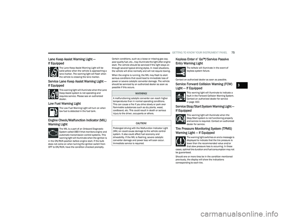
Lane Keep Assist Warning Light —
If Equipped
The Lane Keep Assist Warning Light will be
solid yellow when the vehicle is approaching a
lane marker. The warning light will flash when
the vehicle is crossing the lane marker.
Service Lane Keep Assist Warning Light —
If Equipped
This warning light will illuminate when the Lane
Keep Assist system is not operating and
requires service. Please see an authorized
dealer.
Low Fuel Warning Light
The Low Fuel Warning Light will turn on when
low fuel is detected in the fuel tank.
Engine Check/Malfunction Indicator (MIL)
Warning Light
The MIL is a part of an Onboard Diagnostic
System called OBD II that monitors engine and
automatic transmission control systems. This
warning light will illuminate when the ignition is
in the ON/RUN position before engine start. If the bulb
does not come on when turning the ignition switch from
OFF to ON/RUN, have the condition checked promptly. Certain conditions, such as a loose or missing gas cap,
poor quality fuel, etc., may illuminate the light after engine
start. The vehicle should be serviced if the light stays on
through several typical driving styles. In most situations,
the vehicle will drive normally and will not require towing.
When the engine is running, the MIL may flash to alert
serious conditions that could lead to immediate loss of
power or severe catalytic converter damage. The vehicle
should be serviced by an authorized dealer as soon as
possible if this occurs.
Keyless Enter n’ Go™/Service Passive
Entry Warning Light
The telltale will illuminate in the event of
keyless system failure.
Contact an authorized dealer as soon as possible.
Service Forward Collision Warning (FCW)
Light — If Equipped
This warning light will illuminate to indicate a
fault in the Forward Collision Warning System.
Contact an authorized dealer for service
Úpage 162.
Service Stop/Start System Warning Light —
If Equipped
This warning light will illuminate when the
Stop/Start system is not functioning properly
and service is required. Contact an authorized
dealer for service.
Tire Pressure Monitoring System (TPMS)
Warning Light — If Equipped
The warning light switches on and a message is
displayed to indicate that the tire pressure is
lower than the recommended value and/or
that slow pressure loss is occurring. In these
cases, optimal tire duration and fuel consumption may not
be guaranteed.
Should one or more tires be in the condition mentioned
previously, the display will show the indications
corresponding to each tire.
WARNING!
A malfunctioning catalytic converter can reach higher
temperatures than in normal operating conditions.
This can cause a fire if you drive slowly or park over
flammable substances such as dry plants, wood,
cardboard, etc. This could result in death or serious
injury to the driver, occupants or others.
CAUTION!
Prolonged driving with the Malfunction Indicator Light
(MIL) on could cause damage to the vehicle control
system. It also could affect fuel economy and
driveability. If the MIL is flashing, severe catalytic
converter damage and power loss will soon occur.
Immediate service is required.
3
23_GG_OM_EN_USC_t.book Page 75
Page 79 of 288
GETTING TO KNOW YOUR INSTRUMENT PANEL77
YELLOW INDICATOR LIGHTS
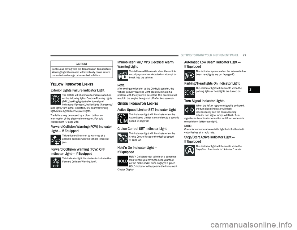
Exterior Lights Failure Indicator Light
The telltale will illuminate to indicate a failure
on the following lights: Daytime Running Lights
(DRL)/parking lights/trailer turn signal
indicators (if present)/trailer lights (if present)/
side lights/turn signal indicators/low beam/reversing
light/brake lights/license plate lights.
The failure may be caused by a blown bulb or an
interruption of the electrical connection. For bulb
replacement
Úpage 246.
Forward Collision Warning (FCW) Indicator
Light — If Equipped
This telltale will turn on to warn you of a
possible collision with the vehicle in front of
you.
Forward Collision Warning (FCW) OFF
Indicator Light — If Equipped
This indicator light illuminates to indicate that
Forward Collision Warning is off.
Immobilizer Fail / VPS Electrical Alarm
Warning Light
This telltale will illuminate when the vehicle
security system has detected an attempt to
break into the vehicle.
NOTE:After cycling the ignition to the ON/RUN position, the
Vehicle Security Warning Light could illuminate if a
problem with the system is detected. This condition will
result in the engine being shut off after two seconds.
GREEN INDICATOR LIGHTS
Active Speed Limiter SET Indicator Light
This indicator light will illuminate when the
Active Speed Limiter is on and set to a specific
speed
Úpage 90.
Cruise Control SET Indicator Light
This indicator light will illuminate when the
Cruise Control is set to the desired speed
Úpage 92.
Hold’n Go Indicator Light —
If Equipped
Hold’n Go keeps your vehicle at a complete
stop without you having to keep your foot
on the brake pedal. Once engaged a green
HOLD indicator will appear in the Instrument
Cluster Display.
Automatic Low Beam Indicator Light —
If Equipped
This indicator appears when the automatic low
beam headlights are on Úpage 40.
Parking/Headlights On Indicator Light
This indicator light will illuminate when the
parking lights or headlights are turned on.
Turn Signal Indicator Lights
When the left or right turn signal is activated,
the turn signal indicator will flash
independently and the corresponding
exterior turn signal lamps will flash. Turn
signals can be activated when the multifunction lever is
moved down (left) or up (right).
NOTE:Check for an inoperative outside light bulb if either indi -
cator flashes at a rapid rate.
Stop/Start Active Indicator Light —
If Equipped
This indicator light will illuminate when the
Stop/Start function is in “Autostop” mode.
CAUTION!
Continuous driving with the Transmission Temperature
Warning Light illuminated will eventually cause severe
transmission damage or transmission failure.
3
23_GG_OM_EN_USC_t.book Page 77
Page 80 of 288
78GETTING TO KNOW YOUR INSTRUMENT PANEL
WHITE INDICATOR LIGHTS
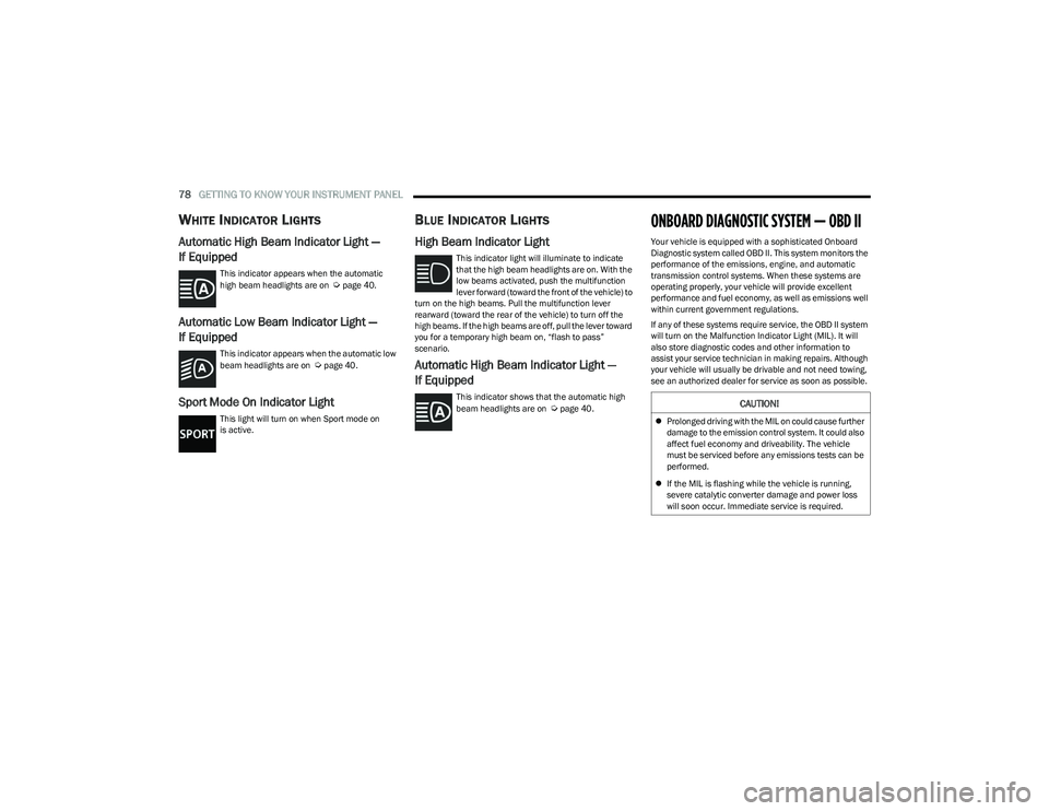
Automatic High Beam Indicator Light —
If Equipped
This indicator appears when the automatic
high beam headlights are on Úpage 40.
Automatic Low Beam Indicator Light —
If Equipped
This indicator appears when the automatic low
beam headlights are on Úpage 40.
Sport Mode On Indicator Light
This light will turn on when Sport mode on
is active.
BLUE INDICATOR LIGHTS
High Beam Indicator Light
This indicator light will illuminate to indicate
that the high beam headlights are on. With the
low beams activated, push the multifunction
lever forward (toward the front of the vehicle) to
turn on the high beams. Pull the multifunction lever
rearward (toward the rear of the vehicle) to turn off the
high beams. If the high beams are off, pull the lever toward
you for a temporary high beam on, “flash to pass”
scenario.
Automatic High Beam Indicator Light —
If Equipped
This indicator shows that the automatic high
beam headlights are on Úpage 40.
ONBOARD DIAGNOSTIC SYSTEM — OBD II
Your vehicle is equipped with a sophisticated Onboard
Diagnostic system called OBD II. This system monitors the
performance of the emissions, engine, and automatic
transmission control systems. When these systems are
operating properly, your vehicle will provide excellent
performance and fuel economy, as well as emissions well
within current government regulations.
If any of these systems require service, the OBD II system
will turn on the Malfunction Indicator Light (MIL). It will
also store diagnostic codes and other information to
assist your service technician in making repairs. Although
your vehicle will usually be drivable and not need towing,
see an authorized dealer for service as soon as possible.
CAUTION!
Prolonged driving with the MIL on could cause further
damage to the emission control system. It could also
affect fuel economy and driveability. The vehicle
must be serviced before any emissions tests can be
performed.
If the MIL is flashing while the vehicle is running,
severe catalytic converter damage and power loss
will soon occur. Immediate service is required.
23_GG_OM_EN_USC_t.book Page 78
Page 82 of 288
80
STARTING AND OPERATING
STARTING THE ENGINE
Before starting your vehicle, adjust your seat, adjust both
inside and outside mirrors, and fasten your seat belts.Start the engine with the gear selector in the NEUTRAL or
PARK position. Apply the brake before shifting to any
driving range.
NORMAL STARTING
Place the ignition switch in the START position and release
when the engine starts. If the engine fails to start within
10 seconds, place the ignition switch in the OFF position,
wait 10 to 15 seconds, then repeat the “Normal Starting”
procedure.
Tip Start Feature
Place the ignition switch in the START position and release
it as soon as the starter engages. The starter motor will
continue to run, and will automatically disengage itself
when the engine is running. If the engine fails to start,
place the ignition switch in the OFF position, wait 10 to
15 seconds, then repeat the “Normal Starting” procedure.
Automatic Transmission
The gear selector must be in the NEUTRAL or PARK
position before you can start the engine. Apply the brakes
before shifting into any driving gear.Keyless Enter ’n Go™ Functions — Using The ENGINE
START/STOP Button
1. The transmission must be in PARK or NEUTRAL.
2. Press and hold the brake pedal while pushing the
ENGINE START/STOP button once.
3. The system starts the vehicle. If the vehicle fails to start, the starter will disengage automatically after
10 seconds.
4. If you wish to stop the cranking of the engine prior to the engine starting, push the ENGINE START/STOP
button again.
WARNING!
When exiting the vehicle, always remove the key fob
from the vehicle and lock your vehicle.
Never leave children alone in a vehicle, or with
access to an unlocked vehicle.
Allowing children to be in a vehicle unattended is
dangerous for a number of reasons. A child or others
could be seriously or fatally injured. Children should
be warned not to touch the parking brake, brake
pedal or the transmission gear selector.
Do not leave the key fob in or near the vehicle, or in
a location accessible to children, and do not leave
the ignition of a vehicle equipped with Keyless
Enter ’n Go™ in the ON/RUN position. A child could
operate power windows, other controls, or move the
vehicle.
Do not leave children or animals inside parked
vehicles in hot weather. Interior heat buildup may
cause serious injury or death.
CAUTION!
Damage to the transmission may occur if the following
precautions are not observed:
Do not shift between PARK, REVERSE, NEUTRAL, or
DRIVE when the engine is above idle speed.
Shift into or out of PARK or REVERSE only after the
vehicle has come to a complete stop.
Before shifting into any gear, make sure your foot is
firmly on the brake pedal.
23_GG_OM_EN_USC_t.book Page 80
Page 84 of 288
82STARTING AND OPERATING
STOPPING THE ENGINE
Vehicles Equipped With Electronic Key
(Keyless Enter ’n Go™):
To shut off the engine with vehicle speed greater than
5 mph (8 km/h), you must push and hold the ignition or
push the ENGINE START/STOP button three times
consecutively within a few seconds. The engine will shut
down, and the ignition will be placed in the ON/RUN
position.
Turning off the car (placing the ignition from the ON/RUN
position to the OFF position), the power supply to the
accessories are maintained for a period of three minutes.
Opening the driver’s side door with the ignition in ON/RUN
will sound a short chime that reminds the driver to place
the ignition to OFF.
When the ignition is in the OFF position, the window
switches remain active for up to 10 minutes.
Opening a front door will cancel this function.
After severe driving, idle the engine to allow the
temperature inside the engine compartment to cool
before shutting off the engine.
ENGINE BREAK-IN RECOMMENDATIONS
A long break-in period is not required for the engine and
drivetrain (transmission and axle) in your vehicle.
Drive moderately during the first 300 miles (500 km).
After the initial 60 miles (100 km), speeds up to 50 or
55 mph (80 or 90 km/h) are desirable. While cruising, brief full-throttle acceleration within the
limits of local traffic laws contributes to a good break-in.
Wide-open throttle acceleration in low gear can be
detrimental and should be avoided.
The engine oil installed in the engine at the factory is a
high-quality energy conserving type lubricant. Oil changes
should be consistent with anticipated climate conditions
under which vehicle operations will occur. For the
recommended viscosity and quality grades
Úpage 269.
NOTE:A new engine may consume some oil during its first few
thousand miles (kilometers) of operation. This should be
considered a normal part of the break-in and not inter
-
preted as a problem.
PARK BRAKE
ELECTRIC PARK BRAKE (EPB)
Your vehicle is equipped with an EPB system that offers
simple operation, and some additional features that make
the parking brake more convenient and useful.
The parking brake is primarily intended to prevent the
vehicle from rolling while parked. Before leaving the
vehicle, make sure that the parking brake is applied.
Also, be certain to leave the transmission in PARK. You can engage the parking brake in two ways:
Manually, by applying the EPB switch.
Automatically, by enabling the Auto Park Brake feature
in the Customer Programmable Features section of the
Uconnect settings
Úpage 130.
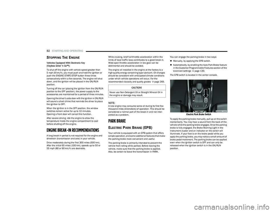
The EPB switch is located in the center console.
Electric Park Brake Switch
To apply the parking brake manually, pull up on the switch
momentarily. You may hear a sound from the back of the
vehicle while the parking brake engages. Once the parking
brake is fully engaged, the Brake Warning Light in the
instrument cluster and an indicator on the switch will
illuminate. If your foot is on the brake pedal while you
apply the parking brake, you may notice a small amount of
brake pedal movement. The parking brake can be applied
even when the ignition switch is OFF and can only be
released when the ignition switch is in the ON/RUN
position.
CAUTION!
Never use Non-Detergent Oil or Straight Mineral Oil in
the engine or damage may result.
23_GG_OM_EN_USC_t.book Page 82
Page 85 of 288
STARTING AND OPERATING83
(Continued)
NOTE:The EPB Warning Light will illuminate if the EPB switch is
held for longer than 60 seconds in either the released or
applied position. The light will extinguish upon releasing
the switch.
If the Auto Park Brake feature is enabled, the parking
brake will automatically engage whenever the
transmission is placed into PARK. If your foot is on the
brake pedal, you may notice a small amount of brake
pedal movement while the parking brake is engaging.
The parking brake will release automatically when the
ignition switch is ON/RUN, the transmission is in DRIVE or
REVERSE, the driver’s seat belt is buckled, and an attempt
is made to drive away.
To release the parking brake manually, the ignition switch
must be in the ON/RUN position. Put your foot on the
brake pedal, then push the EPB switch down momentarily.
You may hear a sound from the back of the car while the
parking brake disengages. You may also notice a small
amount of movement in the brake pedal. Once the parking
brake is fully disengaged, the Brake Warning Light in the
instrument cluster and the LED indicator on the switch will
extinguish.
NOTE:When parking on a hill, it is important to turn the front
wheels toward the curb on a downhill grade and away from
the curb on an uphill grade. Apply the parking brake before
placing the gear selector in PARK, otherwise the load on
the transmission locking mechanism may make it difficult to move the gear selector out of PARK. The parking brake
should always be applied whenever the driver is not in the
vehicle.
If exceptional circumstances should make it necessary to
engage the parking brake while the vehicle is in motion,
maintain upward pressure on the EPB switch for as long as
engagement is desired. The Brake Warning Light will
illuminate, and a continuous chime will sound. The rear
stop lamps will also be illuminated automatically while the
vehicle remains in motion.
To disengage the parking brake while the vehicle is in
motion, release the switch. If the vehicle is brought to a
complete stop using the parking brake, when the vehicle
reaches approximately 3 mph, (5 km/h) the parking brake
will remain engaged.
WARNING!
Do not rely on the parking brake to operate effec -
tively if the rear brakes have been immersed in water
or mud.
Never use the PARK position as a substitute for the
parking brake. Always apply the parking brake fully
when parked to guard against vehicle movement and
possible injury or damage.
When leaving the vehicle, always remove the key fob
from the ignition and lock your vehicle.
Never leave children alone in a vehicle, or with
access to an unlocked vehicle. Allowing children to
be in a vehicle unattended is dangerous for a
number of reasons. A child or others could be seri -
ously or fatally injured. Children should be warned
not to touch the parking brake, brake pedal or the
gear selector.
Do not leave the key fob in or near the vehicle, or in
a location accessible to children, and do not leave
the ignition of a vehicle equipped with Keyless
Enter ’n Go™ in the ACC or ON/RUN position. A child
could operate power windows, other controls, or
move the vehicle.
Be sure the parking brake is fully disengaged before
driving; failure to do so can lead to brake failure and
a collision.
Always fully apply the parking brake when leaving
your vehicle, or it may roll and cause damage or
injury. Also be certain to leave the transmission in
PARK. Failure to do so may allow the vehicle to roll
and cause damage or injury.
CAUTION!
If the Brake System Warning Light remains on with the
parking brake released, a brake system malfunction is
indicated. Have the brake system serviced by an
authorized dealer immediately.
WARNING!
4
23_GG_OM_EN_USC_t.book Page 83