check engine DODGE HORNET 2023 Owners Manual
[x] Cancel search | Manufacturer: DODGE, Model Year: 2023, Model line: HORNET, Model: DODGE HORNET 2023Pages: 288, PDF Size: 14.2 MB
Page 7 of 288
5
TRAILER TOWING............................................................. 121Common Towing Definitions .................................... 121
Trailer Towing Weights
(Maximum Trailer Weight Ratings) .......................... 122Trailer And Tongue Weight ....................................... 123
Towing Requirements .............................................. 123
Towing Tips ............................................................... 125
RECREATIONAL TOWING (BEHIND MOTORHOME) .... 126 Towing This Vehicle Behind Another Vehicle .......... 126
Recreational Towing ................................................. 127
DRIVING TIPS ................................................................... 127 Driving On Slippery Surfaces.................................... 127
Driving Through Water ............................................. 128
MULTIMEDIA
UCONNECT SYSTEMS ..................................................... 129
CYBERSECURITY ............................................................. 129
UCONNECT SETTINGS ..................................................... 130Customer Programmable Features ......................... 130
STEERING WHEEL AUDIO CONTROLS —
IF EQUIPPED .................................................................... 150 Steering Wheel Rotary Control ................................. 150Controls on Central Tunnel....................................... 151
MY CAR ............................................................................. 151
PERFORMANCE PAGES .................................................. 152 Technical Gauges...................................................... 152Consumption History ................................................ 152Accessory Gauges ..................................................... 153
RADIO OPERATION AND MOBILE PHONES .................. 153 Regulatory And Safety Information .......................... 153
SAFETY
SAFETY FEATURES .......................................................... 154Anti-Lock Brake System (ABS) ................................ 154
Electronic Brake Control (EBC) System .................. 155
AUXILIARY DRIVING SYSTEMS ...................................... 159 Blind Spot Monitoring (BSM) —
If Equipped ................................................................ 159Forward Collision Warning (FCW)
With Mitigation — If Equipped .................................. 162
Tire Pressure Monitoring System (TPMS) ............... 165
OCCUPANT RESTRAINT SYSTEMS ............................... 168 Occupant Restraint Systems Features ................... 168
Important Safety Precautions .................................. 168
Seat Belt Systems .................................................... 169
Supplemental Restraint Systems (SRS).................. 175
Child Restraints ........................................................ 188
SAFETY TIPS .................................................................... 199 Transporting Passengers ......................................... 199
Transporting Pets .................................................... 199
Connected Vehicles .................................................. 199Safety Checks You Should Make Inside
The Vehicle ............................................................... 200Periodic Safety Checks You Should Make Outside
The Vehicle ................................................................ 201Exhaust Gas .............................................................. 202
Carbon Monoxide Warnings ..................................... 202
IN CASE OF EMERGENCY
HAZARD WARNING FLASHERS ......................................203
SOS SYSTEM — IF EQUIPPED.......................................... 203
JACKING AND TIRE CHANGING —
IF EQUIPPED
b
...............................................................206
Preparations For Jacking ......................................... 206
Jack And Tools Location/Spare Tire Stowage —
If Equipped................................................................. 207
Jacking Instructions ................................................. 208
TIRE INFLATOR KIT — IF EQUIPPED
b
........................211
Description................................................................. 211
Inflation Procedure.................................................... 212
Checking And Restoring Tire Pressure..................... 214
Sealant Cartridge Replacement ............................... 214
JUMP STARTING ...............................................................215 Preparations For Jump Start..................................... 215
Jump Starting Procedure .......................................... 216
REFUELING IN EMERGENCY ........................................... 217
IF YOUR ENGINE OVERHEATS ........................................218
GEAR SELECTOR OVERRIDE .......................................... 218
FREEING A STUCK VEHICLE ........................................... 219
TOWING A DISABLED VEHICLE.......................................220 Without The Key Fob ................................................. 221
All-Wheel Drive (AWD) Models ................................. 221
Tow Eye — If Equipped .............................................. 221
ENHANCED ACCIDENT RESPONSE
SYSTEM (EARS) ...............................................................222
EVENT DATA RECORDER (EDR)......................................222
23_GG_OM_EN_USC_t.book Page 5
Page 8 of 288
6
SERVICING AND MAINTENANCE
SCHEDULED SERVICING ................................................ 223
Maintenance Plan ..................................................... 224
ENGINE COMPARTMENT................................................. 226 2.0L Engine .............................................................. 226Checking Oil Level ..................................................... 227
Adding Washer Fluid ................................................ 227Maintenance-Free Battery........................................ 227Pressure Washing ..................................................... 228
VEHICLE MAINTENANCE ................................................. 228 Engine Oil................................................................... 228
Engine Oil Filter ......................................................... 228
Engine Air Cleaner Filter ........................................... 229
Air Conditioner Maintenance ................................... 229
Body Lubrication ....................................................... 230Wiper Blades ............................................................ 230
Exhaust System ........................................................ 232
Cooling System.......................................................... 233
Brake System ........................................................... 236
Automatic Transmission —
If Equipped ................................................................ 236
Fuses ......................................................................... 237
Bulb Replacement ................................................... 246
TIRES ................................................................................ 246 Tire Safety Information ............................................ 246
Tires — General Information .................................... 254
Tire Types................................................................... 257
Spare Tires — If Equipped ........................................ 258Snow Traction Devices ............................................ 259
Tire Rotation Recommendations ............................ 260 DEPARTMENT OF TRANSPORTATION UNIFORM
TIRE QUALITY GRADES .................................................. 260
Treadwear ................................................................. 260Traction Grades ........................................................ 261Temperature Grades ................................................ 261
STORING THE VEHICLE ................................................... 261
BODYWORK ...................................................................... 262 Protection From Atmospheric Agents ...................... 262Body And Underbody Maintenance ......................... 262
Preserving The Bodywork ......................................... 263
INTERIORS ....................................................................... 263 Seats And Fabric Parts ............................................. 263
Plastic And Coated Parts .......................................... 264Leather Surfaces ...................................................... 264
Glass Surfaces ......................................................... 264
TECHNICAL SPECIFICATIONS
VEHICLE IDENTIFICATION NUMBER (VIN)..................... 265
BRAKE SYSTEM .............................................................. 265
WHEEL AND TIRE TORQUE SPECIFICATIONS .............. 265 Torque Specifications ............................................... 265
FUEL REQUIREMENTS ..................................................... 266 2.0L Engine ............................................................... 266Reformulated Gasoline ........................................... 266Gasoline/Oxygenate Blends ................................... 266E-85 Usage In Non-Flex Fuel Vehicles ..................... 267CNG And LP Fuel System Modifications.................. 267
Methylcyclopentadienyl Manganese
Tricarbonyl (MMT) In Gasoline ................................. 267
Materials Added To Fuel .......................................... 267Fuel System Cautions ............................................... 267 FLUID CAPACITIES ...........................................................268
ENGINE FLUIDS AND LUBRICANTS ................................269
CHASSIS FLUIDS AND LUBRICANTS ..............................269
CUSTOMER ASSISTANCE
SUGGESTIONS FOR OBTAINING SERVICE FOR
YOUR VEHICLE ................................................................. 270 Prepare For The Appointment .................................. 270
Prepare A List ............................................................ 270Be Reasonable With Requests ................................. 270
IF YOU NEED ASSISTANCE .............................................270 Roadside Assistance ................................................. 271
FCA US LLC Customer Center ................................... 272
FCA Canada Inc. Customer Care .............................. 272
Mexico ........................................................................ 272
Puerto Rico And US Virgin Islands............................ 272
Customer Assistance For The Hearing Or
Speech Impaired (TDD/TTY) ..................................... 272
Service Contract ....................................................... 272
WARRANTY INFORMATION.............................................273
MOPAR® PARTS ..............................................................273
REPORTING SAFETY DEFECTS ......................................273 In The 50 United States And Washington, D.C........ 273
In Canada................................................................... 273
PUBLICATION ORDER FORMS .......................................274
CHANGE OF OWNERSHIP OR ADDRESS.......................274
GENERAL INFORMATION................................................. 275
23_GG_OM_EN_USC_t.book Page 6
Page 12 of 288
10
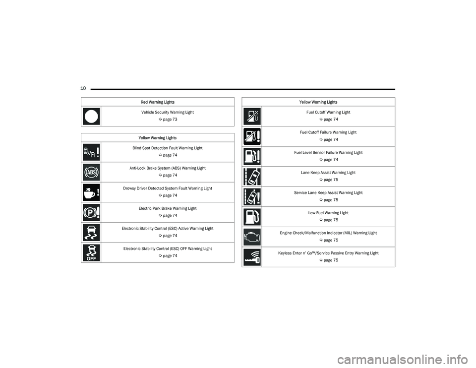
Vehicle Security Warning Light
Úpage 73
Yellow Warning Lights
Blind Spot Detection Fault Warning Light
Úpage 74
Anti-Lock Brake System (ABS) Warning Light
Úpage 74
Drowsy Driver Detected System Fault Warning Light
Úpage 74
Electric Park Brake Warning Light
Úpage 74
Electronic Stability Control (ESC) Active Warning Light
Úpage 74
Electronic Stability Control (ESC) OFF Warning Light
Úpage 74
Red Warning Lights
Fuel Cutoff Warning Light
Úpage 74
Fuel Cutoff Failure Warning Light
Úpage 74
Fuel Level Sensor Failure Warning Light
Úpage 74
Lane Keep Assist Warning Light
Úpage 75
Service Lane Keep Assist Warning Light
Úpage 75
Low Fuel Warning Light
Úpage 75
Engine Check/Malfunction Indicator (MIL) Warning Light
Úpage 75
Keyless Enter n’ Go™/Service Passive Entry Warning Light
Úpage 75
Yellow Warning Lights
23_GG_OM_EN_USC_t.book Page 10
Page 18 of 288
16GETTING TO KNOW YOUR VEHICLE
SENTRY KEY
The Sentry Key Immobilizer system prevents unauthorized
vehicle operation by disabling the engine. The system
does not need to be armed or activated. Operation is
automatic, regardless of whether the vehicle is locked or
unlocked.
The system uses a key fob, keyless push button ignition
and a Radio Frequency (RF) receiver to prevent
unauthorized vehicle operation. Therefore, only key fobs
that are programmed to the vehicle can be used to start
and operate the vehicle. The system cannot reprogram a
key fob obtained from another vehicle.
After placing the ignition in the ON/RUN position, the
Vehicle Security Light will turn on for three seconds for a
bulb check. If the light remains on after the bulb check, it
indicates that there is a problem with the electronics. In
addition, if the light begins to flash after the bulb check, it
indicates that someone attempted to start the engine with
an invalid key fob. In the event that a valid key fob is used
to start the engine but there is an issue with the vehicle
electronics, the engine will start and shut off after two
seconds.
If the Vehicle Security Light turns on during normal vehicle
operation (vehicle running for longer than 10 seconds), it
indicates that there is a fault in the electronics. Should
this occur, have the vehicle serviced as soon as possible
by an authorized dealer. All of the key fobs provided with your new vehicle have
been programmed to the vehicle electronics
Úpage 275.
NOTE:A key fob that has not been programmed is also
considered an invalid key.
IGNITION SWITCH
KEYLESS ENTER ‘N GO™ IGNITION
This feature allows the driver to operate the ignition with
the push of a button as long as the key fob is in the
passenger compartment.
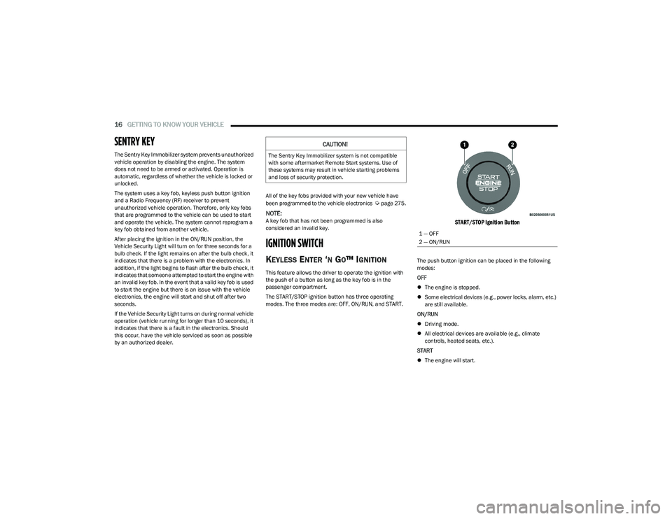
The START/STOP ignition button has three operating
modes. The three modes are: OFF, ON/RUN, and START.
START/STOP Ignition Button
The push button ignition can be placed in the following
modes:
OFF
The engine is stopped.
Some electrical devices (e.g., power locks, alarm, etc.)
are still available.
ON/RUN
Driving mode.
All electrical devices are available (e.g., climate
controls, heated seats, etc.).
START
The engine will start.
CAUTION!
The Sentry Key Immobilizer system is not compatible
with some aftermarket Remote Start systems. Use of
these systems may result in vehicle starting problems
and loss of security protection.
1 — OFF
2 — ON/RUN
23_GG_OM_EN_USC_t.book Page 16
Page 22 of 288
20GETTING TO KNOW YOUR VEHICLE
REMOTE START ABORT MESSAGE —
I
F EQUIPPED
One of the following messages will display in the
instrument cluster display if the vehicle fails to remote
start or exits Remote Start prematurely:
Remote Start Aborted — Door Open
Remote Start Aborted — Hood Open
Remote Start Aborted — Fuel Low
Remote Start Aborted — Liftgate Open
Remote Start Aborted — Too Cold
Remote Start Aborted — Time Expired
Remote Start Disabled — Start Vehicle To Reset
The message will stay active until the ignition is placed in
the ON/RUN position.
VEHICLE SECURITY SYSTEM — IF EQUIPPED
The Vehicle Security system monitors the vehicle doors,
hood, liftgate, and the Keyless Enter ‘n Go™ Ignition for
unauthorized operation. It also monitors movement inside
the passenger compartment (volumetric protection —
if equipped), cutting of battery cables, and unexpected
lifting/tilting of the vehicle (anti-lift protection —
if equipped). If something triggers the system, the Vehicle Security
system will provide the following audible and visible
signals:
The horn will pulse
The turn signals will flash
NOTE:
The Vehicle Security system is activated by the Engine
Immobilizer system, which is automatically activated
when you get out of the vehicle with the key fob and
lock the doors.
The Vehicle Security system is factory adjusted to stan -
dards from different countries.
The Vehicle Security system is a complementary secu -
rity system developed to hinder the occurrence of
vehicle theft and prevent vandalism. It does not
prevent the theft of your vehicle; the system is a deter -
rent.
TO ARM THE SYSTEM
Follow these steps to arm the Vehicle Security system:
1. Make sure the vehicle’s ignition is placed in the OFF position.
For vehicles equipped with Keyless Entry, make
sure the vehicle’s keyless ignition system is OFF. 2. Perform one of the following methods to lock the
vehicle:
Push the lock button on the interior power door
lock switch with the driver and/or passenger door
open.
Push the lock button on the exterior Passive Entry
door handle with a valid key fob available in the
same exterior zone
Úpage 23.
Push the lock button on the key fob.
3. If any doors (or liftgate) are open, close them.
When the Vehicle Security system is armed (except on
some versions for specific markets), the system will emit
an acoustic warning and a warning light (located next to
the interior door handle) will flash until it is disarmed.
NOTE:
If there is a fault with the system, the system will emit
an acoustic signal a second time.
If this occurs, wait about 4 seconds and switch off the
Vehicle Security system following this procedure:
a. Press the unlock button on the key fob.
b. Check that the doors, hood, and liftgate are closed, and then reactivate the system by pressing
the lock button.
If the alarm emits a sound even when the doors, hood,
and liftgate are closed, there is a fault with the system.
Contact an authorized dealer for assistance.
The vehicle doors can be locked without arming the
Vehicle Security system by using the emergency key in
the exterior door lock cylinder.
23_GG_OM_EN_USC_t.book Page 20
Page 28 of 288
26GETTING TO KNOW YOUR VEHICLE
NOTE:
When the Child-Protection Door Lock system is
engaged, the door can be opened only by using the
outside door handle even though the inside door lock
is in the unlocked position.
After disengaging the Child-Protection Door Lock
system, always test the door from the inside to make
certain it is in the desired position.
After engaging the Child-Protection Door Lock system,
always test the door from the inside to make certain it
is in the desired position.
For emergency exit with the system engaged, rotate the
door lock button until the lock indicator is hidden
(unlocked position), lower the window, and open the
door with the outside door handle.
NOTE:Always use this device when carrying children. After
engaging the child lock on both rear doors, check for
effective engagement by trying to open a door with the
internal handle. Once the Child-Protection Door Lock
system is engaged, it is impossible to open the doors from
inside the vehicle. Before getting out of the vehicle, be
sure to check that there is no one left inside.
STEERING WHEEL
TILT/TELESCOPING STEERING COLUMN
This feature allows you to tilt the steering column upward
or downward. It also allows you to lengthen or shorten the
steering column. The tilt/telescoping lever is located
below the steering wheel at the end of the steering
column.
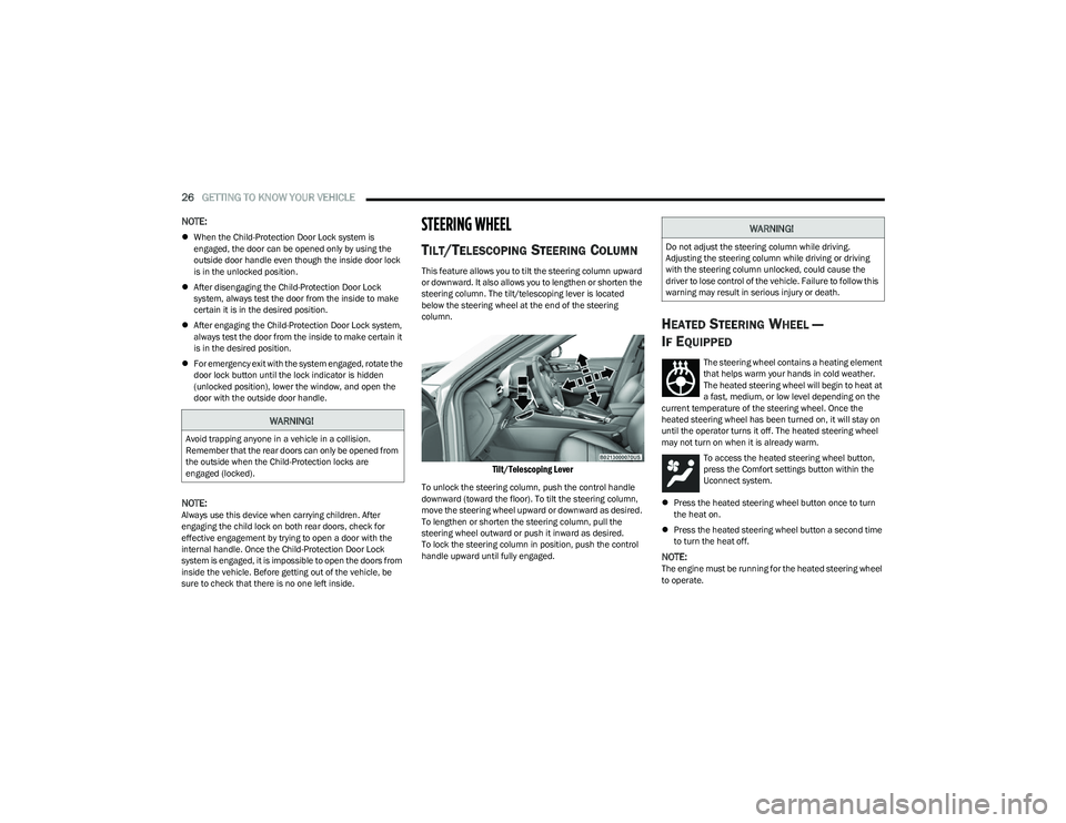
Tilt/Telescoping Lever
To unlock the steering column, push the control handle
downward (toward the floor). To tilt the steering column,
move the steering wheel upward or downward as desired.
To lengthen or shorten the steering column, pull the
steering wheel outward or push it inward as desired.
To lock the steering column in position, push the control
handle upward until fully engaged.
HEATED STEERING WHEEL —
I
F EQUIPPED
The steering wheel contains a heating element
that helps warm your hands in cold weather.
The heated steering wheel will begin to heat at
a fast, medium, or low level depending on the
current temperature of the steering wheel. Once the
heated steering wheel has been turned on, it will stay on
until the operator turns it off. The heated steering wheel
may not turn on when it is already warm.
To access the heated steering wheel button,
press the Comfort settings button within the
Uconnect system.
Press the heated steering wheel button once to turn
the heat on.
Press the heated steering wheel button a second time
to turn the heat off.
NOTE:The engine must be running for the heated steering wheel
to operate.
WARNING!
Avoid trapping anyone in a vehicle in a collision.
Remember that the rear doors can only be opened from
the outside when the Child-Protection locks are
engaged (locked).
WARNING!
Do not adjust the steering column while driving.
Adjusting the steering column while driving or driving
with the steering column unlocked, could cause the
driver to lose control of the vehicle. Failure to follow this
warning may result in serious injury or death.
23_GG_OM_EN_USC_t.book Page 26
Page 68 of 288
66GETTING TO KNOW YOUR INSTRUMENT PANEL
INSTRUMENT CLUSTER DESCRIPTIONS
Use this QR code to access your digital
experience.
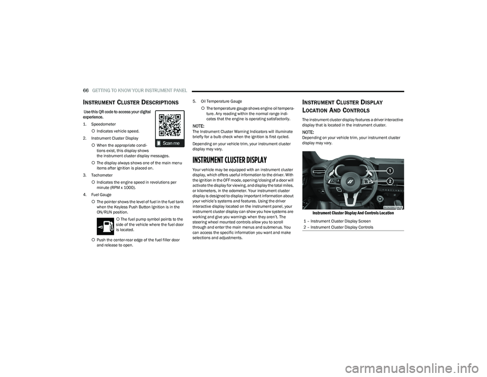
1. Speedometer
Indicates vehicle speed.
2. Instrument Cluster Display When the appropriate condi -
tions exist, this display shows
the instrument cluster display messages.
The display always shows one of the main menu
items after ignition is placed on.
3. Tachometer Indicates the engine speed in revolutions per
minute (RPM x 1000).
4. Fuel Gauge The pointer shows the level of fuel in the fuel tank
when the Keyless Push Button Ignition is in the
ON/RUN position.
The fuel pump symbol points to the
side of the vehicle where the fuel door
is located.
Push the center-rear edge of the fuel filler door
and release to open. 5. Oil Temperature Gauge
The temperature gauge shows engine oil tempera -
ture. Any reading within the normal range indi -
cates that the engine is operating satisfactorily.
NOTE:The Instrument Cluster Warning Indicators will illuminate
briefly for a bulb check when the ignition is first cycled.
Depending on your vehicle trim, your instrument cluster
display may vary.
INSTRUMENT CLUSTER DISPLAY
Your vehicle may be equipped with an instrument cluster
display, which offers useful information to the driver. With
the ignition in the OFF mode, opening/closing of a door will
activate the display for viewing, and display the total miles,
or kilometers, in the odometer. Your instrument cluster
display is designed to display important information about
your vehicle’s systems and features. Using the driver
interactive display located on the instrument panel, your
instrument cluster display can show you how systems are
working and give you warnings when they aren’t. The
steering wheel mounted controls allow you to scroll
through and enter the main menus and submenus. You
can access the specific information you want and make
selections and adjustments.
INSTRUMENT CLUSTER DISPLAY
L
OCATION AND CONTROLS
The instrument cluster display features a driver interactive
display that is located in the instrument cluster.
NOTE:Depending on your vehicle trim, your instrument cluster
display may vary.
Instrument Cluster Display And Controls Location
1 – Instrument Cluster Display Screen
2 – Instrument Cluster Display Controls
23_GG_OM_EN_USC_t.book Page 66
Page 73 of 288
GETTING TO KNOW YOUR INSTRUMENT PANEL71
The battery was recently replaced and was not charged
completely.
The battery was discharged by an electrical load left on
when the vehicle was parked.
The battery was used for an extended period with the
engine not running to supply radio, lights, chargers,
+12 Volts portable appliances like vacuum cleaners,
game consoles and similar devices.
What to do when an electrical load reduction action
message is present (“Battery Saver On” or
“Battery Saver Mode”)
During a trip:
Reduce power to unnecessary loads if possible:
Turn off redundant lights (interior or exterior)
Check what may be plugged into power outlets
+12 Volts, 150W, USB ports
Check HVAC settings (blower, temperature)
Check the audio settings (volume)
After a trip:
Check if any aftermarket equipment was installed
(additional lights, upfitter electrical accessories,
audio systems, alarms) and review specifications if any
(load and Ignition Off Draw currents).
Evaluate the latest driving cycles (distance, driving
time and parking time).
The vehicle should have service performed if the
message is still present during consecutive trips and
the evaluation of the vehicle and driving pattern did not
help to identify the cause.WARNING LIGHTS AND MESSAGES
The warning/indicator lights will illuminate in the
instrument panel together with a dedicated message and/
or acoustic signal when applicable. These indications are
indicative and precautionary and as such must not be
considered as exhaustive and/or alternative to the
information contained in the Owner’s Manual, which you
are advised to read carefully in all cases. Always refer to
the information in this chapter in the event of a failure
indication. All active telltales will display first if applicable.
The system check menu may appear different based upon
equipment options and current vehicle status. Some
telltales are optional and may not appear.
RED WARNING LIGHTS
Air Bag Warning Light
This warning light will illuminate to indicate a
fault with the air bag, and will turn on for four to
eight seconds as a bulb check when the
ignition is placed in the ON/RUN position. This
light will illuminate with a single chime when a fault with
the air bag has been detected, it will stay on until the fault
is cleared. If the light is either not on during startup, stays
on, or turns on while driving, have the system inspected at
an authorized dealer as soon as possible.
Brake Warning Light
This warning light monitors various brake
functions, including brake fluid level and
parking brake application. If the brake light
turns on it may indicate that the parking brake
is applied, that the brake fluid level is low, or that there is
a problem with the Anti-Lock Brake System reservoir. If the light remains on when the parking brake has been
disengaged, and the fluid level is at the full mark on the
master cylinder reservoir, it indicates a possible brake
hydraulic system malfunction or that a problem with the
Brake Booster has been detected by the Anti-Lock Brake
System (ABS) / Electronic Stability Control (ESC) system.
In this case, the light will remain on until the condition has
been corrected. If the problem is related to the brake
booster, the ABS pump will run when applying the brake,
and a brake pedal pulsation may be felt during each stop.
The dual brake system provides a reserve braking capacity
in the event of a failure to a portion of the hydraulic
system. A leak in either half of the dual brake system is
indicated by the Brake Warning Light, which will turn on
when the brake fluid level in the master cylinder has
dropped below a specified level.
The light will remain on until the cause is corrected.
NOTE:The light may flash momentarily during sharp cornering
maneuvers, which change fluid level conditions. The
vehicle should have service performed, and the brake
fluid level checked.
If brake failure is indicated, immediate repair is necessary.
WARNING!
Driving a vehicle with the red brake light on is
dangerous. Part of the brake system may have failed.
It will take longer to stop the vehicle. You could have a
collision. Have the vehicle checked immediately.
3
23_GG_OM_EN_USC_t.book Page 71
Page 74 of 288
72GETTING TO KNOW YOUR INSTRUMENT PANEL
Vehicles equipped with the Anti-Lock Brake System (ABS)
are also equipped with Electronic Brake Force Distribution
(EBD). In the event of an EBD failure, the Brake Warning
Light will turn on along with the ABS Light. Immediate
repair to the ABS system is required.
Operation of the Brake Warning Light can be checked by
turning the ignition switch from the OFF position to the
ON/RUN position. The light should illuminate for
approximately two seconds. The light should then turn off
unless the parking brake is applied or a brake fault is
detected. If the light does not illuminate, have the light
inspected by an authorized dealer.
The light also will turn on when the parking brake is
applied with the ignition switch in the ON/RUN position.
NOTE:This light shows only that the parking brake is applied.
It does not show the degree of brake application.
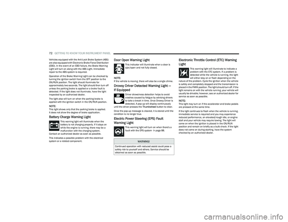
Battery Charge Warning Light
This warning light will illuminate when the
battery is not charging properly. If it stays on
while the engine is running, there may be a
malfunction with the charging system.
Contact an authorized dealer as soon as possible.
This indicates a possible problem with the electrical
system or a related component.
Door Open Warning Light
This indicator will illuminate when a door is
ajar/open and not fully closed.
NOTE:If the vehicle is moving, there will also be a single chime.
Drowsy Driver Detected Warning Light —
If Equipped
Driver drowsiness detection helps to avoid
crashes caused by fatigue by advising drivers
to take a break in time. Once Drowsy Driver is
detected, A pop-up will display continuously
until the driver presses the Thumbwheel button to clear.
Once the pop-up message is cleared, it is stored until the
condition is no longer true.
Electric Power Steering (EPS) Fault
Warning Light
This warning light will turn on when there's a
fault with the EPS system Úpage 88.
Electronic Throttle Control (ETC) Warning
Light
This warning light will illuminate to indicate a
problem with the ETC system. If a problem is
detected while the vehicle is running, the light
will either stay on or flash depending on the
nature of the problem. Cycle the ignition when the vehicle
is safely and completely stopped and the transmission is
placed in the PARK position. The light should turn off. If the
light remains on with the vehicle running, your vehicle will
usually be drivable; however, see an authorized dealer for
service as soon as possible.
NOTE:This light may turn on if the accelerator and brake pedals
are pressed at the same time.
If the light continues to flash when the vehicle is running,
immediate service is required and you may experience
reduced performance, an elevated/rough idle, or engine
stall and your vehicle may require towing. The light will
come on when the ignition is placed in the ON/RUN
position and remain on briefly as a bulb check. If the light
does not come on during starting, have the system
checked by an authorized dealer.
WARNING!
Continued operation with reduced assist could pose a
safety risk to yourself and others. Service should be
obtained as soon as possible.
23_GG_OM_EN_USC_t.book Page 72
Page 75 of 288
GETTING TO KNOW YOUR INSTRUMENT PANEL73
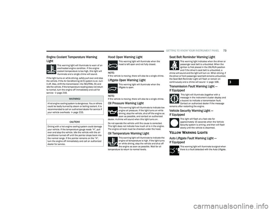
Engine Coolant Temperature Warning
Light
This warning light will illuminate to warn of an
overheated engine condition. If the engine
coolant temperature is too high, this light will
illuminate and a single chime will sound.
If the light turns on while driving, safely pull over and stop
the vehicle. If the Air Conditioning (A/C) system is on, turn
it off. Also, shift the transmission into NEUTRAL (N) and
idle the vehicle. If the temperature reading does not return
to normal, turn the engine off immediately and call for
service
Úpage 218.
Hood Open Warning Light
This warning light will illuminate when the
hood is left open and not fully closed.
NOTE:If the vehicle is moving, there will also be a single chime.
Liftgate Open Warning Light
This warning light will illuminate when the
liftgate is open.
NOTE:If the vehicle is moving, there will also be a single chime.
Oil Pressure Warning Light
This warning light will illuminate to indicate low
engine oil pressure. If the light turns on while
driving, stop the vehicle, shut off the engine as
soon as possible, and contact an authorized
dealer. A chime will sound when this light turns on.
Do not operate the vehicle until the cause is corrected.
This light does not indicate how much oil is in the engine.
The engine oil level must be checked under the hood.
Oil Temperature Warning Light
This warning light will illuminate to indicate the
engine oil temperature is high. If the light turns
on while driving, stop the vehicle and shut off
the engine as soon as possible. Wait for oil
temperature to return to normal levels.
Seat Belt Reminder Warning Light
This warning light indicates when the driver or
passenger seat belt is unbuckled. When the
ignition is first placed in the ON/RUN position
and if the driver’s seat belt is unbuckled, a
chime will sound and the light will turn on. When driving, if
the driver or front passenger seat belt remains unbuckled,
the Seat Belt Reminder Light will flash or remain on
continuously and a chime will sound
Úpage 168.
Transmission Fault Warning Light —
If Equipped
This light will illuminate (together with a
message in the instrument cluster display and
a buzzer) to indicate a transmission fault.
Contact an authorized dealer if the message
remains after restarting the engine.
Vehicle Security Warning Light —
If Equipped
This light will flash at a fast rate for
approximately 15 seconds when the Vehicle
Security system is arming, and then will flash
slowly until the vehicle is disarmed.
YELLOW WARNING LIGHTS
Auto Liftgate Fault Warning Light —
If Equipped
This warning light will illuminate to signal when
there is a fault detected with the Auto Liftgate.
WARNING!
A hot engine cooling system is dangerous. You or others
could be badly burned by steam or boiling coolant. It is
recommended to call an authorized dealer for service if
your vehicle overheats
Úpage 233.
CAUTION!
Driving with a hot engine cooling system could damage
your vehicle. If the temperature gauge reads “H”, pull
over and stop the vehicle. Idle the vehicle with the air
conditioner turned off until the pointer drops back into
the normal range. If the pointer remains on the “H”,
turn the engine off immediately and call an authorized
dealer for service.
3
23_GG_OM_EN_USC_t.book Page 73