clock DODGE HORNET 2023 Owners Manual
[x] Cancel search | Manufacturer: DODGE, Model Year: 2023, Model line: HORNET, Model: DODGE HORNET 2023Pages: 288, PDF Size: 14.2 MB
Page 24 of 288
22GETTING TO KNOW YOUR VEHICLE
(Continued)
DOORS
MANUAL DOOR LOCKS
The front doors can be manually unlocked by pulling the
inside door handle. The driver’s door can also be manually
locked/unlocked by inserting the emergency key into the
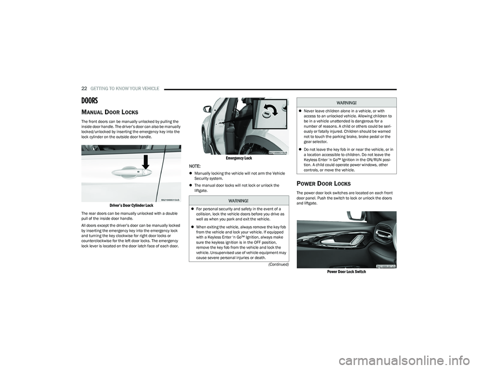
lock cylinder on the outside door handle.
Driver’s Door Cylinder Lock
The rear doors can be manually unlocked with a double
pull of the inside door handle.
All doors except the driver’s door can be manually locked
by inserting the emergency key into the emergency lock
and turning the key clockwise for right door locks or
counterclockwise for the left door locks. The emergency
lock lever is located on the door latch face of each door.
Emergency Lock
NOTE:
Manually locking the vehicle will not arm the Vehicle
Security system.
The manual door locks will not lock or unlock the
liftgate.
POWER DOOR LOCKS
The power door lock switches are located on each front
door panel. Push the switch to lock or unlock the doors
and liftgate.
Power Door Lock Switch
WARNING!
For personal security and safety in the event of a
collision, lock the vehicle doors before you drive as
well as when you park and exit the vehicle.
When exiting the vehicle, always remove the key fob
from the vehicle and lock your vehicle. If equipped
with a Keyless Enter ‘n Go™ Ignition, always make
sure the keyless ignition is in the OFF position,
remove the key fob from the vehicle and lock the
vehicle. Unsupervised use of vehicle equipment may
cause severe personal injuries or death.
Never leave children alone in a vehicle, or with
access to an unlocked vehicle. Allowing children to
be in a vehicle unattended is dangerous for a
number of reasons. A child or others could be seri -
ously or fatally injured. Children should be warned
not to touch the parking brake, brake pedal or the
gear selector.
Do not leave the key fob in or near the vehicle, or in
a location accessible to children. Do not leave the
Keyless Enter ‘n Go™ Ignition in the ON/RUN posi -
tion. A child could operate power windows, other
controls, or move the vehicle.
WARNING!
23_GG_OM_EN_USC_t.book Page 22
Page 42 of 288
40GETTING TO KNOW YOUR VEHICLE
EXTERIOR LIGHTS
MULTIFUNCTION LEVER
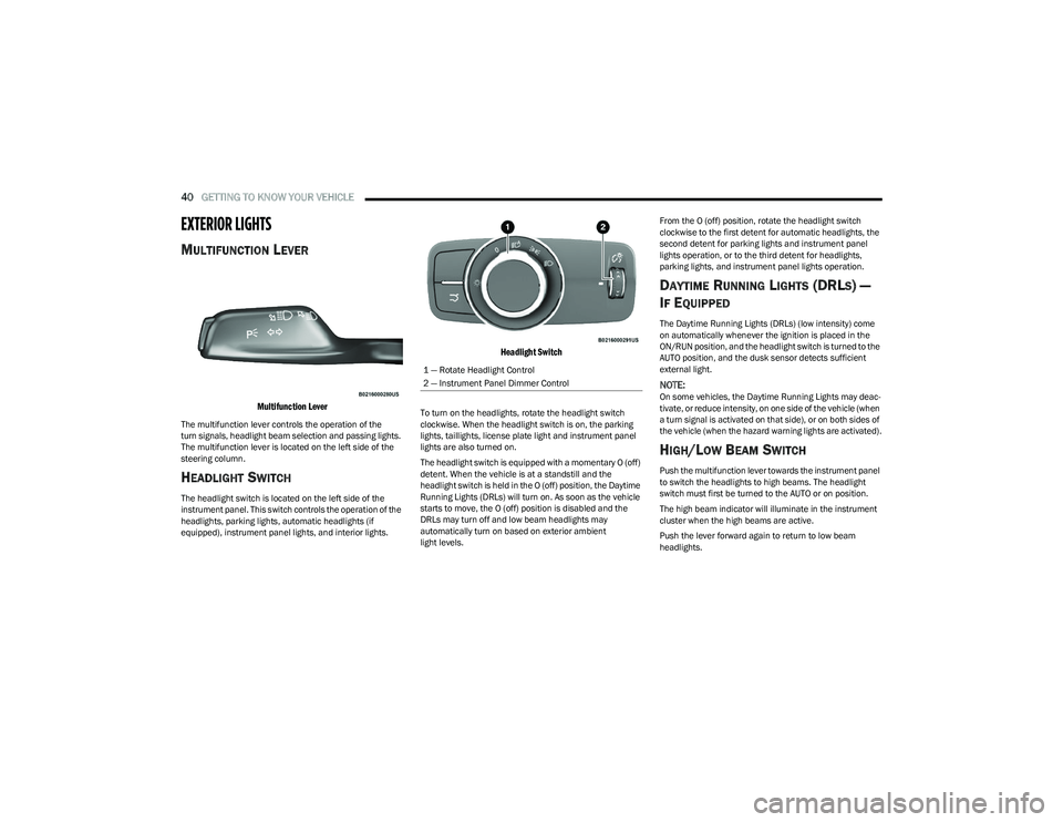
Multifunction Lever
The multifunction lever controls the operation of the
turn signals, headlight beam selection and passing lights.
The multifunction lever is located on the left side of the
steering column.
HEADLIGHT SWITCH
The headlight switch is located on the left side of the
instrument panel. This switch controls the operation of the
headlights, parking lights, automatic headlights (if
equipped), instrument panel lights, and interior lights.
Headlight Switch
To turn on the headlights, rotate the headlight switch
clockwise. When the headlight switch is on, the parking
lights, taillights, license plate light and instrument panel
lights are also turned on.
The headlight switch is equipped with a momentary O (off)
detent. When the vehicle is at a standstill and the
headlight switch is held in the O (off) position, the Daytime
Running Lights (DRLs) will turn on. As soon as the vehicle
starts to move, the O (off) position is disabled and the
DRLs may turn off and low beam headlights may
automatically turn on based on exterior ambient
light levels. From the O (off) position, rotate the headlight switch
clockwise to the first detent for automatic headlights, the
second detent for parking lights and instrument panel
lights operation, or to the third detent for headlights,
parking lights, and instrument panel lights operation.
DAYTIME RUNNING LIGHTS (DRLS) —
I
F EQUIPPED
The Daytime Running Lights (DRLs) (low intensity) come
on automatically whenever the ignition is placed in the
ON/RUN position, and the headlight switch is turned to the
AUTO position, and the dusk sensor detects sufficient
external light.
NOTE:On some vehicles, the Daytime Running Lights may deac -
tivate, or reduce intensity, on one side of the vehicle (when
a turn signal is activated on that side), or on both sides of
the vehicle (when the hazard warning lights are activated).
HIGH/LOW BEAM SWITCH
Push the multifunction lever towards the instrument panel
to switch the headlights to high beams. The headlight
switch must first be turned to the AUTO or on position.
The high beam indicator will illuminate in the instrument
cluster when the high beams are active.
Push the lever forward again to return to low beam
headlights.
1 — Rotate Headlight Control
2 — Instrument Panel Dimmer Control
23_GG_OM_EN_USC_t.book Page 40
Page 43 of 288
GETTING TO KNOW YOUR VEHICLE41
AUTOMATIC HIGH BEAM HEADLAMP
C
ONTROL — IF EQUIPPED
The Automatic High Beam Headlamp Control system
provides increased forward lighting at night by automating
high beam control through the use of a digital camera
mounted on the windshield. This camera detects vehicle
specific light and automatically switches from high beams
to low beams until the approaching vehicle is out of view.
NOTE:
The Automatic High Beam Headlamp Control can be
turned on or off through Uconnect Settings.
This function can only be activated with the headlight
switch in the AUTO position.
Broken, muddy, or obstructed headlights and taillights
of vehicles in the field of view will cause headlights to
remain on longer (closer to the vehicle). Also, dirt, film,
and other obstructions on the windshield or camera
lens will cause the system to function improperly.
FLASH-TO-PASS
You can signal another vehicle with your headlights by
lightly pulling the multifunction lever toward you. This will
cause the high beam headlights to turn on, and remain on,
until the lever is released.
AUTOMATIC HEADLIGHTS — IF EQUIPPED
This system automatically turns the headlights
on or off according to ambient light levels. To
turn the system on, rotate the headlight switch
clockwise to the AUTO position.
When the system is on, the headlight time delay feature is
also on. This means the headlights will stay on for up to
90 seconds after you place the ignition into the OFF
position. To turn the automatic system off, move the
headlight switch out of the AUTO position.
NOTE:The engine must be running before the headlights will
come on in the automatic mode.
HEADLIGHTS ON AUTOMATICALLY WITH
W
IPERS — IF EQUIPPED
If your vehicle is equipped with Automatic Headlights, it
also has this customer-programmable feature. When your
headlights are in the automatic mode and the engine is
running, they will automatically turn on when the wiper
system is on. This feature is programmable through the
Uconnect system.
NOTE:When your headlights come on during the daytime, the
vehicle will monitor outside brightness and decide if the
instrument panel needs to be dimmed.
HEADLIGHT DELAY
To aid in your exit, your vehicle is equipped with a
headlight delay that will leave the headlights on for
approximately 90 seconds. This delay is initiated when the
ignition is placed in the OFF position while the headlight
switch is on, and then the headlight switch is cycled off.
Headlight delay can be canceled by either turning the
headlight switch on then off, or by placing the ignition in
the ON/RUN position.
NOTE:The headlight delay time is programmable through
Uconnect Settings Úpage 130.
LIGHTS-ON REMINDER
If the headlights or parking lights are on after the ignition
is in the OFF position, a chime will sound to alert the driver
when the driver's door is opened.
CORNERING LIGHTS — IF EQUIPPED
The cornering lights are a feature to improve visibility at
night while turning the vehicle. When activated, a light
incorporated in the headlight assembly will illuminate on
the side of the vehicle the steering wheel is rotated, or that
the turn signal indicator is on. It can be activated through
the Uconnect system
Úpage 130.
2
23_GG_OM_EN_USC_t.book Page 41
Page 139 of 288
MULTIMEDIA137
Clock & Date
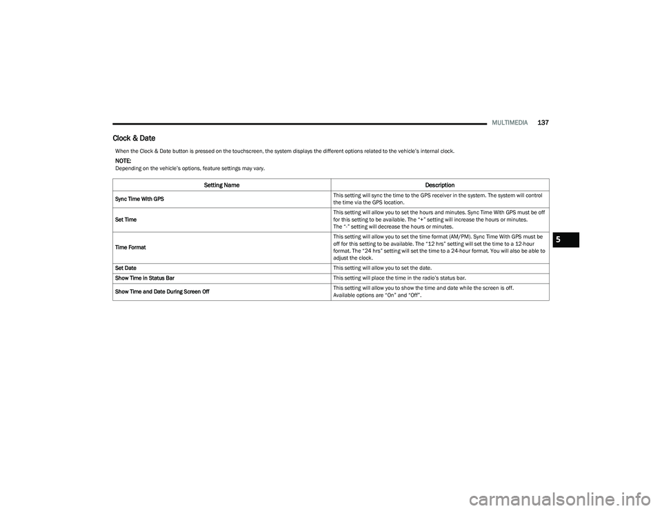
When the Clock & Date button is pressed on the touchscreen, the system displays the different options related to the vehicle’s internal clock.
NOTE:Depending on the vehicle’s options, feature settings may vary.
Setting Name Description
Sync Time With GPS This setting will sync the time to the GPS receiver in the system. The system will control
the time via the GPS location.
Set Time This setting will allow you to set the hours and minutes. Sync Time With GPS must be off
for this setting to be available. The “+” setting will increase the hours or minutes.
The “-” setting will decrease the hours or minutes.
Time Format This setting will allow you to set the time format (AM/PM). Sync Time With GPS must be
off for this setting to be available. The “12 hrs” setting will set the time to a 12-hour
format. The “24 hrs” setting will set the time to a 24-hour format. You will also be able to
adjust the clock.
Set Date This setting will allow you to set the date.
Show Time in Status Bar This setting will place the time in the radio’s status bar.
Show Time and Date During Screen Off This setting will allow you to show the time and date while the screen is off.
Available options are “On” and “Off”.
5
23_GG_OM_EN_USC_t.book Page 137
Page 209 of 288
IN CASE OF EMERGENCY207
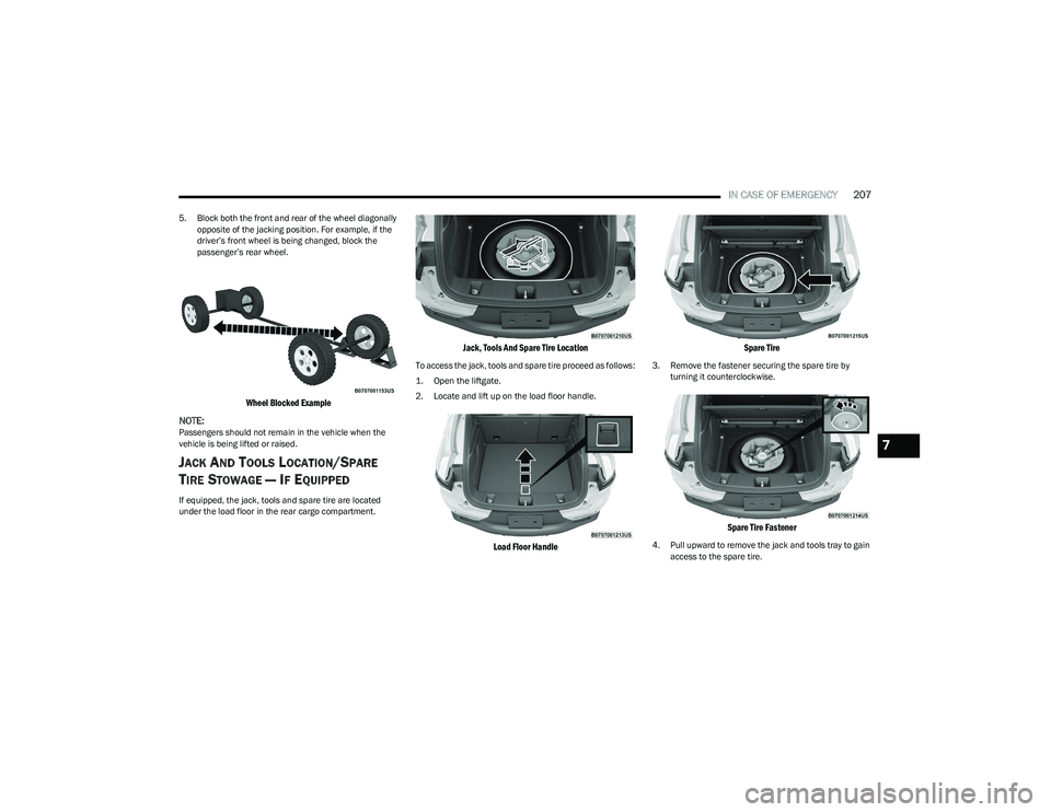
5. Block both the front and rear of the wheel diagonally
opposite of the jacking position. For example, if the
driver’s front wheel is being changed, block the
passenger’s rear wheel.
Wheel Blocked Example
NOTE:
Passengers should not remain in the vehicle when the
vehicle is being lifted or raised.
JACK AND TOOLS LOCATION/SPARE
T
IRE STOWAGE — IF EQUIPPED
If equipped, the jack, tools and spare tire are located
under the load floor in the rear cargo compartment.
Jack, Tools And Spare Tire Location
To access the jack, tools and spare tire proceed as follows:
1. Open the liftgate.
2. Locate and lift up on the load floor handle.
Load Floor Handle Spare Tire
3. Remove the fastener securing the spare tire by
turning it counterclockwise.
Spare Tire Fastener
4. Pull upward to remove the jack and tools tray to gain access to the spare tire.
7
23_GG_OM_EN_USC_t.book Page 207
Page 211 of 288
IN CASE OF EMERGENCY209
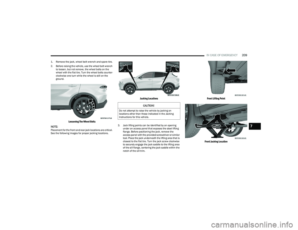
1. Remove the jack, wheel bolt wrench and spare tire.
2. Before raising the vehicle, use the wheel bolt wrench
to loosen, but not remove, the wheel bolts on the
wheel with the flat tire. Turn the wheel bolts counter -
clockwise one turn while the wheel is still on the
ground.
Loosening The Wheel Bolts
NOTE:
Placement for the front and rear jack locations are critical.
See the following images for proper jacking locations.
Jacking Locations
3. Jack lifting points can be identified by an opening under an access panel that exposes the steel lifting
flange. Before positioning the jack, remove the
access panel with the provided screwdriver or similar
tool. Place the jack underneath the lifting area that is
closest to the flat tire. Turn the jack screw clockwise
to securely engage the jack saddle to the lifting area
of the sill flange, centering the jack saddle within the
notch of the sill trim.
Front Lifting Point
Front Jacking Location
CAUTION!
Do not attempt to raise the vehicle by jacking on
locations other than those indicated in the Jacking
Instructions for this vehicle.
7
23_GG_OM_EN_USC_t.book Page 209
Page 212 of 288
210IN CASE OF EMERGENCY
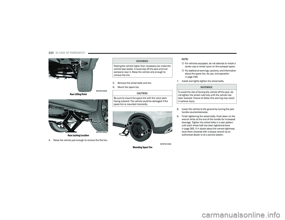
Rear Lifting Point
Rear Jacking Location
4. Raise the vehicle just enough to remove the flat tire. 5. Remove the wheel bolts and tire.
6. Mount the spare tire.
Mounting Spare Tire
NOTE:
For vehicles equipped, do not attempt to install a
center cap or wheel cover on the compact spare.
For additional warnings, cautions, and information
about the spare tire, its use, and operation
Úpage 246.
7. Install and lightly tighten the wheel bolts.
8. Lower the vehicle to the ground by turning the jack handle counterclockwise.
9. Finish tightening the wheel bolts. Push down on the wrench while at the end of the handle for increased
leverage. Tighten the wheel bolts in a star pattern
until each wheel bolt has been tightened twice
Úpage 265. If in doubt about the correct tightness,
have them checked with a torque wrench by an
authorized dealer or at a service station.
WARNING!
Raising the vehicle higher than necessary can make the
vehicle less stable. It could slip off the jack and hurt
someone near it. Raise the vehicle only enough to
remove the tire.
CAUTION!
Be sure to mount the spare tire with the valve stem
facing outward. The vehicle could be damaged if the
spare tire is mounted incorrectly.
WARNING!
To avoid the risk of forcing the vehicle off the jack, do
not tighten the wheel nuts fully until the vehicle has
been lowered. Failure to follow this warning may result
in serious injury.
23_GG_OM_EN_USC_t.book Page 210
Page 241 of 288
SERVICING AND MAINTENANCE239
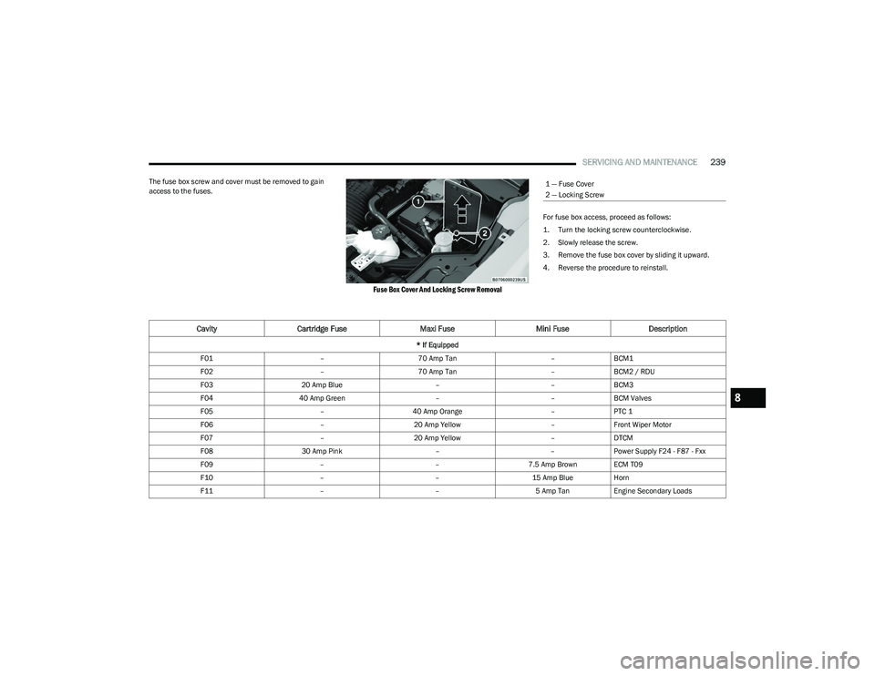
The fuse box screw and cover must be removed to gain
access to the fuses.
Fuse Box Cover And Locking Screw Removal
For fuse box access, proceed as follows:
1. Turn the locking screw counterclockwise.
2. Slowly release the screw.
3. Remove the fuse box cover by sliding it upward.
4. Reverse the procedure to reinstall.
1 — Fuse Cover
2 — Locking Screw
CavityCartridge Fuse Maxi FuseMini FuseDescription
* If Equipped
F01 –70 Amp Tan –BCM1
F02 –70 Amp Tan –BCM2 / RDU
F03 20 Amp Blue ––BCM3
F04 40 Amp Green ––BCM Valves
F05 –40 Amp Orange –PTC 1
F06 –20 Amp Yellow –Front Wiper Motor
F07 –20 Amp Yellow –DTCM
F08 30 Amp Pink ––Power Supply F24 - F87 - Fxx
F09 ––7.5 Amp Brown ECM T09
F10 ––15 Amp BlueHorn
F11 ––5 Amp TanEngine Secondary Loads
8
23_GG_OM_EN_USC_t.book Page 239